

Numatic TRO 650/200T Owner's Manual

Warning! Read instructions before using the machine
Owner Instructions
TRO 650 / 200T
RIDE-ON
SCRUBBER DRYER
www.numatic.co.uk
RIDE ON SCRUBBER DRYER
Index
After the removal of
all the packaging,
carefully open and
check the contents
●
Owner Manual
●
Battery Charging Lead
●
Key Switch
● 2 x
40 Amp Fuse
●
Maxi Fuse-puller
PLEASE
READ
BEFORE
COMMENCING
OPERATION
1
Operator control panel
2
Brush load adjuster knob
3
Brush deck release lever
4
Brush deck foot pedal
5
Clean water tank ll point
6
Side pod and skirt
7
Brush deck motors x 2
8
Side pod release lever
9
Floor-tool raise / lower lever
10
Seat adjustment lever
11
Separator release catches
12
40 Amp battery fuses x 2 (4 Battery Machine)
13
Gel batteries
14
Charger
15
Accelerator pedal
16
Clean-water tank emptying hose
17
Semi parabolic oor-tool
18
Vacuum hose
19
Waste-water emptying hose
20
Floor-tool vacuum hose
21
Air separator assembly
22
Pedestrian warning light
23
Water Pump
TRO 650 / 200T
Machine Overview ................................ Pages 2-3
Control Panel Overview ................................ Page 4
Machine Set up Guide ................................ Pages 5-10
Fitting the Floor tool ................................ Page 6
Fitting the Hose ................................ Page 7
Breakaway Floor tool Feature ......................... Page 7
Fitting the brush ................................ Page 8
Filling the Clean Water Tank ............................ Page 8
Maximum Speed Control ................................ Page 9
Emergency Stop Button and Horn ................ Page 9
Adjusting the Seat .............................. Page 9
Raise / Lower Brush Deck ............................. Page 10
Raise / Lower Floor-Tool ................................ Page 10
Setting the Cleaning Controls ......................... Page 11
Fill Level Indicator ................................ Page 11
Brush Pressure Adjustment ............................. Page 11
Hi / Lo Vacuum Setting ................................ Page 12
Machine Cleaning ................................ Page 13
Changing Floor tool Blades ............................. Page 14
Machine Charging ................................ Page 15
Battery Care ................................ Page 16
Free-Wheel Function ................................ Page 13
Changing Floor tool Blades ............................. Page 14
Machine Charging ................................ Page 15
Battery Care ................................ Page 16
Free-Wheel Function ................................ Page 17
O-aisle Cleaning Kit ................................ Page 18
Warning Lights ................................ Pages 19-20
Trouble Shooting ................................ Page 21
Specications ................................ Page 21
Rating Label / Personal Protective Equipment /
Recycling ................................ Page 22
Safety Precautions ................................ Pages 23-24
Recommended Spare Parts .......................... Page 25
Schematic Diagram ................................ Page 25
Battery Wiring ................................ Page 26
EU Declaration Document ............................. Page 27
Warranty ................................ Page 28
Company Address ................................ Page 32
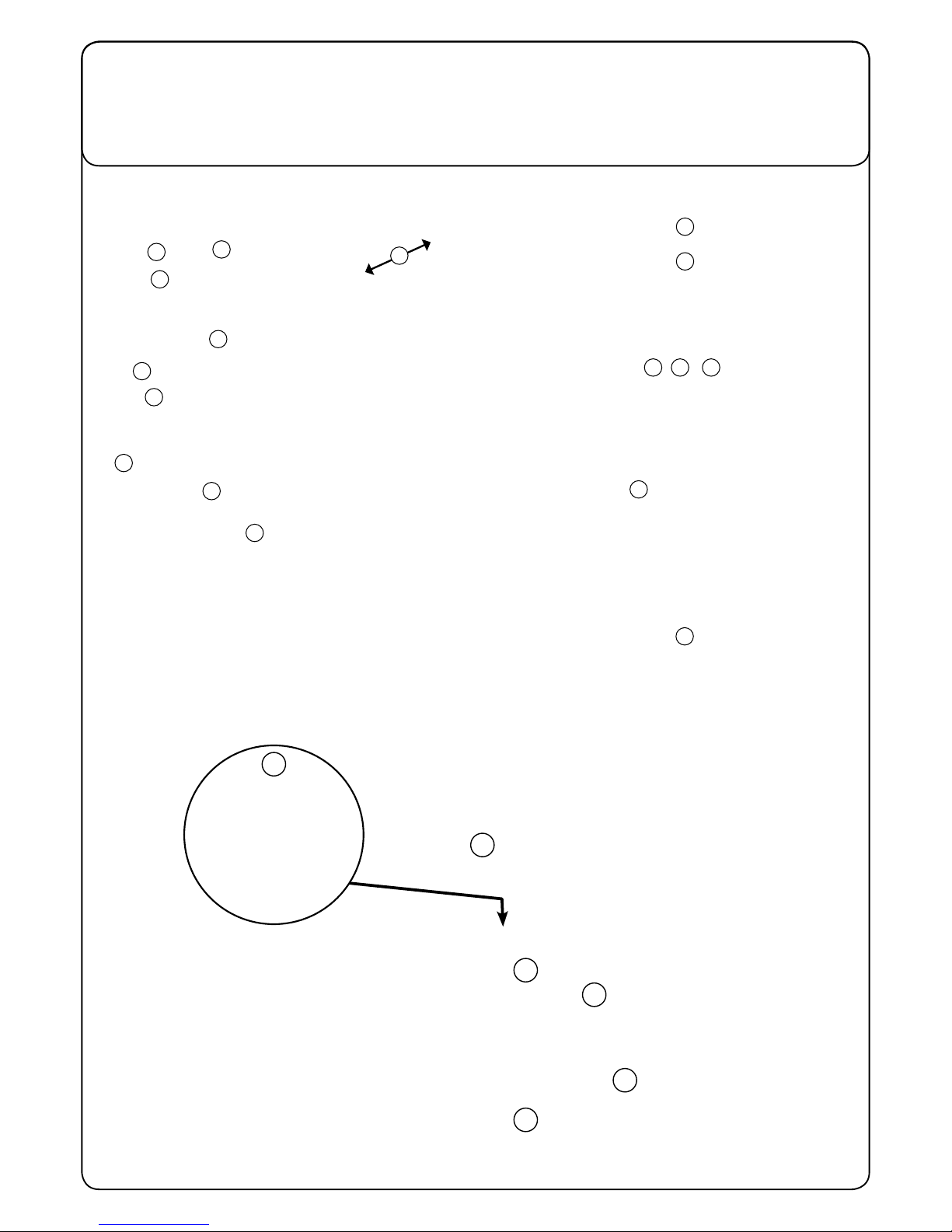
Machine Overview
13
14
6
12
22
21
18 19 20
16
17
11
10
9
2
3
4
5
6
7
8
15
23
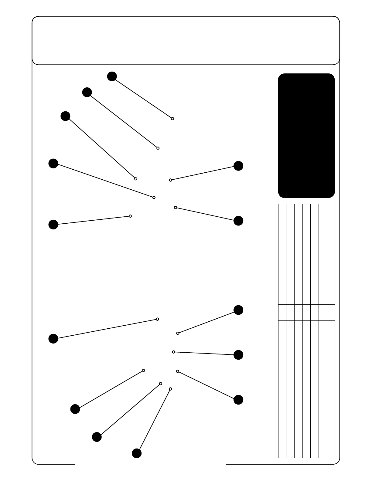
Control Panel Overview
RIDE ON SCRUBBER DRYER
TRO 650 / 200T
1
Battery Charge Level Meter
8
Emergency Stop
2
Brush Operation / Load Indicator
9
Horn Button
3
Water Flow Rate Indicator
10
Maximum speed control
4
Waste-water ‘Full’ Indicator
11
Traction Status Indicator
5
O Aisle Vacuum Button
12
Charging status light
6
Main control On / O key
13
Hours Meter
7
Forward / Reverse Switch
14
Vacuum Hi / Lo Button
In the event of a breakdown contact
your Numatic dealer or the
Numatic Technical
help line +44 (0)1460 269268
10
4
9
3
8
2
7
1115
6
12
13
14
Machine Set-up Guide
5
T 01460 68600
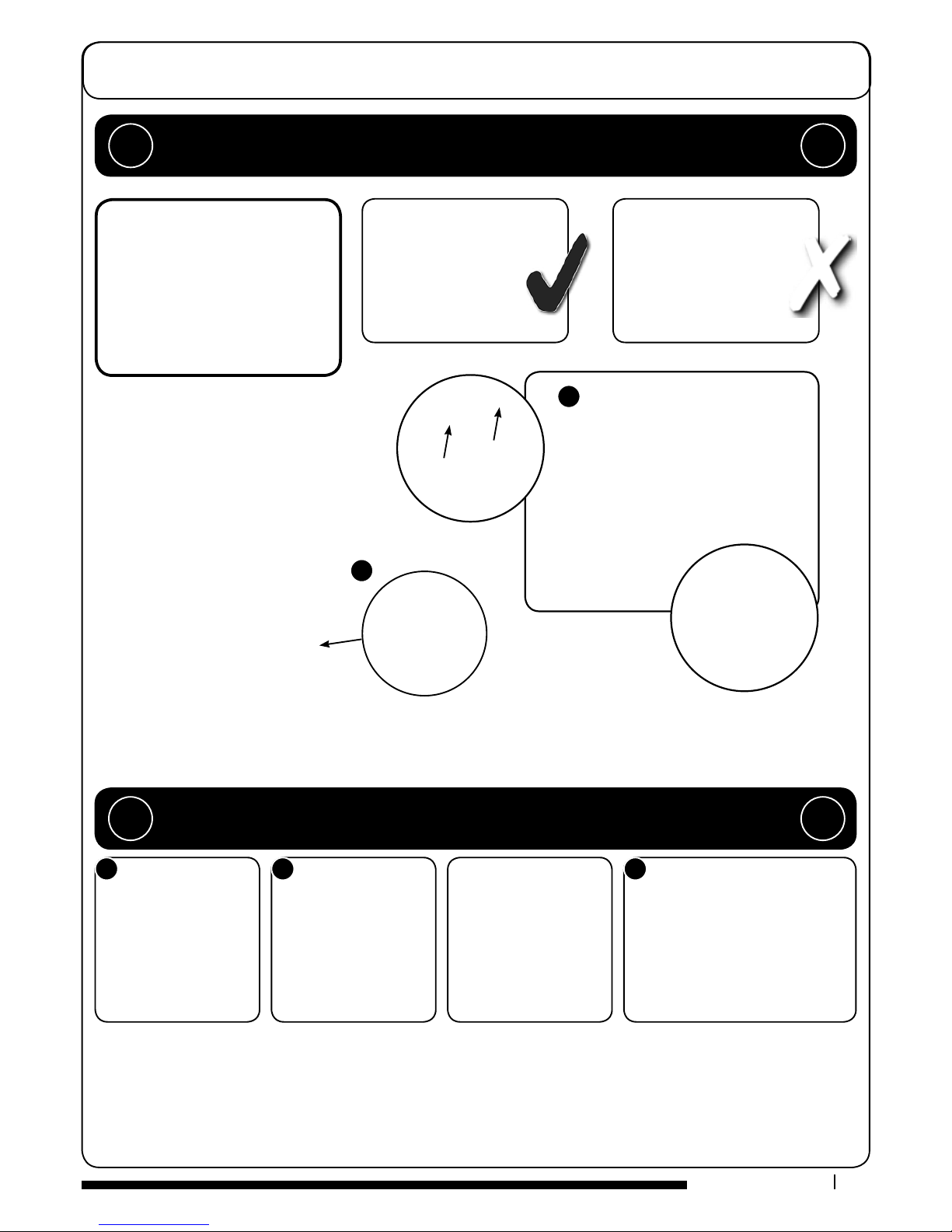
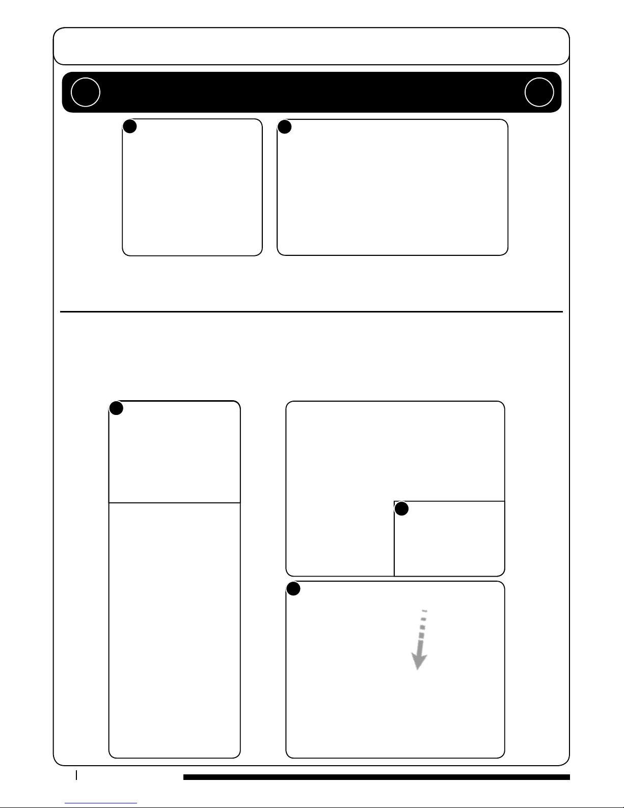
Lift top tank assembly to reveal battery compartment.
Always lift between points as illustrated to ensure personal safety.
Fit battery fuses (contained in start-up pack) into the battery fuse holders as illustrated (Fig.1).
Remove transit block from pallet (Fig.2).
1
2
5
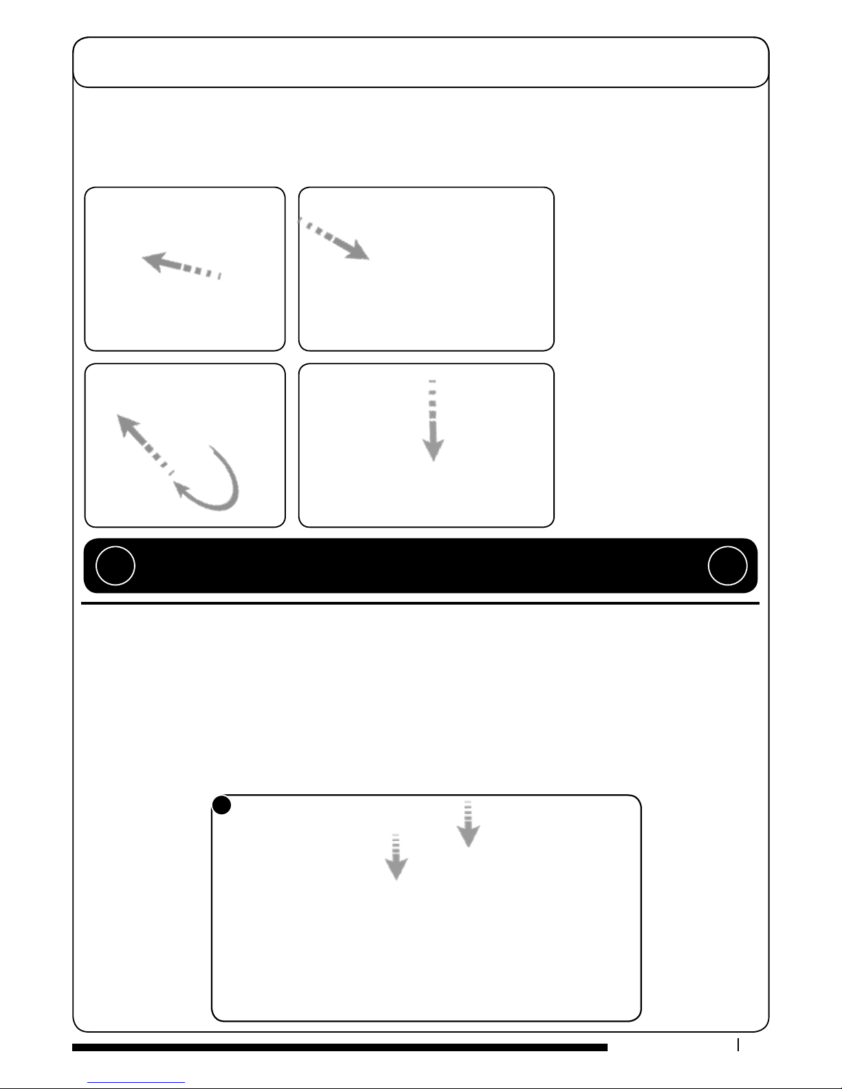
Insert key into main control (on / o) and turn quarter-turn clockwise to position (1) ‘On’ (Fig.3).
Ensure that the forward / reverse switch is set to forward (Fig.4).
Depress accelerator pedal with right foot and slowly drive machine o of the pallet using the ramp
provided (Fig.5).
Note: The seat is tted with a pressure sensor that disables the machine until
an operator is seated.
When the machine is removed and in a safe position, turn key back to the position (0) ‘OFF’ (Fig.6).
4
3
PLEASE READ BEFORE COMMENCING ANY OPERATION AFTER THE REMOVAL OF ALL
THE PACKAGING, CAREFULLY OPEN AND CHECK THE CONTENTS.
!!
NOTE: ENSURE THAT NO METAL OBJECTS COME INTO CONTACT WITH BATTERY
TERMINALS WHILE THE BATTERIES ARE EXPOSED.
WHEN INSERTING THE FIRST FUSE YOU MAY NOTICE A SPARK, THIS IS NORMAL.
!!
CONTENTS
1 x Owner Manual
2 x Battery Charging Lead
2 x Keys
3 x 40 Amp Fuse (1 spare)
2 x Side pod skirts
1 x Brake disengage key
1 x
Maxi Fuse-puller
Machine Set-up Guide
6
www.numatic.co.uk
Fitting the Floor-tool
To t the side pod skirts, rst remove the steel retaining strip already tted to the pod (Fig.7).
Align the steel retaining strip within the locating grooves of the rubber skirt and ret using existing screws (Fig.8)
Periodically the side skirts should be examined and checked for wear and damage. Replace as shown above.
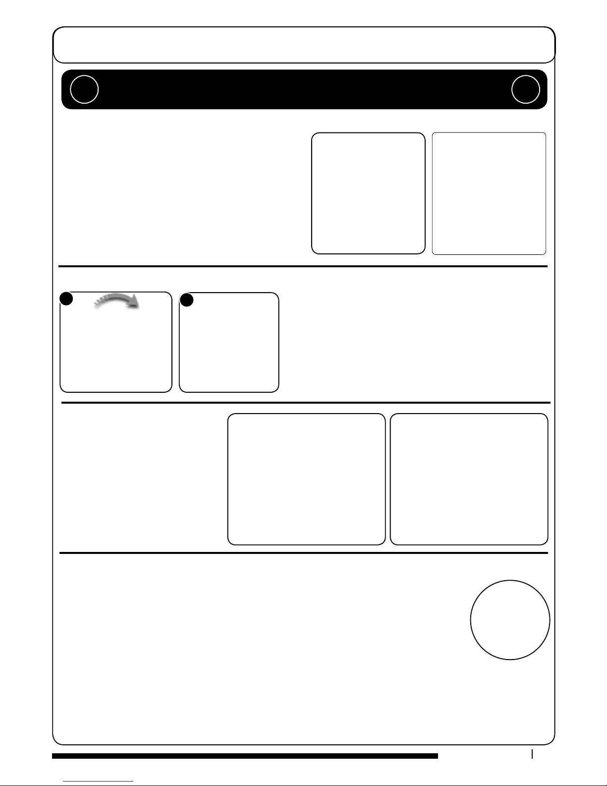
Lower the oor-tool arm by moving the release lever to the upper position (Fig.9).
Push oor-tool onto the holder and secure with the easy-t securing pin (Fig.10).
Push waste collection pipe onto the oor-tool; ensure a tight t (Fig.11).
Note: Raise oor-tool again before driving to the cleaning area.
7
8
9
10
11
ALWAYS ENSURE THAT THE MACHINE IS SWITCHED OFF
BEFORE MAKING ANY ADJUSTMENTS
!!
Machine Set-up Guide
7
T 01460 68600
Breakaway Floor-tool
The vacuum hose has a U-bend clip which creates a U-bend in the hose preventing water spillage when the vacuum is switched o. If
you need to remove the U-bend clip for any reason always ensure it is retted correctly before you resume operation.
Ret vacuum hose to the Floor-tool when nished.
Fitting the Hose Guide
The oor-tool design incorporates a safety knock-off feature.
Allowing it to safely disengage from its mounting should it become caught on an obstruction, during forward
machine movement.
To re-attach the oor-tool blade to its holder.
First loosen the retaining knobs on the oor-tool body and slide onto the holding bracket.
Tighten retaining knobs to nger tight. (See Fig.13).
13
Note:
DO NOT push the vacuum hose onto the Floor-tool with the Floor-tool in the raised position.
!!

Machine Set-up Guide
8
www.numatic.co.uk
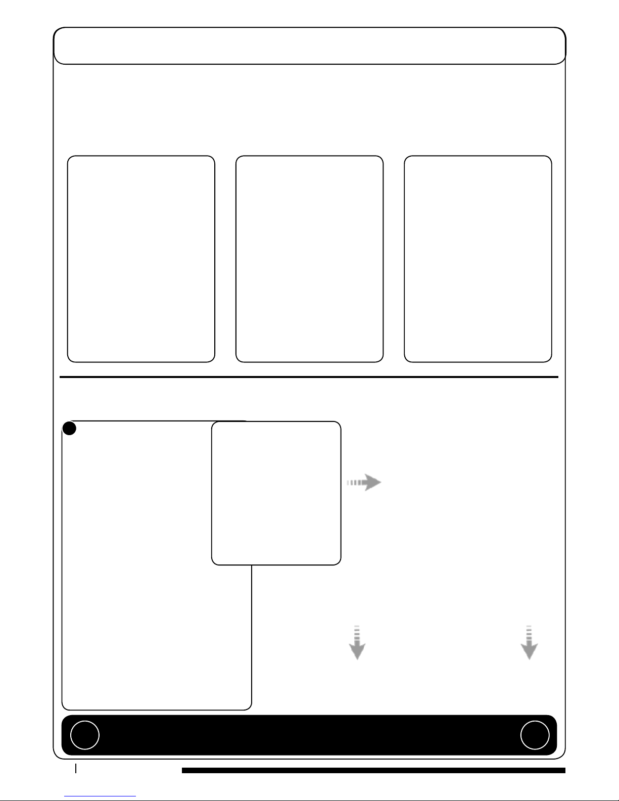
Featuring the OBS (Octagonal Brush System);
the brushes simply push-t up onto the chucks
making tting and removal a simple process.
Pull the side pod adjustment lever and set to the top position (Fig.14).
The side pod will now pull open (Fig.15).
Fit outer brush next on both sides (Fig.16).
Close side pod.
Safety gloves are recommended for the changing of used brushes.
Fitting the Brushes
14
15
16
The TRO 650 / 200T is equipped with a large capacity 120 litre clean-water tank allowing, for large areas to be covered
in a single ll. To ll the clean-water tank, lift the cover ap (Fig.17) to expose the ller cap.
Unscrew the ller cap (Fig.18) and ll the tank using a hose (Fig.19) or preferred method.
Filling the Clean-water Tank
171819
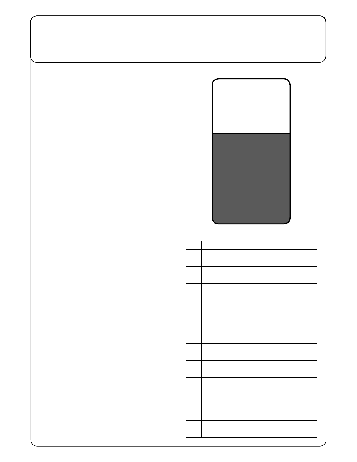
The water level in the clean-water
tank can be measured using the
scale on the rear of the machine
(Fig.20).
Always ensure that the waste-water
tank is empty before lifting.
20
Note: Great care must be taken to ensure that contaminants (leaves, hair, dirt, etc.) are not
allowed to enter the clean-water tank during the lling process. If using a bucket or similar,
ensure it is always clean and free from debris.
!!
Fill-level indicator
Machine Set-up Guide
9
T 01460 68600
The machine is now ready to be driven to the cleaning site.
Before performing the cleaning operation, place out appropriate warning signs and sweep or dust-mop the oor.
Use the maximum speed control knob and set desired
traction speed as required, depending on oor type and level
of soiling.
Middle speed is the optimum cleaning speed for most types
of oors.
Once the Max speed has been set using the control knob on
the control panel, ne adjustments can be made using the
variable control speed pedal located on the right side of the
footplate.
Maximum Speed Control
Emergency Stop Button and Horn
The TRO 650 / 200T is equipped with an electronic braking system.
Simply lift your foot from the accelerator and the machine will stop.
In an emergency, strike the emergency-stop isolator button
The machine will be disabled.
To reset, turn isolator button clockwise (see Fig.21).
After resetting the emergency stop button, to restart the
machine, turn the ignition key to (0) ‘OFF’ then to position
(1) ‘ON’ again.
The horn is located on the right-hand side of the operator control
panel (see Fig.22).
21
22
Sitting in the driving position, adjust
the seat forwards or backwards as
necessary by using the lever found on
the left-hand side (see Fig.23).
Note: The seat is tted with a
pressure sensor that disables the
machine until an operator is seated.
Adjusting the Seat
IMPORTANT
Do not operate machine unless the Operator Manual has been read and fully understood.
!!
Machine Set-up Guide
10
www.numatic.co.uk
Lowering the Floor-tool
27
After preparing the oor (see previous section), we are now ready to set the controls to suit the cleaning conditions.
Before any settings can be applied, ensure the brush deck is lowered.
While depressing left-hand foot pedal (see Fig.24), press down the release lever (see Fig.25) and gently release the foot
pedal to lower the brush deck (see Fig.26).
Lowering the Brush Deck
Note:
DO NOT push the vacuum hose onto the Floor-tool with the Floor-tool in the raised position.
!!
 Loading...