

Numatic TGB1620T, TGB 1620 Owner's Manual

Warning! Read instructions before using the machine
Owner Instructions
TGB 1620
TGB1620T
BATTERY SCRUBBER DRYER
www.numatic.co.uk

Machine Overview ................................ Pages 2-3
Control Panel Overview ................................ Page 4
Machine Set up Guide ................................ Page 5
Fitting the Brush / Pad ................................ Page 6
Fitting the Floor Tool ................................ Page 6
Fitting the Hose Guide ................................ Page 7
Filling the Clean Water Tank .......................... Page 7
Fill Level Indicator .............................. Page 8
Lowering the Floor Tool ................................ Page 9
Raise / Lower Brush Deck ............................... Page 9
Setting the Cleaning Controls .................... Page 9
Brush Pressure .............................. Page 10
Breakaway Floor Tool ................................ Page 10
Machine in Use ................................ Page 10
Machine Cleaning ................................ Page 11
Waste Water Tank Full ................................ Page 11
Changing Floor tool Blades ............................. Page 12
Machine Charging ................................ Page 13
Battery Care ................................ Page 14
Charging Lights Sequence .............................. Page 14
TGB6055T Operation ................................ Page 15 - 16
Specications ................................ Page 17
Trouble Shooting ................................ Page 17
Rating Label / Personal Protective
Equipment /Recycling ................................ Page 18
Safety Precautions ................................ Page 19-20
Recommended Spare Parts .......................... Page 21
Schematic Diagram ................................ Page 21
EU Declaration Document ............................. Page 22
Warranty ................................ Page 22
Company Address ................................ Page 24
TGB 1620
BATTERY SCRUBBER DRYER
Index
After the removal of all the packaging,
carefully open and check the contents
●
Owner Manual ● 2 x Ignition Keys
●
Battery Charging Lead ● 2 x 40 Amp Fuse
(Battery) ● 1 x 30 Amp Fuse (Brush)
●
1 x 20 Amp Fuse (Vac)
●
1 x 2.5 Amp Fuse ● Maxi Fuse-puller
For Charger-less Model, all the above plus:
●
1 x Charger Connector ● 2 x Charger
Connector Terminals ● 4 x Battery Terminal
Connectors ● 1 x Fuse Holder
PLEASE READ
BEFORE COMMENCING
OPERATION
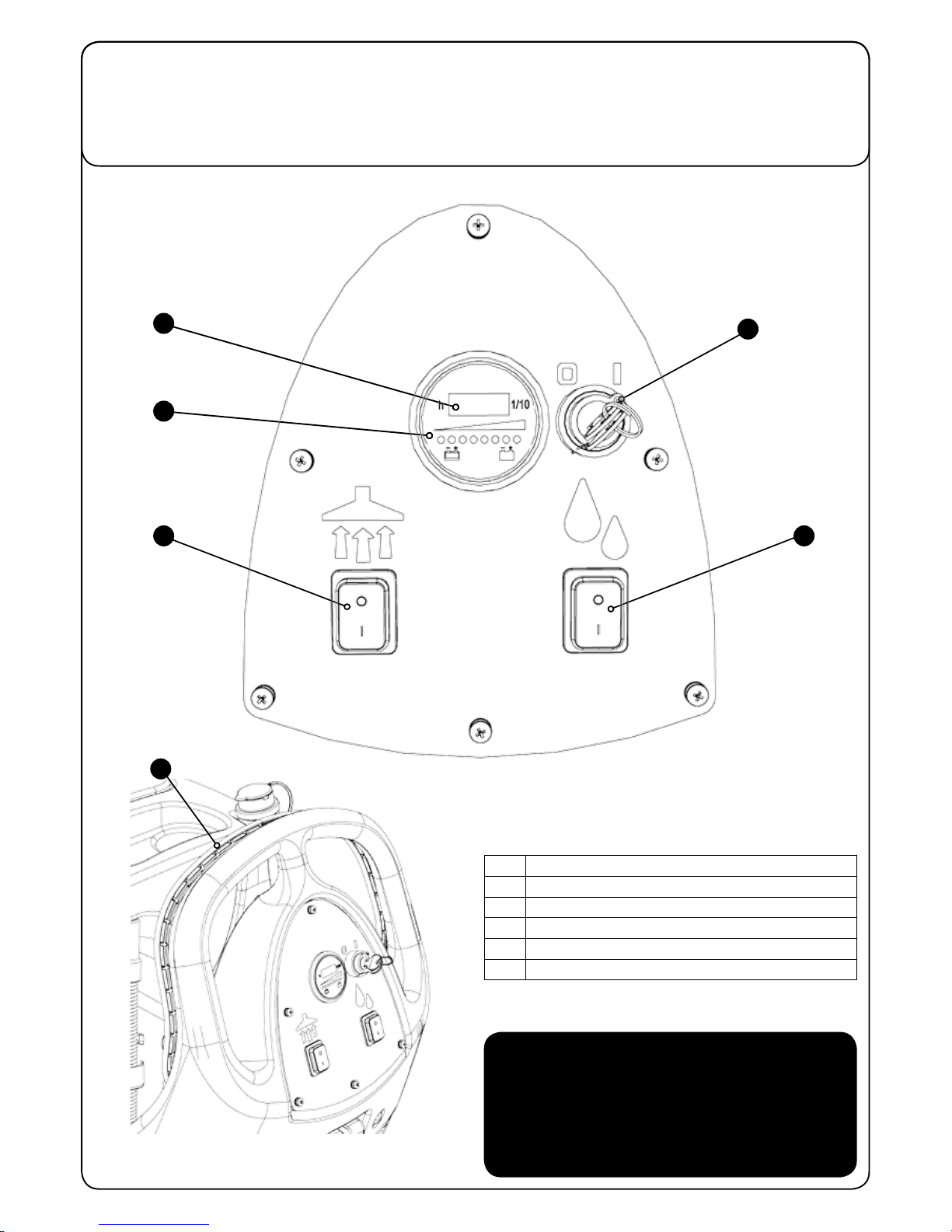
1
Operator control panel
2
Charging Socket / Point
3
Clean Water Fill Point
4
Floor Tool Raise / Lower Lever
5
Clean Water Tank Emptying Hose & Fill Level
6
Vacuum Hose
7
Charging Lights
8
Brush Deck Lifting Pedal
9
Extra Brush Load Pedal
10
Semi Parabolic Floor Tool
11
Brush On/O / Control Handle
12
Safety Fuse 2.5 Amp
13
Batteries
14
40 Amp Battery Fuse (50 Amp in Traction Machine)
15
Brush Motor Fuse 30 Amp
16
Vac Motor Fuse 20 Amp
17
Brush Deck
18
Clean Water Filter
19
Water Flow Tap
20
Waste Water Emptying Hose
21
Separator
22
Top Tank (Waste Water)
23
Bottom Tank (Clean Water)
24
Detent Pin
25
Key Ignition. On/O

6
4
2
1
3
14
15
16
17
9
8
7
11
Machine Overview
5
10
13
12
18
20
192122
23
24
25
For Traction Drive Twintec see pages 15 & 16
TGB 1620
BATTERY SCRUBBER DRYER
1
Key Ignition Switch
2
Hours Meter
3
Battery Charge Level Indicator
4
Vacuum Pick Up On / O
5
Water Flow On / O
6
Brush On / O / Control Handle
Control Panel Overview
In the event of a breakdown contact
your Numatic dealer or the
Numatic Technical
help line +44 (0)1460 269268
2
1
5
3
6
4
5
T 01460 68600
“
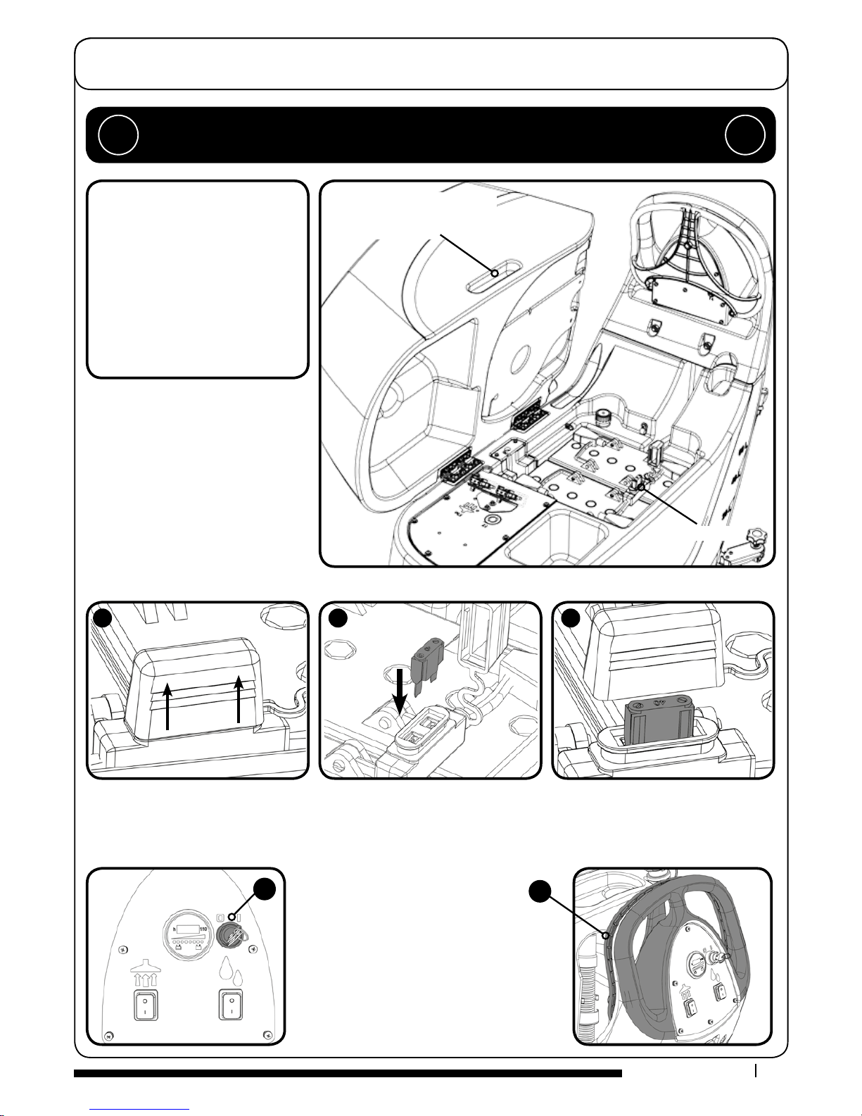
Ensure that no metal objects come into contact with
battery terminals while the batteries are exposed.
When inserting the rst fuse you may notice
a spark, this is normal.
”
Insert the Ignition key and
switch the machine on.
(Fig. A)
Use handle grip when
raising or lowering the
top waste-tank.
Fuse Location
Machine Set-up Guide
TGB
1620 CONTENTS
●
2 x Ignition Keys ● 2 x 40 Amp Fuse
(Battery) ● 1 x 30 Amp Fuse (Brush)
●
1 x 20 Amp Fuse (Vac)
●
1 x 2.5 Amp Fuse ● Maxi Fuse-puller
For Charger-less Model,
all the above plus:
●
1 x Charger Connector ● 2 x Charger
Connector Terminals
●
4 x Battery Terminal Connector
covers ● 1 x Fuse Holder
Lift top tank assembly to reveal battery
compartment, ensuring you use the handle
grip provided.
Fit battery fuse (contained in start-up pack)
into the battery fuse holder as illustrated.
(Fig. 1, 2, 3.)
Insert Key into ignition located on the
control panel (See below (Fig. A)
NOTE: Wear suitable gloves when
inserting fuses.
Using the control handle with both hands,
slowly push the machine o the pallet.
When the machine is removed and in a safe position,
release the control handle.
Note: Do not pull the RED trigger handle while in
transport mode (Fig. B)
During vehicular transportation ensure the product
is secured to avoid unnecessary movement.
PLEASE READ BEFORE COMMENCING ANY OPERATION AFTER THE REMOVAL OF ALL
THE PACKAGING, CAREFULLY OPEN AND CHECK THE CONTENTS.
!!
B
A
123
6
T 01460 68600
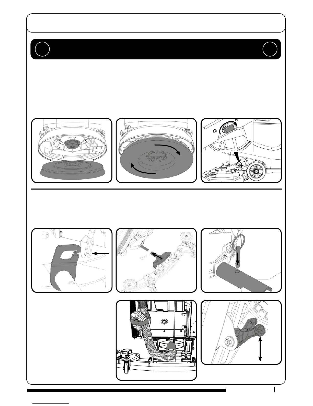
Fit the oor tool and retain using the
detent pin.
Push waste collection pipe onto the
oor tool; ensure a tight t.
Raise the oor tool for transit or
lower for cleaning operation using
the lifting handle tted to the back
of the machine.
For tting the oor tool blades
(See Page 12).
Machine Set-up Guide
ALWAYS ENSURE THAT THE MACHINE IS SWITCHED OFF
BEFORE MAKING ANY ADJUSTMENTS
!!
550mm Brush or a 500mm Pad on the TGB 1620.
Featuring the Nulock brush system.
The brush is simply pushed and twisted to lock, making
tting and removal a simple process.
Slide the brush / pad under the brush deck.
Fit the brush / pad onto the Nulock drive chuck, twist to lock the brush / pad in place.
Safety gloves are recommended for the changing of used brushes.
Turn on the clean water tap.
Fitting the Brush / Pad / Turn on water
Fitting the Floor Tool
The oor tool has been designed for quick tting, allowing easy squeegee blade replacement and a safety knock-o feature if the
oor tool gets snagged, whilst in transit.
NOTE: It is easier to t the oor tool if the weight of the machine is resting on the brush. Ensure the brush is tted rst.
7
T 01460 68600
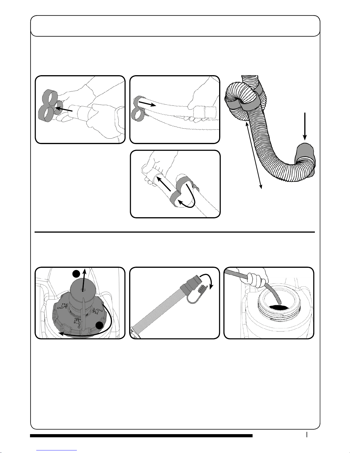
The vacuum hose has a U-bend clip which creates a U-bend in the hose preventing water spillage when the vacuum is switched
o. If you need to remove the U-bend clip for any reason always ensure it is retted correctly before you resume operation.
Fitting the Hose Guide
NOTE: DO NOT push the vacuum hose
onto the oor tool with the oor tool in
the raised position.
Machine Set-up Guide
Ret vacuum hose to the
Floor tool when nished.
250mm - 300mm
NOTE: Great care must be taken to ensure that contaminants (leaves, hair, dirt, etc.) are not allowed to enter the clean water
tank during the lling process. If using a bucket or similar, ensure it is always clean and free from debris.
F
illing the Clean Water Tank
The TGB 1620 is equipped with a large capacity clean water tank allowing for large areas to be covered in a single fill.
10
To ll the clean water tank, extend the hose located to the rear of the machine in the centre of the removable ller cap (1). Pull out
hose. Open the stopper and place hose under water tap, or use a hose to commence lling. The tank can also be lled by unscrewing
the ller cap and using a bucket or similar container (2).
1
2
8
T 01460 68600
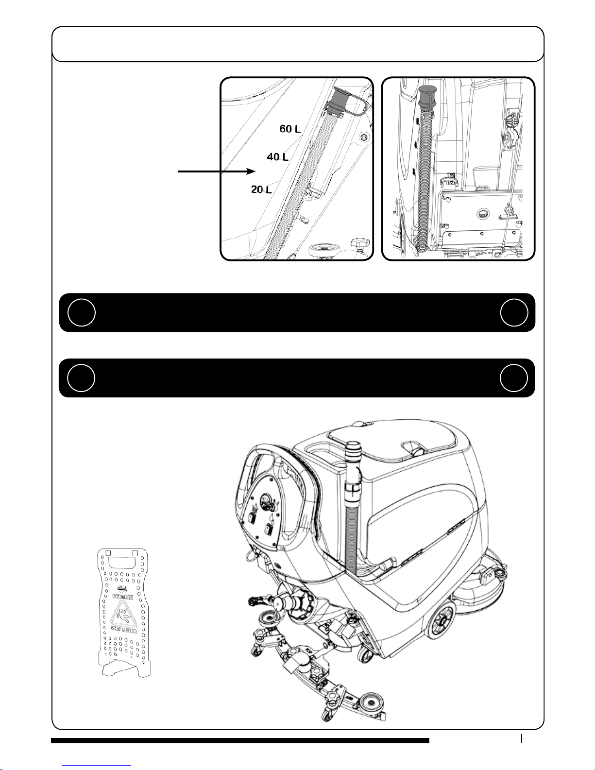
The water level in the clean-water tank
can be measured using the scale on the
left rear side of the machine. The clean
water bottom tank holds 60 litres.
NOTE: always ensure that the waste
water tank is empty before lifting.
Machine Set-up Guide
Fill Level Indicator
WHEN HANDLING AND MIXING CHEMICALS
Always ensure that chemical manufacturer’s safety guidelines are followed.
Only use chemicals recommended for use in auto scrubber-dryers.
!!
The machine is now ready to be moved to
the cleaning site.
Before performing the cleaning operation,
place out appropriate warning signs and
sweep or dust-mop the oor.
IMPORTANT
Do not operate machine unless the Operator Manual has been read and fully understood.
!!
 Loading...