

Page 1
SUMMARY
OPTIONS SELECTION
u
At the back of the thermostat, there are two selection switches to set
your preference.
Temperature in °C or °F.
1
Time in 12 or 24 hours.
2
u
TO SET TIME AND DAY
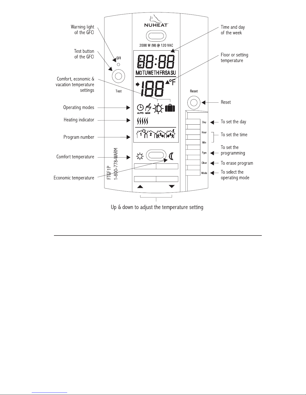
Press on DAY, HOUR and MIN buttons to adjust time and day.
u
TO RECORD THE (COMFORT) SETPOINT TEMPERATURE
Select chosen setpoint temperature by using or button. Press on
button (2 to 3 seconds) until icon appears on display.
u
TO RECORD THE (ECONOMIC) SETPOINT TEMPERATURE
MODEL FTGF1P (120 VAC)
Select chosen setpoint temperature by using or button.
Press on button (2 to 3 seconds) until icon appears on display .
u
CHECKING GROUND FAULT CIRCUIT INTERRUPTER (GFCI)
Adjust the setpoint temperature until heating indicator ( ) appears on
display. Press on TEST button. The test is conclusive if the warning light
(GFI) on thermostat is ON and power to the load is cut-off ( remain
on display though). If these events do not occur, check the installation.
Press on RESET button to reset the GFCI.
u
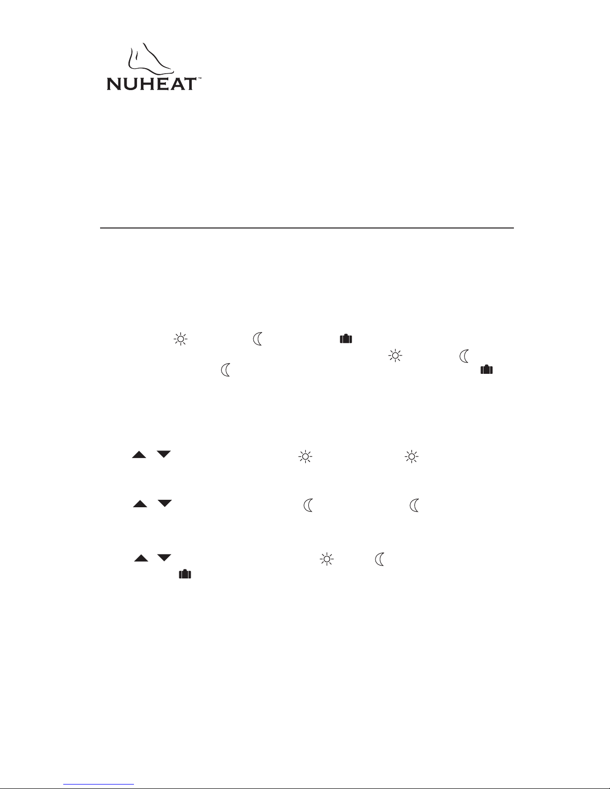
OPERATING MODES
To select an operating mode, use MODE button.
AUTO: Runs the program. or shows temperature setting
and can temporarily override your programming up to the
next program.
MAN: Maintains the selected temperature. or changes
the temperature setting.
720-111009 1/8
Page 2
INSTALLA
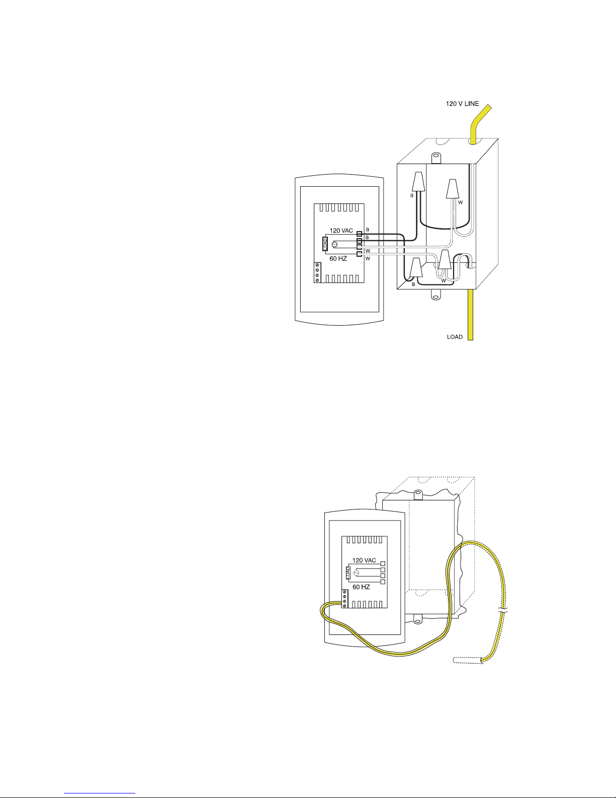
This thermostat is designed to control electric floor-warming systems. The
resistive load must not exceed 2000 watts (NI) @ 120 VAC (16.7 A). The
thermostat is equipped with a ground fault circuit interrupter (GFCI) and therefore
the isolation of the line and load are required for operation. Do not cap all the
white wires together. During a ground fault, only the current in the black wire
(line) of the load will be cut-off. Connect thermostat as shown on diagram.
A certified electrician must install the thermostat.
TION
PARTS INCLUDED
- One (1) FTGF1P (120 VAC) thermostat
- Two (2) 6-32 screws
- Four (4) solderless connectors (for copper wire)
- One (1) Temperature sensor with a 15 foot extension
TURN OFF POWER OF THE HEATING SYSTEM A
PANEL TO AVOID ELECTRICAL SHOCK. Keep air vents of the thermostat
clean and free from obstructions.
720-111009 2/8
T THE MAIN POWER
Page 3
1) Connecting wires and mounting thermostat
Connect the rear thermostat wires
to the power supply and to the
load using solderless connectors
for copper wires. See schematic
diagram.
Push the excess wire back into
the electrical box to prevent interference with the thermostat.
Secure the thermostat using two
(2) 6-32 screws. Once the
thermostat is properly installed,
return power to heating system.
Note 1: All cables and connections must conform to the local
electrical code.
WARNING: Special CO/ALR solderless connectors must be used when
connecting with aluminum conductors.
2) Connecting temperature sensor wire
Connect the temperature sensor
wire to the two lower screws of the
terminal block at the back of the
thermostat (no polarity needs to
be respected). The wire must pass
outside the electrical box and
follow the wall down to the floor.
The sensing probe should be
placed in a representative heat
area for maximum system
perfomance.
The sensing probe should be
centered between the wires in
the mat. The temperature sensor wire cannot cross any
heater wires and the sensing
probe must not be directly ON
or adjacent to a heating wire.
720-111009 3/8
Power-up
Page 4
To power up thermostat:
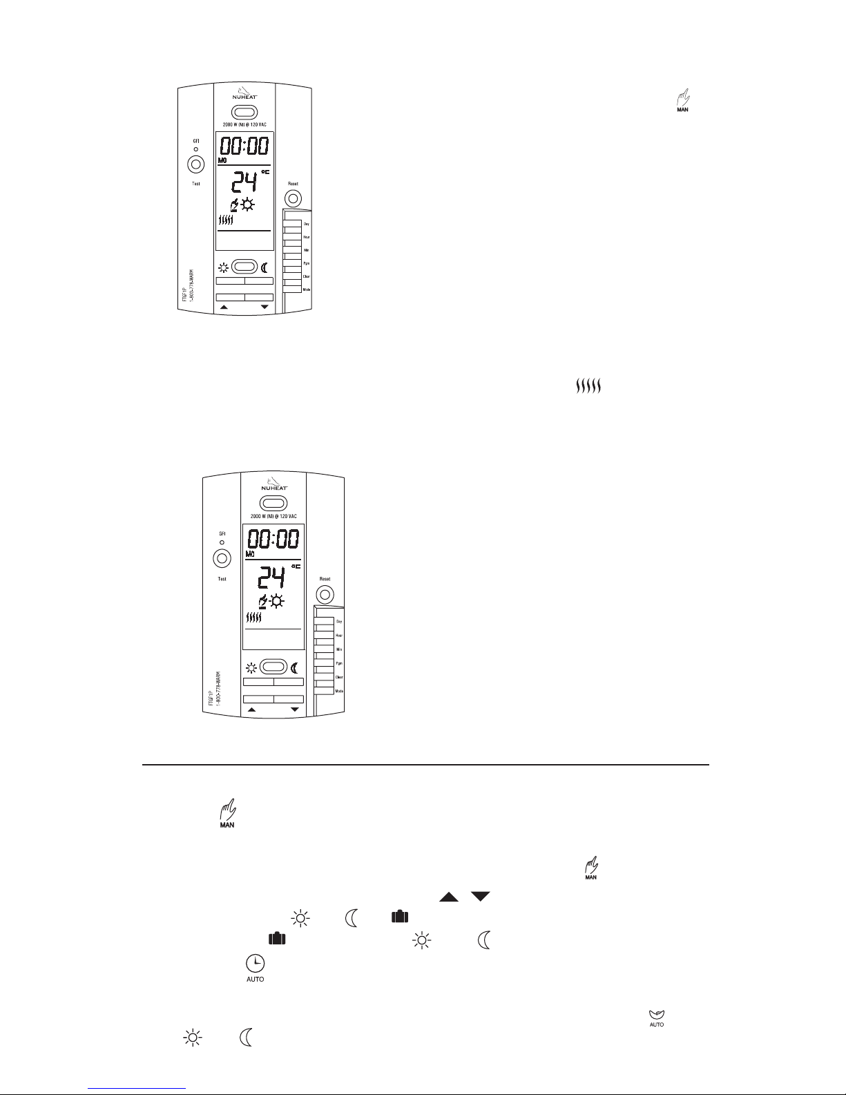
When power is applied for the first time, the
display must show the time 00:00, the floor
temperature and the manual mode icon ( ).
Other information might show up on the display if
installation is defective or does not comply with
the instructions. The warning light (GFI) must be
off.
L0 will appear if temperature is below 0 °C
(30 °F), temperature probe defective (open) or not
connected. Also, the heating indicator will be
present on display and the relay will be closed
(current going in the load).
HI will appear if temperature higher than 60 °C
(140 °F) or temperature probe shorted.
Checking ground fault circuit interrupter (GFCI)
Adjust the setpoint temperature until heating indicator ( ) appears on
display. Press on TEST button. The test is conclusive if the warning light (GFI) on
the thermostat is ON and power to the load is cut-off. If these events do not occur,
check the installation. Press on RESET button to reset the GFCI.
If the GFCI test fails:
Check the load wires. The thermostat
must be in heating mode to carry out the
test (heating indicator ON).
The GFCI test should be carried out
monthly. If the test fails, cut off the electric
power to the heating system and call
customer service or return the thermostat
to your supplier for verification. If the
warning light comes on during normal
operation, cut off power to the heating
system and have an electrician verify the
installation.
OPERA
The FTGF1P has two (2) operating modes.
M
ANUAL ()
This mode allows you to maintain a constant temperature on the floor.
o activate this mode, press on Mode button to display the icon.
1- T
2- Set the desired temperature using the buttons or select the
pre-programmed or or settings.
(To select the setting, press on and simultaneously
TING MODES
.)
720-111009 4/8
AUTO
This mode executes your own programming.
To activate this mode, press on Mode button to display the icon.
The or icon indicates which temperature setting is used. Also, the icon
of the program number will be shown.
MATIC ()
Page 5
Memory back-up
In the event of a power failure, an internal circuit will maintain the programming
and the time. Only the time will have to be set if a power failure is more than
6 hours.
PROGRAMMING
Programming the time and day
1-Set the time using the Hour and Min buttons.
2-Set the day using the Day button.
Programming the Comfort, Economic and Vacation settings
The Comfort , Economic and Vacation settings respectively represent
the temperatures that you wish to have during the day , at night or while
you are away at work , or while you are away for an extended period .
To program your settings
a) To program the Comfort temperature, select the desired degree using the
buttons and press the button until the icon is displayed
(approx. 3 seconds).
b) To program the Economic temperature, select the desired degree using the
buttons and press the button until the icon is displayed
(approx. 3 seconds).
c) To program the Vacation temperature, select the desired degree using the
buttons and press on the and buttons simultaneously
until the icon is displayed (app. 3 seconds).
d) Press the Mode button to exit this function and return to the normal
operating mode.
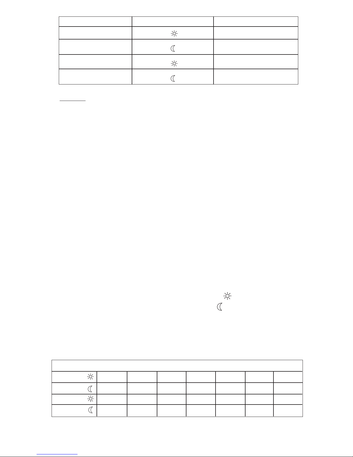
Schedule programming
The FTGF1P allows 4 setting changes for each day of the week. There are no
presset programs.The programs are tailored to perfectly adapt to your life style.
The principle is very simple. For each day, enter the time at which you wake up
(P1), the time you leave for work (P2), the time you arrive back home (P3) and
the time you go to bed (P4).
720-111009 5/8
Page 6
Program
Mode
Time
1
2
3
4
Wake-up time
Leaving time
Return time
Bed time
NOTE : For temperature increases (Prog. 1 and 3), allow at least
1 hour. If you have lowered the temperature during the night
and you wake up at 7:00 AM, change the setting to 6:00 AM.
a) To Program your Schedule
1- Press on PGM button to access the programming mode.
2- Press on Day button to select the day to be programmed. You can select
all days of the week by pressing on Day button for 3 seconds.
3- Press on PGM button to select program 1, 2, 3 or 4.
4- Press on Hour and Min buttons to program the time.
5- When you have completed your programming, press on Mode button
to exit this function.
b) To Erase a Program :
Select the program using PGM and Day buttons, and press on Clear
button. The time field displays --:-- when the program is inactive.
c) Example 1 : Comfort period from 7:00 AM to 10:30 PM
Economy period from 10:30 PM to 7:00 AM
Identical schedule for all days of the week.
1- Press on PGM button to access the programming mode.
2- Press on Day button 3 seconds to select every day of the week.
3- Press on Hour button to enter 7:00 AM, Prog. 1 ( ).
4- Press on PGM button again to select Prog. 2 ( ), and press on
Hour and Min buttons to enter 10:30 PM.
5- Press on Mode button to exit this function.
d) Example 2 : Comfort period: Monday to Friday from 6:15 AM to
8:15 AM and from 5:00 PM to 10:00 PM.
Schedule/Day
PROG. 1
MON.
6:15
AM
TUES.
6:15
AM
WED.
6:15
AM
THU.
6:15
AM
FRI.
6:15
AM
SAT.
7:30
AM
SUN.
7:30
AM
720-111009 6/8
PROG. 2
PROG. 3
PROG. 4
8:15 AM
5 PM
10 PM
NOTE : It is faster to program the same schedule for every day and then
modify the exception days.
8:15 AM
5 PM
10 PM
8:15 AM
5 PM
10 PM
8:15 AM
5 PM
10 PM
8:15 AM
5 PM
10 PM
11
---
---
PM
11
---
---
PM
Page 7
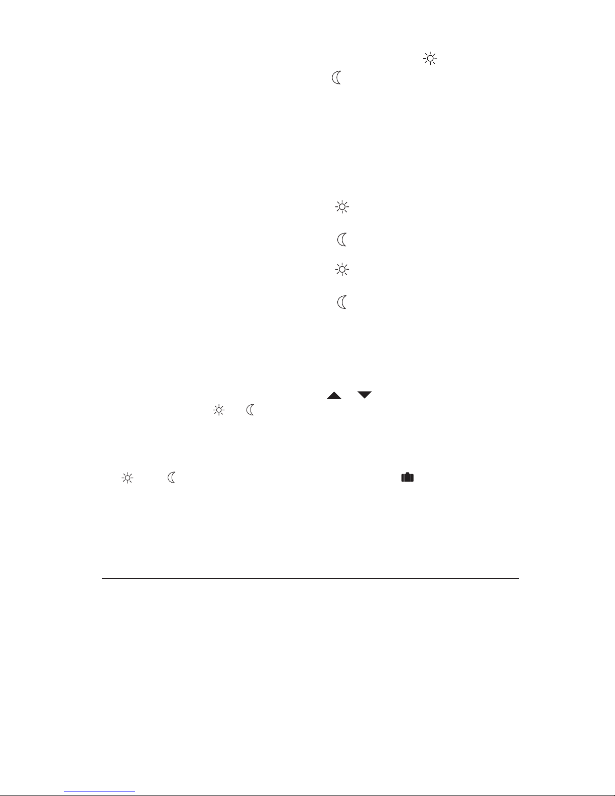
1- Press on PGM button to access the programming mode.
2- Press on Day button 3 seconds to select every day of the week.
3- Press on Hour and Min buttons to enter 6:15 AM Prog. 1, ( ).
4- Press on PGM button to select Prog. 2 ( ) and Hour and Min buttons to
enter 8:15 AM.
5- Repeat step 4 to enter Prog. 3 (5:00 PM) and Prog. 4 (10:00 PM).
NOTE : When making modifications, make sure you are in the right
program.
To modify the Saturday and Sunday schedules:
6- Press on Day button until SA or SU is displayed.
7- Press on PGM button to select Prog. 1 ( ) and Hour and Min
buttons to enter 7:30 AM.
8- Press on PGM button to select Prog. 2 ( ) and then Clear button to
erase it.
9- Press on PGM button to select Prog. 3 ( ) and then Clear button to
erase it.
10- Press on PGM button to select Prog. 4 ( ) and then Hour and Min
buttons to enter 11:00 PM.
11- Press on Mode button to exit this function.
Temporary or permanent temperature bypass
This operation allows you to temporarily modify the floor temperature while you
are in the Automatic mode. Simply press on or buttons to select the desired
temperature, or the or button to select the Comfort or Econo settings you
have programmed. This temperature will be maintained until the beginning of the
next programmed schedule.
You can also switch to the Vacation setting for a prolonged absence by pressing
on and at the same time. The display will show icon. In that case,
the temperature bypass is permanent. To return to the normal operating mode,
press on Mode button.
If you wish to immediately return to the programmed settings, press on Mode
button twice.
CHARACTERISTICS
• Model: FTGF1P (120 VAC)
• Supply: 120 VAC, 50/60 Hz
• Load: 16.7 A maximum (Resistive only)
• Power: 2000 watts (NI) @ 120 VAC
• Ground fault circuit interrupter (GFCI): Class A (5 mA TRIP LEVEL)
• Approvals: CSA / C, US
• Display range: 0 to 60 °C (32 to 140 °F)
• Setting range: 5 to 40 °C (40 to 104 °F)
• Comfort default setting: 28 °C (82 °F)
• Econo default setting: 18 °C (64 °F)
• Storage: -20 to 50 °C (-4 to 120 °F)
720-111009 7/8
Page 8

WARRANTY
NUHEAT INDUSTRIES LIMITED. ONE (1) YEAR LIMITED WARRANTY
This product is warranted against material defects and workmanship in normal
use for a period of one year, from the date of the original purchase from author
ized dealers. During this period, NUHEAT will repair or replace the product with a
new or of equivalent quality at NUHEAT’S option, without charge, any product
proven defective in normal use.
Warranty does not cover transportation costs. Nor does it cover a product subjected to misuse or accidental damage. This warranty does not cover the cost of
installation, removal or reinstallation.
This limited warranty is in lieu of all other warranties, obligations or liabilities
expressed or implied by the company. In no event shall NUHEAT be liable for
consequential or incidental damages resulting from installation of this product.
Some states or provinces do not allow limitations on how long an implied warranty
lasts, or the exclusion or limitation of incidental or consequential damages, so the
above exclusions or limitations may not apply to you. This warranty gives you
specific legal rights and you may also have other rights which vary from state to
state.
-
The defective product and the original sale receipt must be returned to the
original dealer or shipped pre-paid, insured and addressed to:
NUHEAT INDUSTRIES LIMITED.
CANADA USA
1689 Cliveden Ave.
Delta, B.C.
V3M 6V5
Web site: www.nuheat.com
If you have any questions concerning the installation or programming of this
product, please call our technical assistance at
Monday to Friday between 6:00 AM and 5:00 PM Pacific time.
880 Grant Street
Blaine, WA 98230
1-800-778-WARM (9276),
720-111009 8/8
 Loading...