

Page 1
OPERATION MANUAL
SigMod
Custom Signal Architecture Made Easy
© 2019 NUGEN Audio
1
www.nugenaudio.com
Page 2

SigMod Operation Manual
Contents
Introduction
General Operation
Interactive Signal-ow
Settings
Modules
Utility Controls
Reporting a Problem
3
4
5
6
7
12
14
Version History
15
© 2019 NUGEN Audio
2
www.nugenaudio.com
Page 3

SigMod Operation Manual
Introduction
NUGEN Audio SigMod is a exible, modular, signal modication utility. SigMod is
designed for applying simple processes to adapt and adjust an audio signal, allowing
the user to quickly correct, tweak or convert an audio signal for a wide variety of
purposes.
SigMod has many applications including adding missing master and channel strip
features to a DAW, signal monitoring & routing, mid/side conversion and output level
protection.
Each process is available as a single module and multiple modules may be combined in
any order to design the precise effect required.
The resizing interface adapts automatically to the current conguration and numerous
example presets are supplied to illustrate typical practical applications.
SigMod is suitable for many quick-x tasks, enhancing or overcoming DAW limitations.
Multiple modules may be combined to create complex experimental signal-ows and
routings.
© 2019 NUGEN Audio
3
Contents
Page 4
SigMod Operation Manual
General Operation
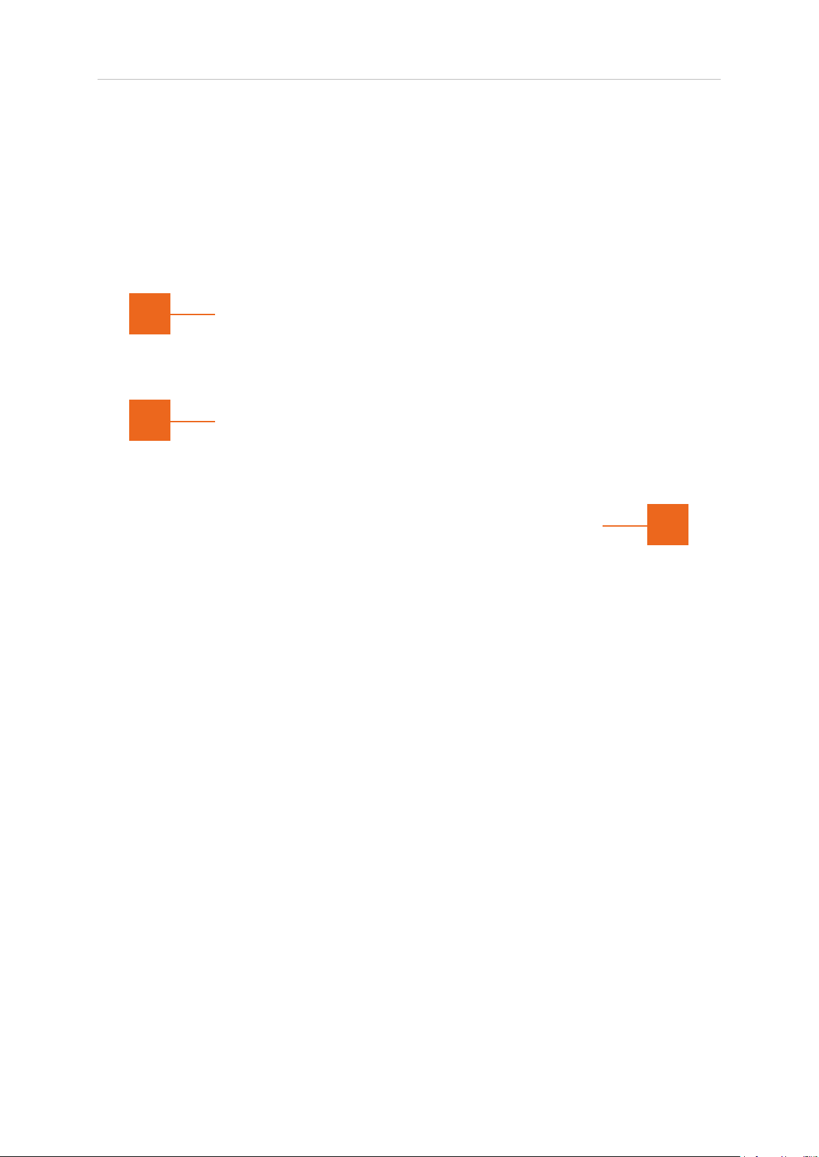
The SigMod interface provides an intuitive, self-adapting control surface showing a
logical signal-ow from left to right. While the interface can be congured to show many
different options, the fundamental principles of operation remain generally the same.
3
1
2
1 Interactive signal-ow. This shows the current available options for the chosen
settings. Buttons are interactive (highlighted when active), and numeric
boxes can be updated by either double-clicking to directly enter a new value, or
by click-dragging up/down to increase/decrease the value. The signal diagram
shown will change and resize automatically depending upon the modules
chosen via the settings panel.
2 Settings. Click this button to open the settings panel to add, remove, re-order or
change the function of modules in order to design a different signal-ow.
3 Utility controls. SigMod supports a number of standard utility controls. These
may be duplicated in some instances within the host DAW, however the controls
within the plug-in will operate ‘in place’ to provide seamless audio performance.
© 2019 NUGEN Audio
4
Contents
Page 5
SigMod Operation Manual
Interactive signal-ow
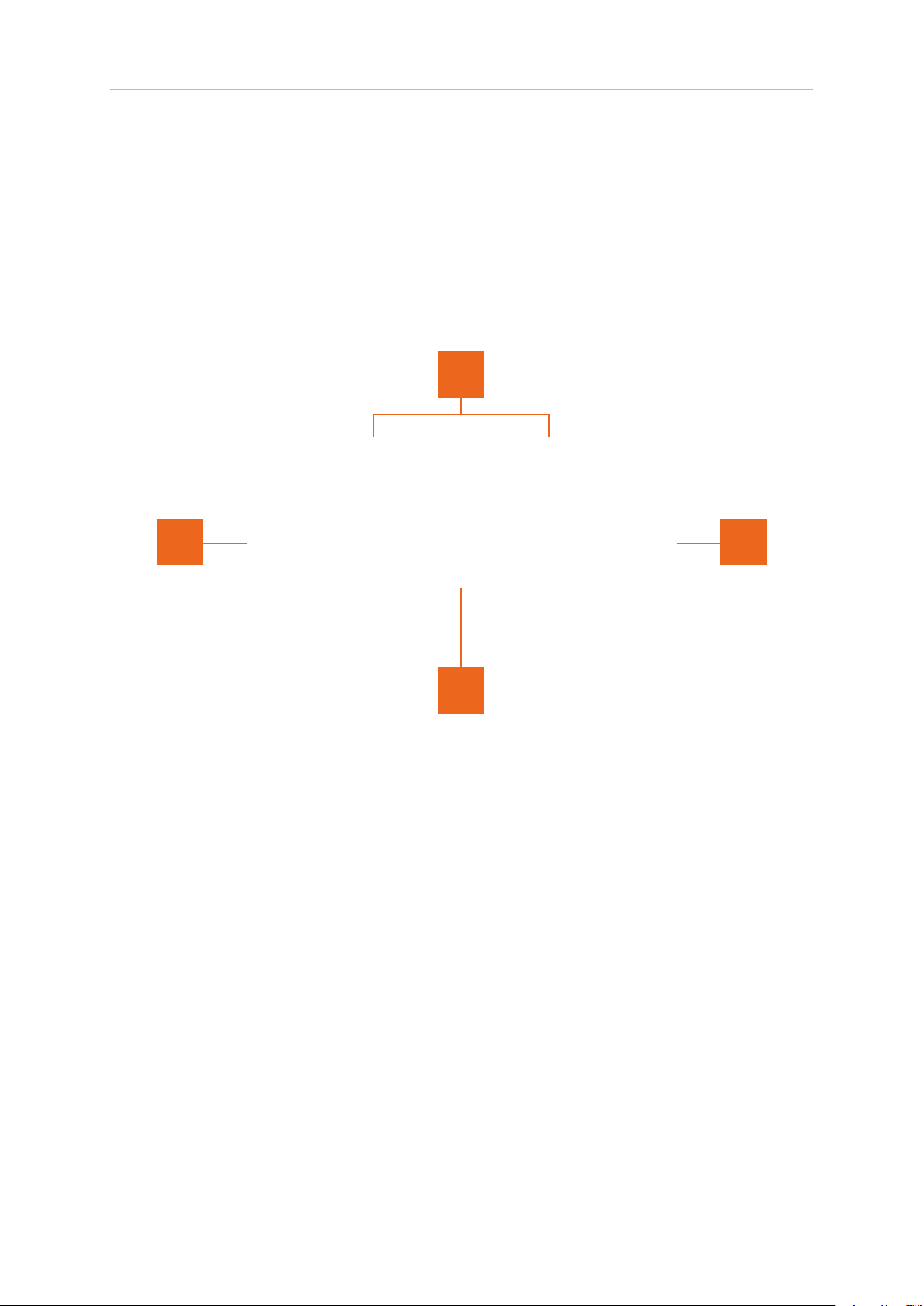
This area shows the functionality of the current patch, as an interactive signal diagram.
The Input and Output modules are xed, however a number of different modules may
be inserted in between, and the interface will recongure automatically, showing the
available options in the signal-ow.
3
1 2
4
1 Input. This is a xed module, congurable for stereo or mid/side input. Click to
activate/deactivate individual inputs.
2 Output. Fixed output module. The output automatically indicates the selected
signal encoding. Click to activate/deactivate individual outputs.
3 Modular signal-ow zone. This area is recongurable and reects the options
available for the modules chosen in the settings panel. Although the various
modules are different in application, operation is analogous.
4 Signal path. The active signal path is shown highlighted bold, and adapts to
reect the state of available controls. Alternative (inactive) routing is shown
in grey.
© 2019 NUGEN Audio
5
Contents
Page 6
SigMod Operation Manual
Settings
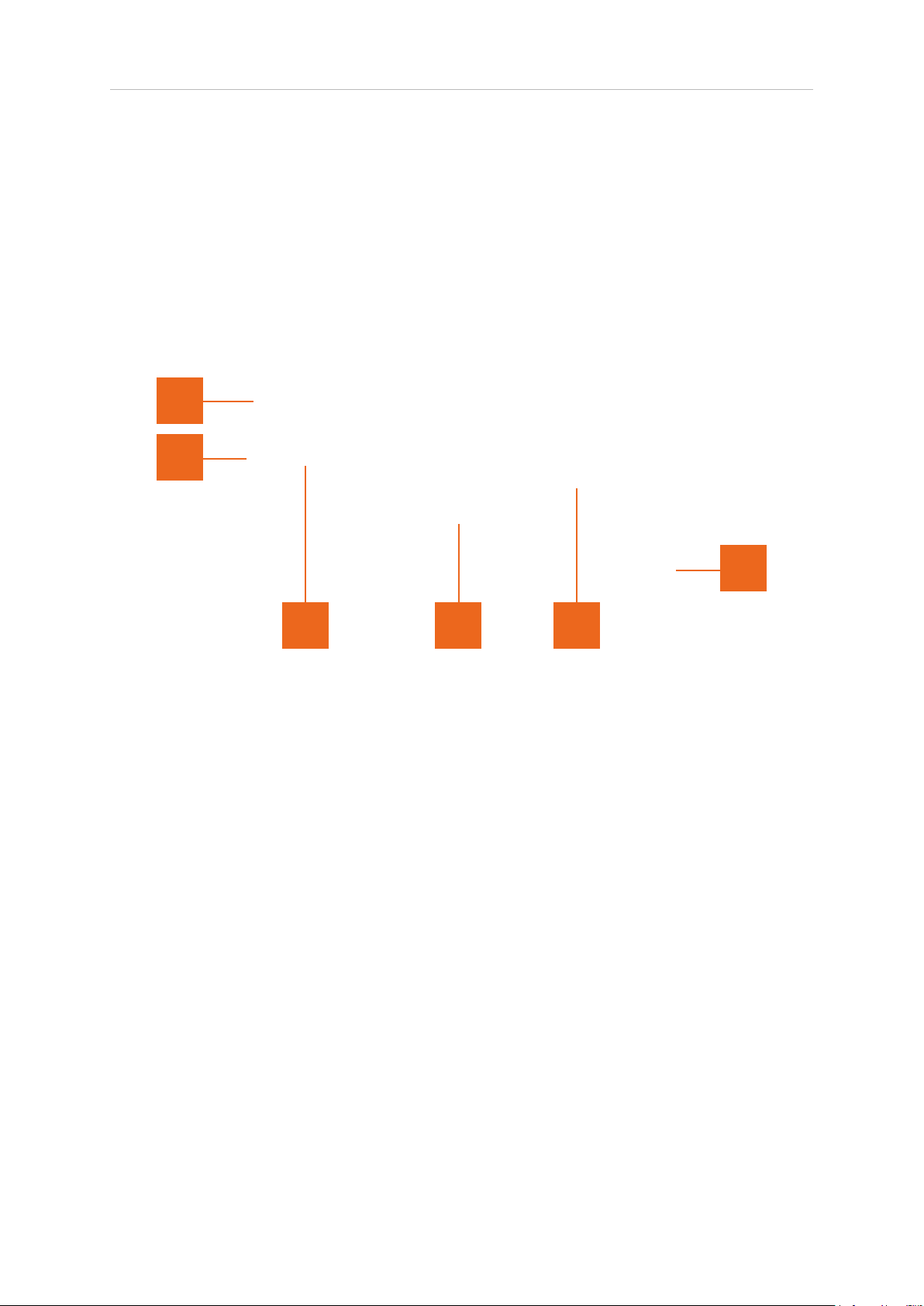
The settings panel is used to recongure the signal-ow for the desired operational
control. Modules may be added, removed, congured and re-ordered. The SigMod
interface will automatically resize to accommodate the modules selected.
3
2
1
4 5 6
1 Settings. Click to open/close settings panel.
2 Module name. In and Out modules are xed. Other modules may be
added/deleted or moved up to a maximum of ten additional modules.
3 Module parameter. Some modules have additional parameters which can be
used to change units of measurement etc.
4 Add new module. Click to insert an additional module at this point. Clicking the
‘+’ control will open a menu where a new module can be selected.
5 Remove module. Click the ‘x’ button to delete the associated module.
6 Move module. Click-drag left/right the ‘=’ control to change the position of the
selected module in the signal-ow.
When the signal-ow desired has been designed, close the settings panel by
deactivating the settings button to return to the main interactive signal-ow diagram.
© 2019 NUGEN Audio
6
Contents
Page 7
SigMod Operation Manual
Modules
Input
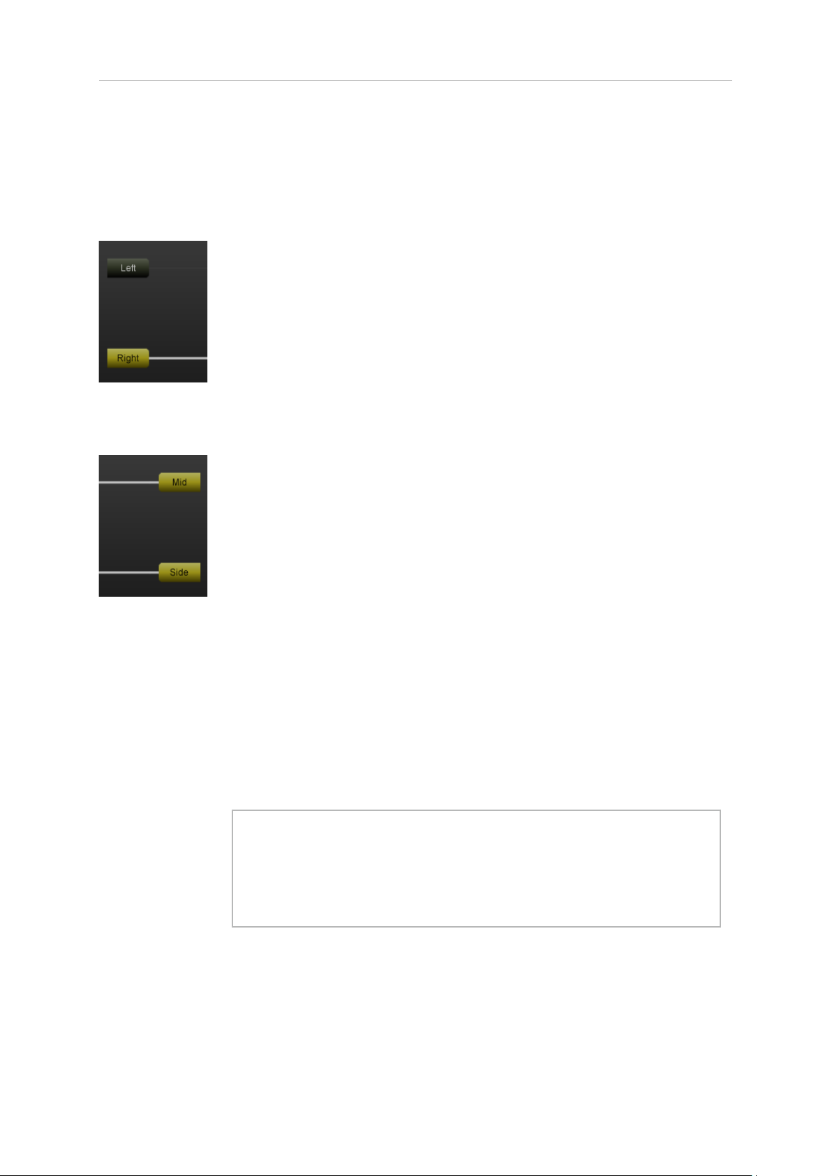
The Input module is a permanent module, xed at the beginning of
the signal-ow. Left/Right (or optionally Mid/Side inputs, selectable in
the options panel) are shown.
Inputs may be activated/disabled by clicking the appropriate button
control.
Output
Mid-Side
The Output module is a permanent module, xed at the end of the
signal-ow. Left/Right or Mid/Side outputs are automatically deduced
from the signal path settings.
Outputs may be activated/disabled using the appropriate button
control.
The Mid/Side module can be used to encode a Left/Right input to
Mid/Side, or decode a Mid/Side signal to Left/Right. The mode of
operation is determined by the settings of the Input module (above).
This is useful for Mid/Side signal monitoring, accessing the Mid/Side
signal components independently, or using Mid/Side recordings in a
traditional Left/Right stereo context.
Tip: Using two instances of SigMod either side of a 3rd party
stereo Left/Right plug-in with independent control over each
channel allows the 3rd party plug-in to be used in Mid/Side
mode. (Use the ‘Switch LR to MS’ preset on the rst instance of
SigMod, and the ‘Switch MS to LR’ preset on the second).
© 2019 NUGEN Audio
7
Contents
Page 8
SigMod Operation Manual
Mute/Solo
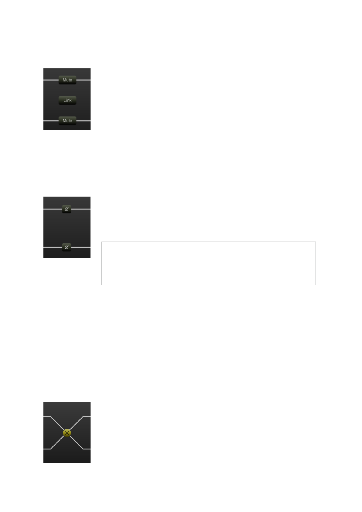
The Mute/Solo module introduces Mute or Solo controls into the
signal path.
Mute or Solo functionality is determined using the drop down option
in the settings panel.
The Link control links both functions together in the case of the Mute
control. Link is not available when the Solo function is active (null
control).
The Mute/Solo control can be useful for quickly auditioning either
side of a stereo signal, or in conjunction with the Mid/Side module, to
monitor the Mid and Side signals independently.
Phase
The Phase module introduces phase inversion switches (Polarity)
into the signal path.
Mono
Switch
These can be useful for checking the polarity of dual microphone
setups, xing phase inverted channels.
Tip: If you want to hear what an effect plug-in is doing to a signal
take a processed and unprocessed version of the signal, switch
the polarity of the original signal and mix back in to the effected
version to hear only the difference the effect makes.
The Mono module inserts a mono switch in to the signal path.
Activating the mono button adds the two signal components (L/R or
M/S) together.
Useful for checking mono compatibility of a mix, FX plug-in or synth
and phase coherence within dual mic set-ups.
The Switch module add the ability to switch channel components
over (L/R to R/L and M/S to S/M).
Channel outputs automatically reect and changes made.
© 2019 NUGEN Audio
8
Contents
Page 9
SigMod Operation Manual
Delay
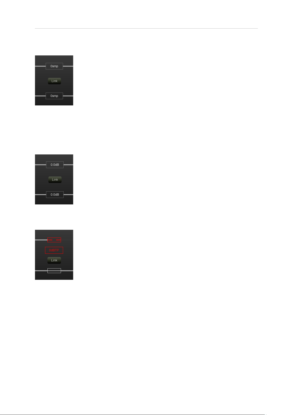
The Delay module adds the ability to delay signal components
independently. The Link control links the value of both components
together.
Double click to enter a value directly, or click drag up/down to
increase/decrease the value.
Units of ms samples or BPM locked ratios can be selected from the
settings panel.
This module can be useful for minimising phase issues & plug-in
delay compensation errors and adding tempo based offsets.
Trim
The Trim module adds the add a gain offset to each channel
component. The Link control links the value of both sides together.
Protect
Double click to enter a value directly, or click drag up/down to
increase/decrease the value.
This module can be used to correct minor imaging errors or modify
the stereo image by adjusting the ratio of Mid to Side components.
The Protect module monitors the audio signal level (in dBTP) and
automatically mutes the output level if the selected level is exceeded.
Several reset modes are available via the settings screen.
• Manual. (the signal path will need to be restored by clicking
the signal path in the plug-in).
• Auto (1, 2, 3, 5 secs). The plug-in automatically resets after
the chosen time period.
• Popup. A system popup window is triggered. This can be
useful if the plug-in is installed as a matter of routine
protection and it’s operation is forgotten. The pop up saves
hunting around for the reason behind the sudden signal
drop-out.
Placed on the master bus, the Protect unit can help protect both
equipment and hearing from sudden noise bursts due to feedback or
incorrectly functioning equipment.
© 2019 NUGEN Audio
9
Contents
Page 10

SigMod Operation Manual
DC Offset
The DC Offset unit detects or manually offsets incoming audio,
removing bias in the audio recording.
To automatically detect the offset, play affected audio and click the
‘Detect’ button. This will then listen to the incoming audio for a few
moments before calculating an appropriate value.
Crossover
The Crossover module allows the signal to be split at a specied
frequency, with the signal above or below the crossover point
(depending upon the lter chosen) passing through for further
processing.
The HPF (High Pass Filter) can be generally very useful in removing
unwanted low frequencies from microphone recordings, and
removing excessive sub-bass to increase digital headroom.
The NUGEN Audio Receive plug-in (included with SigMod installation)
can be attached to allow the removed signal to be sent to another
track for incorporation into the mix. This is useful for parallel
processing, adding effects to only part of the frequency spectrum or
adding different effects above and below the crossover frequency.
To use Receive:
• Insert Receive on an empty track, separate to the track
containing SigMod.
• Ensure that the Crossover module is connected to Receive.
• With the Crossover module switched on, the ltered audio will
be sent to the track containing Receive.
If no audio appears to be being sent to the Receive plug-in, ensure
that your DAW settings are set up to allow processing of audio
through plug-ins even when there is no audio present on the timeline.
Tap
The Tap unit is designed to allow audio to be easily duplicated to a second
track for parallel processing or monitor routing.
Multiple Tap units may be used to quickly set up complex routing and
overcome limited DAW sidechain or send bus capabilities.
The Tap unit works in conjunction with the NUGEN Audio Receive plug-in.
© 2019 NUGEN Audio
10
Contents
Page 11

SigMod Operation Manual
To use Receive:
• Insert Receive on an empty track, separate to the track containing SigMod.
• Ensure that the Tap unit is connected to Receive.
• With the Tap unit switched on, audio will be sent to the trackcontaining Receive.
If no audio appears to be being sent to the Receive plug-in, ensure that your DAW
settings are set up to allow processing of audio through plug-ins even when there is no
audio present on the timeline.
Insert
The Insert module allows the insertion of VST2, VST3 or AU (Mac) plug-ins
anywhere within the SigMod signalow. The addition of a ‘Dual Mono’
option in the settings screen allows for complex parallel processing within
SigMod, without the need to duplicate tracks or employ multiple busses.
The Wet/Dry controls will be shown when a plug-in slot is on. They can be
used to blend the incoming signal with the output signal processed by the
Insert effect. 0% is completely dry and 100% is completely wet. The Link
control is only available in stereo mode and links the value of the Wet/Dry
mix for each side.
To manage the plug-ins available within the module, click the ‘Gear’ icon to
open the available plug-ins menu.
Click ‘Scan’ to populate the plug-in list. You can also manually load a
plug-in by selecting ‘browse’, and browsing to your plug-in le. SigMod will
always scan the plug-in for compatibility before loading it. Loading a plugin manually will also add it to the plug-in list.
Click any of the top icons - active, inactive, VST2, VST3, AU - to lter the
plug-ins shown in the list below. If the button is highlighted then that type
of plug-in will be shown. SigMod also lters plug-ins by channel count, so
only Stereo plug-ins will be available in Stereo, and Mono plugins when in
‘Dual Mono’ mode. This option can be disabled by clicking the ‘Gear’ icon
and deselecting ‘Filter plug-in list by Channel Count’.
Clicking ‘Hide’ for a highlighted plug-in will send the plugin to the blacklist.
Clicking ‘Show’ for a highlighted plug-in will rescan and send the plug-in to
the active list.
To set the plug-in scan location, select the ‘Gear’ icon in the available
plugins menu, select the directory currently listed and browse to the new
location.
Once a plug-in has been inserted, clicking the plug-in name on the main
interface can be used to open the usual plug-in graphical interface to
adjust parameters.
© 2019 NUGEN Audio
Note: The Insert module only allows the insertion of VST2,
VST3 and AU (Mac) format effect plugins. Virtual instrument
(VSTi) plug-ins are not supported.
11
Contents
Page 12
SigMod Operation Manual
Utility controls
SigMod supports a number of standard utility controls. These may be duplicated
in some instances within the host DAW, however the controls within the plug-in will
operate ‘in place’ to provide seamless audio performance.
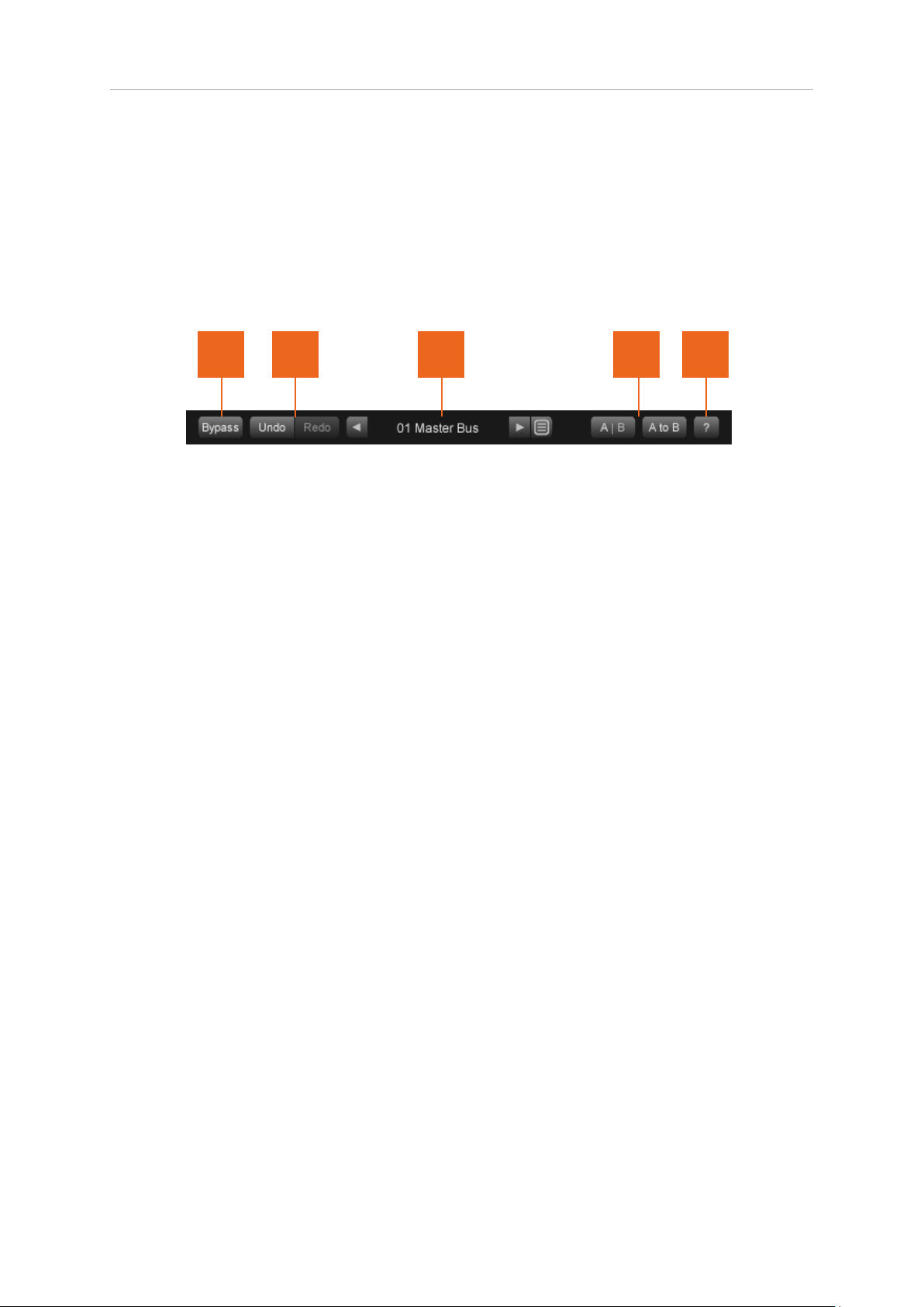
1 2 3
1 Bypass. This button bypasses the effect ‘in-place’. This allows for direct A | B
comparisons to be made with and without the effect, with out altering any other
processing in the chain.
2 Undo | Redo. Unlimited session undo and redo commands allowing the user to
step back and forward through processing modications.
3 Preset browser. Use the arrow buttons to step sequentially through the presets
or click the end control to open the preset menu to select from a list. Double click
the name to re-name session presets.
Preset management.
• The ‘Installed’ folder contains the factory presets. These cannot be
overwritten.
4 5
• User presets can be saved in the ‘User folder’. An ‘*’ symbol will be shown
against the preset name if the settings have been changed from the
saved version.
• Additional folders can be created using the ‘+’ button.
• Presets and folders can be organised by clicking the ‘…’ symbol which is
highlighted when the mouse pointer is placed over the folder/preset
name. Folders can be deleted, renamed and browsed using the
standard OS interface. Presets can additionally be moved and copied.
© 2019 NUGEN Audio
12
Contents
Page 13

SigMod Operation Manual
4 A | B and A to B (B to A). These controls switch data between the ‘A’ and ‘B’
memories for direct comparisons between two different sets of parameters.
The A | B control toggles between the A and B memories (current active memory
highlighted). The A to B (B to A) button transfers current settings to the memory
indicated, ie. From A to B or vice versa.
5 ? Opens the ‘About’ page, with access to credits and the product manual
(if installed).
General Functions
Holding down control (Ctrl) and clicking a control will return the control to the default
position (Win) or double click a control (OSX).
Holding down shift whilst moving a control will allow ne adjustment to be made.
© 2019 NUGEN Audio
13
Contents
Page 14

SigMod Operation Manual
Reporting a Problem
If you encounter a problem with any of NUGEN Audio’s products, please let us know, to
help us improve them.
Please email NUGEN Audio at [email protected] giving a clear explanation of
the problem. Please state how frequently you’ve experienced the problem. If there are
any particular steps you need to go through to see the problem, please detail these.
Please also state your operating system, and the rough specs for your machine (e.g.CPU speed, RAM) - in Windows XP you can get this information by rightclicking “My
Computer” and selecting properties.
Please be patient with any problems you may experience, particularly with products at
a beta stage of release. At NUGEN Audio we take problems with our software seriously,
and will endeavour to correct them as quickly as possible.
© 2019 NUGEN Audio
14
Contents
Page 15

SigMod Operation Manual
Version History
1.0 Initial release
1.1 New module ‘Insert VST3’ added
Delay Module BPM Tempo lock options added
Delay Module maximum delay time extended
Parameter value readout added
1.2 Hosting for VST2 and AU plugins added
Multiple Insert module instances enabled
Added Wet/Dry and Link controls for Insert module
Fix for delay bug
Updated text boxes
© 2019 NUGEN Audio
15
Contents
Page 16
www.nugenaudio.com
 Loading...