

Page 1

THE HOTBOX H.E.
Heater Suitable For Natural Gas at Inlet Pressure 20mbar
or Propane at Inlet Pressure 37mbar
USE, INSTALLATION & SERVICING INSTRUCTIONS
ALL INSTRUCTIONS MUST BE LEFT WITH THE USER FOR
SAFE KEEPING
MANUFACTURED by:
Nu-Flame Limited
Unit 4, Kimpton Trade & Business Centre
Minden Road, Sutton, Surrey SM3 9PF
Tel: 020 8254 6802
Fax: 020 8641 9992
Email: [email protected]
Country of Destination - GB & IE
Revision 16.6.16 RF
Page 2

2
CONTENTS
Section No Subject Page
User Section
- Contents Page 2
- Box Contents 2
- Fitting Kit Contents 3
1 Important Notes 4
2 Lighting & Controlling the Fire 5
3 Cleaning the Fire 7
4 Servicing 7
Installation Section
- Record Data 7
5 Installation Requirements 8
6 Appliance Data 8
7 Appliance Dimensions 8
8 Fret Requirements 9
9 Flue Requirements 9
10 Ventilation 9
11 Gas Supply 10
16 Fixing the Fire 17
17 Arrangement of the Fuel Effect 19
18 Testing, Commissioning & Use 22
19 Briefing the Customer 23
20 Servicing 23
21 Fault Finding Guide, Symptoms & Possible Cause 24
22 Diagram of Infrared Control System 26
- Guarantee 27
BOX CONTENTS
The Fire comes in 1 box containing the Fire with chosen Control and Fitting kit (see next page for fitting kit contents)
plus the chosen Fuel Bed Components (Coals or Pebbles). A Fret if ordered may come in a separate box.
Sections 12 - 15 are for the various installation applications -
Ensure you refer to the section relevant to your requirement
12 Class 1 & Lined Flue Fire Surround Application 11
Fireplace Construction
13 Pre-Cast Fireplace Application - Fireplace Construction 12
(Rebated or Purpose Built Fire Surround & Construction)
14 BS715 Shallow Flue Box with 5” Twin Wall Flue Application 14
(Fireplace or Hole in the Wall Construction
15 Hole in the Wall Application into Class 1 & Lined Flue 16
Builders Opening Construction
Page 3

3
THE HOTBOX H.E. FITTING KIT CONTENTS:
Cable Fixing Kit (2 # cables and fittings, 4 # eyebolts, 4 # screws and 4 # plastic plugs).
1 # Flue Restrictor.
2 # No.8 x 10mm pointed self tapping screws for the restrictor.
4 # Magnets for holding Front Trim on.
1 # 2,050mm length of 6mm x 4mm self adhesive silicone sealing strip.
1 # 10mm Back Nut & olive to connect 8mm copper pipe gas supply to the burner (via the isolation elbow).
1 # Set of Instructions / Warranty.
Page 4

4
1. - IMPORTANT NOTES
a. This appliance must be installed by a properly qualified (in accordance with National & Local Regulations) Installation Engineer.
b. The connection of this appliance and ventilation requirements (if any) are to be according to National & Local Codes.
c. This appliance does not normally require any purpose provided additional ventilation, however if it has been found necessary to
add a vent periodically check that it is free from obstruction.
d. Consult all Instructions before Installation and Use.
e. Do not throw rubbish on, or attempt to burn any materials on this appliance. Any Debris or Foreign Matter must be removed from
the fire.
f. The outer parts of this fire will become hot during use, cloths or combustible items must not be placed close to or on the fire. We
recommend that a Fireguard conforming to BS8423 should be used for protection of Young Children the Elderly, Infirm and Pets.
g. For Fires Installed above floor level, (Hole in the wall Fires), it is recommended that a means, (tactile separator/shelf or guard) is
provided to give abrupt warning to a person moving inadvertently towards the fire.
h. The appliance should be Serviced Annually in accordance with the Gas Safety & Uses Regulations.
i. Where the flue has been used for Solid Fuel it must be swept before Installation.
j. If at any time you smell gas or fumes turn the fire off and contact your Installer.
k. These Instructions must be left with the User for future reference.
l. During its first period of use any protective coatings and oils will burn out of the appliance and it is wise to ventilate the room for
the first hour of use.
m. This appliance is fitted with an oxygen depletion sensing system, which automatically shuts off the gas supply to the fire if the
oxygen level in the room is depleted, due to lack of primary air, or obstructed flue (blocked chimney) that would lead to
incomplete combustion of the gas. It must not be tampered with and only replaced with a genuine Nu-Flame ODS.
n. In the event that the fire shuts down for any reason, attempt to restart it. If there is a continuing problem, call in a properly
qualified specialist engineer.
o. There are no user replaceable parts in the appliance apart from the batteries, if a High Level or Thermatronic Electronic
Control System was ordered.
p. The chimney should be regularly checked to ensure that all the products of combustion are entering the flue & that there is no
build up of soot. If there is, the appliance must be serviced.
q. Coal or Pebble fuel effects, manufactured from refractory fibre, are supplied with this appliance. Do not use real coals or pebbles
as this is dangerous. If the simulated fuel bed components need renewing please obtain suitable replacements from a Nu-Flame
Stockist. Light coloured Pebbles can be prone to discolouration, this is quite normal.
r. The fire must be installed in accordance with the rules in force and these Instructions it must be installed into a fireplace or
builders opening as detailed in these Instructions.
s. No combustible materials e.g. curtains must be closer than 500mm to the fire.
t. For Fire Surround Applications a 150mm (6”) combustible shelf can be fitted above the fire provided it is 150mm above the
Fireplace Opening.
u. The Fire can be installed into a suitably designed fire surround with a 150ºC Rating.
v. Explain to the customer that over time some wall staining will occur above the fire and this is due primarily to particles of dust
present in the hot convection air circulating up and over the fire/surround and sticking to the wall.
It is quite normal for the fire to make popping and burbling sounds when in use, as would a solid fuel fire.
.
THE HOTBOX H.E.
USER INSTRUCTIONS
Page 5

5
2. - LIGHTING & CONTROLLING THE FIRE
General
The fire is available with 4 Control Options: a Manual Control (Fire is lit and adjusted manually), a side fitted 2 Button High Level Control
(Fire when lit can be controlled with the Push Buttons), a side fitted 3 Button High Level Control (Fire can be lit and controlled with the Push
Buttons) or Thermatronic Radio Frequency Electronic Control System (Fire is lit and operated with the Handset).
Some Models also have a Coal / Coke Effect Lever System see 2.7
2.1 - LIGHTING & CONTROLLING THE FIRE – MANUAL CONTROL
Remove the Ash Pan Cover to get access to the Control Knob used to operate the Fire.
a. Switching On/Ignition. Depress t he co ntr ol k nob & turn counter clockw ise. Gas will flow to the Pilot Burner (Pilot Burner is visible
looking down through the glass at the left side), the Piezo Igniter will give off first one, then, as you turn, a second high voltage
spark & the Pilot Burner will Light. (More than one attempt may have to be made on first lighting.)
Keep the Control Knob depressed for approximately 10 seconds to heat up the Thermocouple.
Turn the Control Knob fully counter clockwise to release gas to the Main Burner.
b. Control of Gas Flow. Turni ng t he Con tro l Kn ob c loc kwi se reduces the g as fl ow f rom Maxim um t o th e Pre-Set Minimum Setting.
Turning between Maximum & Minimum does not actuate the Piezo Igniter. The Control Valve can only be turned on to the Pilot
setting by depressing the control knob & turning it to the pre-selected pilot position.
c. Switching Off. Pres s th e Control Knob in at the Pilot Posit ion & tu rn Cl ockwis e to Off.
2.2 - LIGHTING & CONTROLLING THE FIRE – 2 BUTTON HIGH LEVEL CONTROL
Requires Pilot Ignition First.
The side trim positioned High Level Control System is a battery operated gas fire control system that uses push buttons linked to a main
control at the base of the fire. This control system is used with an oxypilot and has all the safety features required by law and CE approval.
Once the fire is lit by operating the Control behind the Ash Pan Cover the settings can be controlled by the 2 Push Buttons on the upper
right side of the Trim.
Using the System
Remove the Ash Pan Cover to get access to the Control Knob used to operate the Fire.
a. Switching On/Ignition. Depress t he ri ght con tro l knob & turn counter clockwise. Gas will flow to the Pilot Burner
(Pilot Burner is visible looking through the fender, under the flue bed, at the front right hand corner), the integral Piezo
Igniter will also give off a high voltage spark & the Pilot Burner will Light. (More than one attempt may have to be made
on first lighting.)
Keep the Control Knob depressed for approximately 10 seconds to heat up the Thermocouple.
Turn the Control Knob fully counter clockwise to release gas to the Main Burner.
b. Control of Gas Flow Using the Side Trim Push Buttons. Press the lowest button to g radu ally red uce the gas flow
from Maximum to the Pre-Set Minimum Setting, you will hear the motor turning the control. Keeping the Lower Button
depressed will eventually turn the main burner off leaving the pilot alight.
To relight the main burner or increase the heat setting from low, press the Upper Button to achieve settings between
low and high. When the fire has reached high the control under the fire will click repeatedly, release the button.
c. Switching Off. Remo ve the As h Pan Cover and turn the right Control Knob Clockw ise to Off.
d. Battery Replacement . The Batter ies s hould b e repl aced every seaso n, you will n oti ce th ey n eed chan ging as
gradually the Push Buttons cease to operate the Control.
e. Changing the Batteries. Remove the As h Pan Cover and you will f ind the B attery Box on the l eft hand side.
Pull towards the front taking care not to strain the connecting wire. Using a small screw driver remove the screw, slide
off the cover and take out the Batteries. Replace with 4 x AA good quality alkaline batteries, operate the Push Buttons
to check the Batteries are fitted correctly.
Note: Only Change The Batteries When The Fire Is Cold
2.3 - LIGHTING & CONTROLLING THE FIRE - 3 BUTTON HIGH LEVEL CONTROL
The 3 Button High Level Control Lights the Pilot and Controls the Fire.
The side trim positioned High Level Control System is a battery operated gas fire control system that uses push buttons linked to a main
control at the base of the fire. This control system is used with an oxypilot and has all the safety features required by law and CE approval.
Note: The Centre Button is both the Ignition and Off Button.
Using the System
a. Ignition. Sim ult aneou sly press and hol d the Centre Bu tto n un til a sho rt ac ous tic signal c onfirm s that the sequenc e
has begun, then release the buttons. Continuous audible signals confirm that ignition is in progress. When pilot ignition is
confirmed the motor will open the valve to maximum flame height – this takes about 30 seconds.
When the fire is first operated and on occasions when the fire has not been used for some time the Pilot may not light
after pressing the Centre Ignition Button even though the acoustic sound may have been heard. On these occasions it may
be necessary to repeat the sequence a number times to light the pilot. This is quite normal.
b. Flame Height Adjustment. Pres s th e bot tom dow n arr ow b utt on unti l the flame height is at the desired po sition .
If you try to go beyond the preset low flame minimum height the fire will turn off leaving the pilot burner alight
(This is the standby position). You will learn from experience the minimum preset flame height.
c. Relighting the Fire. To relight the fi re from t he standb y p osition, or to increase the flam e heig ht f rom low flam e, pres s
the top up arrow.
Please note that you can have the flame height anywhere between maximum and preset low.
For fine adjustment simply tap the up or down arrows.
d. Switching Off. Pres s the centre bu tton.
Page 6
6
e. Battery Replacement. The B atter ies s hou ld b e repl aced every season, you will notice they n eed chan gin g as g radu ally th e
Push Buttons cease to operate the Control.
f. Changing the Receiver Batteries. To c hang e the Receiver Batteries remo ve the As h Pan Co ver an d locate the elec tro nic
receiver box, underneath the fire on the left hand side. Slide open the plastic cover to gain access to the battery compartment.
You can detach the Receiver by pulling it off its Velcro Pad to make access easier but remember to put it back in the same
position. Replace with 4 x AA good quality alkaline batteries, operate the Push Buttons to check the Batteries are fitted correctly.
Note: Only Change The Batteries When The Fire Is Cold
2.4 - LIGHTING & CONTROLLING THE FIRE - THERMATRONIC RF CONTROL
The Thermatronic Control System is a battery operated gas fire control system that uses a microprocessor to provide the working
sequences needed by the fire, and when used with an oxypilot has all the safety features required by law and CE approval.
Commands are accepted by the microprocessor when buttons are pressed. An audible beep means that the command is received,
and the push button should immediately be released.
Using the System
Control can only be achieved if the Handset is pointed at the Fire.
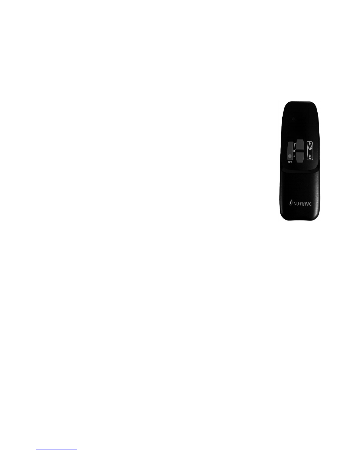
The red light will flash each time you press the Handset.
a. Ignition. Sim ult aneou sly press and hol d the red button and the ri ght upp er bu tto n (linked by lin e) until a
short acoustic signal confirms that the sequence has begun, then release the buttons.
Continuous audible signals confirm that ignition is in progress.
When pilot ignition is confirmed the motor will open the valve to maximum flame height – this takes about
30 seconds.
b. Flame Height Adjustment. Pres s th e smal l fl ame bu tton until the flame height is at the desired pos ition.
If you try to go beyond the preset low flame minimum height the main burner will turn off leaving the pilot
burner alight (this is the standby position).
You will learn from experience the preset low flame minimum height.
You will learn from experience the minimum preset flame height.
c. Relighting the Fire. To relight the fi re from t he standb y p osition, or to increase the flam e heig ht f rom low
flame press and hold the large flame button until the desired flame height is achieved. Please note that
you can have the flame height anywhere between maximum and preset low.
For fine adjustment simply tap the small or large flame buttons.
d. Switching Off. Pres s the red/off button on the Hand set.
2.5 - GENERAL
a. Battery replacement is recommended at the beginning of each heating season, or when an acoustic error
message sounds during ignition.
b. Error Message – Long signals (0.8 second tone – 0.2 second break) during ignition – probable cause - batteries
in electronic receiver box are nearly discharged.
c. Error Message – 5 second continuous tone – probable cause – cable disconnected or on/off switch on valve is in off position.
d. Batteries - Electronic Receiver Box - 4 x AA good quality alkaline - Handset - 1 x PP3 good quality alkaline.
e. To change the Handset battery slide open the plastic panel on the back of the Handset.
f. To change the Receiver Batteries remove the Ash Pan Cover and locate the electronic receiver box, underneath the fire on the left
hand side. Slide open the plastic cover to gain access to the battery compartment. You can detach the Receiver by pulling it off its
Velcro Pad to make access easier but remember to put it back in the same position.
Note: Only Change The Batteries When The Fire Is Cold
2.6 - RESETTING THE MERTIK MAXITROL LOGIC CIRCUITS - IF THE HANDSET DOES NOT WORK
ONLY APPLIES TO THE THERMATRONIC HAND HELD RADIO FREQUENCY CONTROL
Basic Reset - It s ometimes happens that (such as when t he han dset but ton s are p ressed out of sequenc e) the fire s top s
working because the logic circuits get confused and need to be reset.
To do this, simply remove the 4 x AA batteries from the Receiver Box (see section 2.4f above), wait for 1 minute and then refit the
batteries. Wait for another minute and then point the handset at the fire and press the red/off button. Wait for another minute and then
start the fire as normal. If the fire does not start repeat the resetting procedure. If the fire still does not work a Full Reset can be tried.
Full Reset - If you obtain a new handset the control system will need to learn the handset’s unique code via a Full Reset. Also, if the
fire is not working and the Basic Reset has not worked a Full Reset can be carried out:
Remove the Ash Pan Cover and locate the electronic Receiver Box.
Locate the Reset Hole on the side of the Receiver and using a pen press and hold in the Reset button until you hear two beeps.
The first beep is short and the second beep is long. After the second beep release the Reset Button.
Now on the Handset, within the next 20 seconds press and hold the Small Flame Button until you hear two additional short beeps
confirming the code is set in the Receiver.
If you hear one long beep the Code as not been set so repeat the procedure.
If after carrying out the above procedure the situation is not corrected it will be necessary to contact your Installer.
Note: For the Installation/Service Engineer - Resetting of the Handset & Control System is also covered in Section 21.1 page 24.
Page 7

7
2.7.- COAL-COKE EFFECT LEVER
Note : This Feature i s not used on either the Natural Gas Peb ble Fi re or the Pr opane Fires .
The Natural Gas Coal Fire Model is fitted with a control lever to enable different flame effects to be created. With the lever pushed-in
the flames will be quite yellow replicating a Coal Fire Flame Effect. With the lever pulled-out the flames will be more blue replicating
a Coke Fire Flame Effect. The Coke Fire Flame Effect setting provides the hottest and most efficient Heat Output for the Fire.
a. Remove the Ash Pan and at the upper centre of the opening you will see the black Coal-Coke Lever. Push the lever in for the
Coal Effect setting, pull the lever out for the Coke Effect setting.
! IMPORTANT ! On the Coal Setting, the Yellow Flames may cause some sooty deposits to form and to reduce this we
recommend changing to the hottest Coke Setting.
! TIP ! On the Coke Setting the Fire Produces More Heat and is operating at its most Efficient Heat Setting.
3. - CLEANING THE FIRE
a. Allow to cool before cleaning.
b. The outer surfaces of the fire can be cleaned with a damp cloth and lightly polished with a duster, do not use abrasive cleaners.
For Stainless Steel finishes we recommend a small amount of Baby Oil.
4. - SERVICING
a. The fire should be Serviced Annually in accordance with the Gas Safety & Uses Regulations.
b. This fire contains no User Serviceable Parts apart from the batteries which are only used with the High Level and Thermatronic
Control System options.
c. Servicing must be carried out by a Registered Installer.
d. For Servicing or Spare Parts contact your Installer quoting the Fire Name, Model and Serial Number, which can be found on the
Data Badge. To find the Data Badge/Plate; with the fire cool remove the Ash Pan Cover, the Data Badge can be found at the
base next to the Control Knob.
e. In the event that the fire shuts down due to any reason, attempt to restart it. If there is a continuing problem, call in a properly
qualified specialist engineer.
f. The Matrix in the fire is a Moulded Ceramic Fibre component incorporating Silicone Binders and you may notice that it develops
cracks during operation. This is natural shrinkage caused by exposure to high temperatures and is quite normal for the material
and will in no way affect the operation of the fire.
RECORD DATA TO BE COMPLETED & KEPT BY USER:
PLACE OF PURCHASE ..................................................................…………………… DATE ……....................
ADDRESS & TEL. NO. …………….......................................…..................................................................................
.................................................................................................................................………………………..........….....
.................................................................................................................................………………………..........….....
APPLIANCE SERIAL NO. ..............................................
INSTALLED BY ........................................…………………………… GAS SAFE REG. NO. ..............................
THE HOTBOX H.E.
INSTALLATION & SERVICING INSTRUCTIONS
Page 8

8
5. - INSTALLATION REQUIREMENTS
THIS APPLIANCE MUST BE INSTALLED AND SERVICED BY A PROPERLY QUALIFIED, (IN ACCORDANCE WITH LOCAL &
NATIONAL CODES), INSTALLATION ENGINEER.
It is the Law in the UK that All gas appliances are installed by a competent person in accordance with the GAS SAFETY
(INSTALLATION AND USE) REGULATIONS 1998 (As amended), the relevant British Standards for Installation work, Building Regulations, Codes of Practice and these Instructions. In the UK a Registered Installer is deemed competent. In the
Republic of Ireland, all Irish Standards, Local Codes and Bord Gais recommendations should be adhered to.
The Installation should also be carried out in accordance with the following where relevant:
1. BS5871 Part 2 2. BS5440 Parts 1 & 2 3. BS6461 Parts 1 & 2 4. BS6891 5. BS8303 6. BS EN 1856 7. BS715
Building Regulations and Standards issued as relevant by the Department of the Environment or the Scottish Development
Department.
In the Republic of Ireland Installation should be carried out in accordance with IS813, ICP3, IS327, Building Regulations, Codes of
Practice, these Manufacturers Instructions and any Rules In Force.
Particular Reference should be made to the Ventilation Requirements, for the UK this Appliance would not normally require any
additional purpose provided ventilation, for the Republic of Ireland ventilation should be in accordance with IS813 Domestic Gas
Installations.
Failure to comply with the above could leave the Installer Liable to Prosecution and Invalidate the Warranty.
IMPORTANT
BEFORE PROCEEDING WITH THE INSTALLATION READ THESE INSTRUCTIONS CAREFULLY. THESE INSTRUCTIONS
SHOULD BE LEFT WITH THE USER FOR SAFE KEEPING AND FUTURE SERVICING. PRIOR TO INSTALLATION ENSURE
THAT THE GAS TYPE AND PRESSURE ARE AS STATED ON THE APPLIANCE DATA BADGE.
6. - APPLIANCE DATA
a. Gas Type: See Data Plate (Natural Gas at 20mbar or Propane 37mbar).
b. Burner Pressure: Natural Gas 18.0mbar cold. Propane 35.8mbar cold.
c. Control Systems: Manual or High Level (Push Button) or Thermatronic (Fully Sequential) Control System operated by Handset
pointed at Receiver.
d. Fire Safety: Oxygen Depletion & Flame Failure Device.
e. Ignition: Manual-Integral Piezo Igniter, High Level-Integral Piezo Igniter, Thermatronic-Full Sequential Control.
f. Inlet Connection: 8mm Compression Fitting to Gas Isolation Elbow.
g. Categories: I2H & I3P
h. Injector: Natural Gas (G20) - 480 Multi hole. Propane (G31) - 210 Single hole.
i. Heat Input: High: Natural Gas (G20) - 6.95kW Gross (6.26kW Nett). Propane (G31) - 6.65kW Gross (6.12kW Nett).
j. Heat Input: Low: Natural Gas (G20) - 2.0kW Gross (1.8kW Nett). Propane (G31) - 2.0Kw Gross (1.8kW Nett).
k. Efficiency Class: 2. The Efficiency of this appliance has been measured as specified in BS7977-1:2009, the results obtained
were: Natural Gas 58.6% Gross (65.0% Nett), Propane 56.6% Gross (65.0%Nett). The test data has been certified by BSI
Group (0086) and can be used in the UK Government’s Standard Assessment Procedure (SAP) for Energy Rating of Dwellings.
l. Heat Outp ut: High : Natural Gas (G20) - 4.1kW. Propane (G31) - 3.9kW.
m. Heat Ou tput: Low : Natu ral Gas (G20) - 1.1kW . Propane (G31) - 1.1kW.
n. Pilot ODS Type: Natural Gas (G20) - P448 . Propane (G31) - P449 .
Designs may vary; the diagram above is to show important dimensions
7. - APPLIANCE DIMENSIONS
Additional detail for “Hole in
the Wall” frames
With 3 sided frame for fireplace use.
Page 9
9
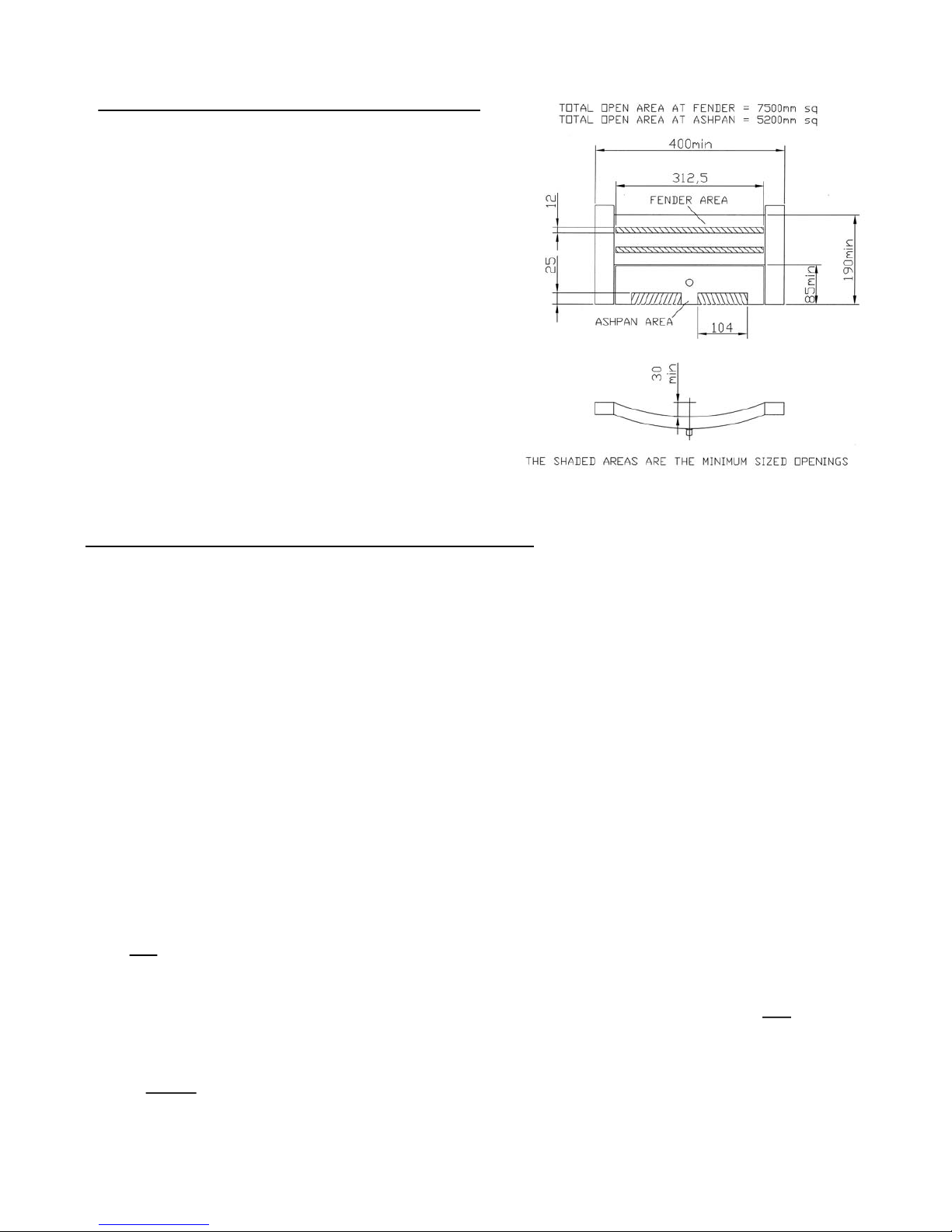
8. - FRET REQUIREMENTS
!IMPORTANT NOTE! THE FRET CAN AFFECT THE SAFE OPERATION OF THE FIRE
9. - FLUE REQUIREMENTS
These checks MUST be made before constructing the Builders Opening
The Appliance is suitable for Installation into the following types of Flue:
a. Conventional Stone/Brick Built Flue (Class 1) with a minimum cross sectional dimension of 175mm (7”) with a minimum effective
height of 3 meters.
b. The flue MUST be free of any obstructions. Any dampers or restrictors MUST be removed. Some dampers are impractical to be
removed; therefore they MUST be fixed in some way in the OPEN position.
c. The chimney/flue should be swept if it has been used for solid fuel.
d. A Flue Lined with a 5” Flexible Flue Liner connected to a Register Plate fitted and sealed at the top of the Builders Opening with a
minimum effective height of 3 meters.
e. A Pre-cast Flue with Starter Blocks conforming to BS1289: 1975, 1986, or 1989 or BS EN1858 and having a minimum cross
sectional flue of 198mm by 67mm and Starter Blocks providing 115mm deep by 304mm wide with a minimum height of 555mm.
No part of the Pre-cast Flue must be less than 63mm.
f. The Fire may be used in conjunction with a Fully Sealed Rebated 150C rated or Equivalent Purpose Built Fire Surround.
g. Any Pre-Cast Flue must be Sound and Free from Obstructions (Mortar Fangs or Protrusions into the Flue Way) and have an
effective height of over 3 meters.
h. For Pre-cast Flues - ensure the walls are dry lined over the route of the flue and no dabs or battens are in direct contact with the
flue blocks otherwise wall cracking will occur as detailed in BS 5440 Pt 1 2008.
i. A Purpose Designed Flue Box to BS715 fitted with a 5” twin walled flue with a minimum effect height of 3 meters to BS EN 1856.
Details are available from your authorised supplier.
j. Ensure that only one fireplace is served by the flue system.
k. Ensure that the chimney/flue is continuous from inlet to termination.
l. Ensure that the chimney/flue is structurally sound, so that combustion products do NOT come into contact with combustible
materials outside the chimney.
m. CHECK FLUE PULL. Apply a s moke matc h or smo ke generato r to the flue o peni ng at heart h lev el and observe s moke. If
there is a definite flow into the flue aperture, proceed with installation. If there is not a definite flow into the flue aperture, preheat
the flue for approximately 10 minutes and re-test. If there is not a definite flow towards the flue aperture the flue may need
attention.
DO NOT FIT THE APPLIANCE, SEEK EXPERT ADVICE.
10. - VENTILATION
a. No additional purpose provided ventilation is normally required for the fire when installed in the UK; however this must be
confirmed by the Spillage Test, see Section 18.2.
b. For other Countries refer to National Regulations and Local Codes.
c. This appliance is fitted with an oxygen depletion sensing system, which automatically shuts off the gas supply to the fire if the
oxygen level in the room is depleted, due to lack of primary air, or obstructed flue that would lead to incomplete combustion of the
gas. It must not be tampered with and only replaced with a genuine Nu-Flame ODS Pilot.
These checks MUST be made before selecting a suitable Fret
a. The Important Minimum Open Area’s (for airflow) of the Fret are
shown in the diagram, with the minimum dimensions .
b. The Minimum Open Area at the base of the Ash Pan Cover is
5200mm sq equally shared between two openings, they must be
at the base of the Ash Pan Cover.
c. The Minimum Open Area in the Fender area (above Ash Pan Cover)
is 7500mm sq which can be provided through one or more slots.
d. The correct height to the Upper most part of the Fret must be
190mm, to align with the Fuel Bed.
e. The opening for the Ash Pan Cover area must be 85mm minimum
height to allow access for operation of the Controls.
f. The Fret will have to be curved at the back and must be checked to
ensure it does not foul the Matrix of the Fuel Bed. It should
also touch the Trim.
Page 10

10
11. - GAS SUPPLY
It Is Recommended to Check The Next Section as Building Work May Affect the Gas Supply Routing.
a. Carry out a gas soundness test before working on the gas supply.
b. Gas supply provision should be made in accordance with the latest Gas Safety (Installation and Use) Regulations as amended.
c. Confirm that the fire has been supplied for the correct gas to be used by checking the Data Badge in the base of the fire.
d. A route for a concealed gas supply is provided through a hole in the rear of the fire, at a position of 95mm to the left of the centre
of the fire and 49mm up from the base of the Fireplace/Builders opening. An isolation elbow is provided at the control inlet. Your
8mm gas supply pipe needs to protrude through the back of the convector box by approximately 190mm to achieve a neat
connection onto the back of the isolator elbow on the burner. (This applies to All Control Options.)
e. Where the gas supply passes through walls, floors, voids, concrete and wall cavities the supply should be sleeved.
f. Determine the gas supply pipe size required taking into account any other gas appliances.
g. Determine where the gas supply pipe needs to terminate and fit the 8mm compression isolation/pressure test elbow provided.
h. In common with all other gas appliances, dirt and debris in the gas system can block the valve and gas injectors on this
appliance, and faults caused by this are not covered by the guarantee.
Therefore it is important that all gas pipes must be purged of both air and debris.
i If you suspect that there may still be dirt and/or debris in the gas system, fit a filter in the pipeline, before the gas isolation/
pressure test elbow.
J. Do not use jointing compound on any compression fittings on the fire. The use of jointing compound on the compression joints
on this appliance will possibly invalidate the guarantee, as it can get into the control mechanism and cause a malfunction.
k. Seal off the isolation/pressure test elbow and check all gas connections for gas soundness before proceeding to fit the fire.
! IMPORTANT NOTE ! Always reseal the pressure test point and check that it is gas tight. (This accounts for a lot of
recalls.)
The Installation Application Options Are:
12.0 Installation into a Class 1 or Lined Flue with a 150ºC rated Fire Surround fitted into a Suitable
Fireplace Opening or 16” Chairbrick.
13.0 Installation into a Pre-cast Flue Fireplace. (Rebated Fire Surround Rated 150ºC or Purpose
Built Surround Extension.)
14.0 Installation into a BS 715 Shallow Flue Box with Twin Wall 5”Flue, False Chimney Breast with
either a 150ºC rated Fire Surround or part way up the wall as a Hole in the Wall Installation with
Slips & Shelf.
15.0 Installation into a Hole in the Wall application with a Class 1 or Lined Flue requiring a Purpose
made Builders Opening.
Sections 12 - 15 are for the various Installation Applications -
Only one will apply.
! IMPORTANT NOTE !
The chosen installation should have
been predetermined and arranged before installing the fire.
Ensure you refer to the section relevant to your requirement.
Page 11
11
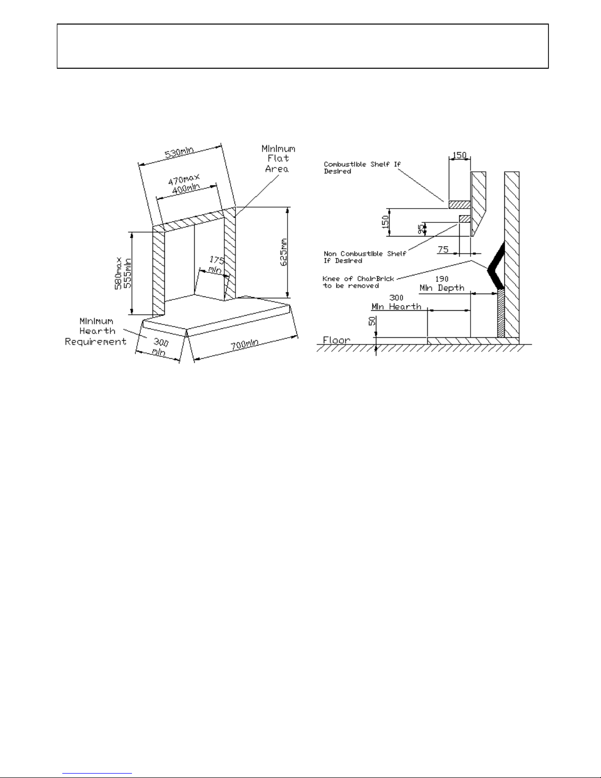
There must be no combustible materials inside the fireplace opening.
12.1 - FIRE SURROUND APPLICATIONS
12.2 - FIRE SURROUND REQUIREMENTS (See diagram in Section 12.1)
a. If the Fire is to be fitted into a purpose made Fire Surround it must have a temperature rating of 150ºC.
b. Where the fire is to be fitted in to an exis ting 16” chair bri ck a minimum depth of 175mm i s req uired & t he Kn ee of t he
Chairbrick must be removed. If sufficient depth is not available the chairbrick will have to be removed, or extra depth added to the front.
c. Where the depth available is greater than 240 mm the fire can be fitted without changing the chairbrick.
d. The Fire requires a non-combustible hearth of at least 12mm thick.
e. The surface of the hearth must stand at least 50mm above the floor and level with the fireplace opening.
f. The hearth must project at least 300mm in front of the fireplace opening and 150mm either side (700mm minimum hearth width).
g. The base of the fireplace must be flat, level and square to the face of the fireplace opening.
h. The Surround must cater for a minimum flat surface around the Fireplace Opening allowing 625mm high by 530mm wide.
This is essential in order to achieve a good seal between the face of the surround and the sealing flanges of the fire.
i. The Fire Surround must be fully sealed to the Fireplace Opening to ensure a good flue seal.
j. The Fireplace Opening should have provision for a gas supply through the rear, see Section 11 Gas Supply.
k. The High Level and Thermatronic Control Systems are fitted with Electronic Equipment, which is sensitive to dampness and high
humidity so it is very important that any rendering/building work is allowed to thoroughly dry out before Installation.
! IMPORTANT NOTE ! Dry lined walls – ensure that any air gaps between the back of the plasterboard and wall are sealed
around the builders opening or fireplace as this can affect flue pull and wall staining.
12.3 - CLEARANCES TO COMBUSTIBLE MATERIALS AND SHELVES (Ref: Diagram in Section 12.1)
a. A non combustible shelf can be fitted above the fire and should be positioned at least 95mm above the builders opening. We
recommend the depth of the shelf should be a maximum of 75mm as anything deeper will reduce convection air and the
efficiency of the fire. For deeper non-combustible shelves they must be raised a further 25mm for every extra 25mm of depth.
b. A 150mm combustible shelf can be fitted above the fire but must be positioned at least 150mm above the builders opening. For deeper
combustible shelves they must be raised a further 25mm for every extra 25mm of depth.
c. Any combustible sidewall must be at least 500mm from the inside of the builders/fireplace opening, however with a combustible fire
surround it can be 150mm from the inside of the builders/fireplace opening provided it does not protrude more than 150mm and must be
increased by 25mm for every extra 25mm of depth.
d. With all heating appliances, soft furnishings, decorations and wall coverings may discolour or scorch if placed too close.
e. No combustible material, e.g. curtains must be closer than 500mm to the builders opening.
f. Any combustible wall claddings (wall paper) must be cut back to a height of 750mm and 300 mm either side of the Fireplace Opening.
g. Due to the heat output of The Hotbox H.E. it is not recommended to use blown vinyl wall covering around the fire.
NOW PROCEED TO SECTION 16 - FIXING THE FIRE.
12. CLASS 1 OR LINED FLUE FIRE SURROUND APPLICATION
FIREPLACE CONSTRUCTION
Fireplace Minimum Requirements
Fireplace Construction
With 16” Chairbrick
Page 12
12
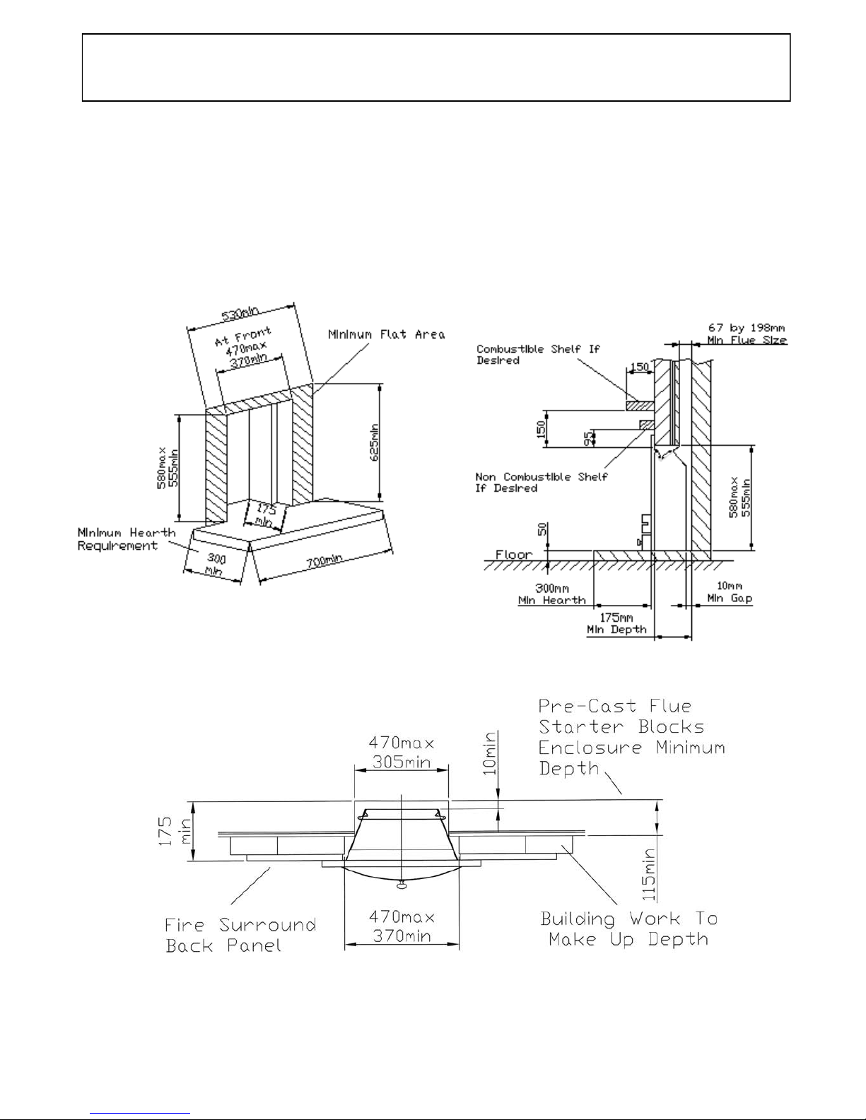
There must be no combustible materials inside the builders opening.
13.1 - EXISTING MINIMUM PRE-CAST FLUE FIREPLACE REQUIREMENTS
! IMPORTANT NOTE ! THERE ARE NUMERIOUS DIFFERENT SIZES OF PRE-CAST FLUE
FIREPLACES AND THE FOLLOWING DETERMINES THE MINIMUM
REQUIREMENTS AND THE ADDITIONAL BUILDING WORK REQUIRED.
13. INSTALLATION INTO A PRE-CAST FLUE
(Rebated Fire Surround Rated 150ºC or Purpose Built Surround Extension)
FIREPLACE CONSTRUCTION
Pre-Cast Fireplaces
Minimum Requirements
Pre-Cast Flue Application
Rebated Fire Surround or
Equivalent
Pre Cast Flue Fireplace
Depth Construction
Page 13

13
13.2 - FIREPLACE MINIMUM REQUIREMENTS (See diagram in Section 13.1)
With the Majority of Pre-Cast Flue Fireplaces there will be insufficient depth-width and building work with
either a Purpose Made Non Combustible Fire Surround or Rebated Fire Surround Will be Required to Create
the Necessary Fireplace Prior to Installation. Prior to any Building work and to provide adequate flow conditions to the flue, ensure the Minimum Pre-Cast Flue Requirements are available as detailed in a) & b), also
make reference to the Diagrams.
a. The Minimum Pre-cast Flue Size is 67mm deep by 198mm wide with Starter Blocks providing a Minimum Depth of 115mm by
305mm wide. Note: additional depth requiring building work to 175mm will be required. No part of the Flue must be less than
63mm. Refer to diagrams on previous
b. The height of the Pre-cast Fireplace opening must be between 555mm and 580mm. If the Starter Blocks have not been provided
down to Floor level then building work will be required.
c. With the Minimum Pre- cast Flue Requirements satisfied as detailed in a) and b) a Fireplace Opening with a minimum depth of
175mm and a front minimum width of 370mm will be required possibly requiring a purpose built extension. More detail is shown
in the diagrams and some later Pre-Cast Flues may already have sufficient depth. Any Building Extension must be made of
Non-Combustible materials and be fully sealed to the Existing Fireplace.
d. The 175mm of depth r equi red c aters for a 10mm g ap at the rear of the fire to allow for debri s build -up.
e. With the minimum depth it may be necessary to rebate/sink the Eye Bolts to prevent the heads fouling on the back of the fire.
See Section 16.2 g.
f. If the Fire is to be fitted with a purpose made Rebated Fire Surround it must have a temperature rating of 150ºC.
g. The Fire Surround must be fully sealed to the Fireplace Opening to ensure a good flue seal.
h. The Fire requires a non-combustible hearth of at least 12mm thick.
i. The surface of the hearth must stand at least 50mm above the floor and level with the fireplace opening.
j. The hearth must project at least 300mm in front of the fireplace opening and 150mm either side (700mm minimum hearth width).
k. The base of the fireplace must be flat, level and square to the face of the fireplace opening.
l. The Surround must cater for a minimum flat surface around the Fireplace Opening allowing 625mm high by 530mm wide. This is
essential in order to achieve a good seal between the face of the surround and the sealing flanges of the fire.
m. The Fireplace Opening should have provision for a gas supply through the rear, see Section 11 Gas Supply.
n. The High Level and Thermatronic control systems are fitted with Electronic Equipment, which is sensitive to dampness and high
humidity so it is very important that any rendering/building work is allowed to thoroughly dry out before Installation.
! IMPORTANT NOTE ! Dry lined walls – ensure that any air gaps between the back of the plasterboard and wall are
sealed around the builders opening or fireplace as this can affect flue pull and wall staining.
Pre-Cast Flues – ensure the walls are dry lined over the route of the flue and no dabs or battens
are in direct contact with the flue blocks otherwise wall cracking will occur as detailed in
BS 5440 Pt 1 2008.
13.3 - CLEARANCES TO COMBUSTIBLE MATERIALS AND SHELVES (Ref: Diagram in Section 13.1)
a. A non combustible shelf can be fitted above the fire and should be positioned at least 95mm above the builders opening. We
recommend the depth of the shelf should be a maximum of 75mm as anything deeper will reduce convection air and the
efficiency of the fire. For deeper non-combustible shelves they must be raised a further 25mm for every extra 25mm of depth.
b. A 150mm combustible shelf can be fitted above the fire but must be positioned at least 150mm above the builders opening. For
deeper combustible shelves they must be raised a further 25mm for every extra 25mm of depth.
c. Any combustible sidewall must be at least 500mm from the inside of the builders/fireplace opening, however with a combustible
fire surround it can be 150mm from the inside of the builders/fireplace opening provided it does not protrude more than 150mm
and must be increased by 25mm for every extra 25mm of depth.
d. With all heating appliances, soft furnishings, decorations and wall coverings may discolour or scorch if placed too close.
e. No combustible material, e.g. curtains must be closer than 500mm to the builders opening.
f. Any combustible wall claddings (wall paper) must be cut back to a height of 750mm and 300 mm either side of the Fireplace
Opening.
g. Due to the heat output of The Hotbox H.E. it is not recommended to use blown vinyl wall covering around the fire.
NOW PROCEED TO SECTION 16 - FIXING THE FIRE.
Page 14
14
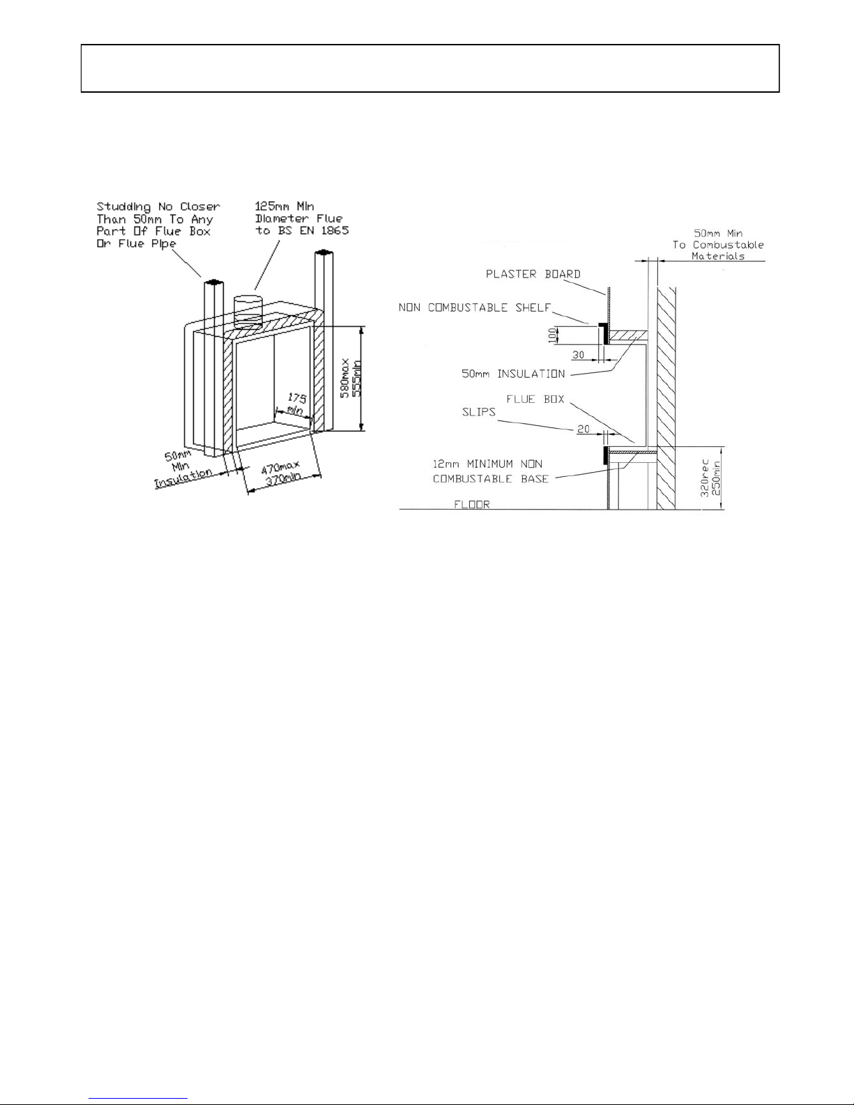
14.1 - FALSE CHIMNEY BREAST CONSTRUCTION
There must be no combustible materials used inside the flue box.
14.2 – BS 715 FLUE BOX BUILT INTO A FALSE CHIMNEY BREAST WITH FIRE SURROUND OR HOLE IN THE
WALL INSTALLATION WITH REQUIREMENTS (See diagrams above).
A BS 715 Flue Box can be built into a false chimney breast and installed at floor level with a suitable Fire Surround.
or
The Fire can be Built-In part way up the wall to create a Hole in the Wall Installation, however it is essential to use marble, slate or
stone slips, fitted around the builders opening. The slips must have a temperature rating of 150ºC and be 20mm (min) thick by
100mm (min) wide.
In order to direct the flow of heated air away from the wall we recommend that a non combustible shelf (lip) is fitted above the top
slip, protruding 30mm – see diagram.
For Hole in the Wall fires it is recommended that a means, (tactile separator/shelf or guard) is provided to give abrupt warning to a
person moving inadvertently towards the fire.
a. A suitable BS715 Shallow Flue Box can be used with the minimum dimensions quoted above.
b. The base of the Flue Box must be level and square to the face of the fireplace opening.
c. The Flue Box must sit on Non Combustible Material of at least 12mm Thick.
d. The Flue Box can be placed against a Non Combustible wall at the rear, however if the wall is combustible it must be spaced
50mm from the wall.
e. When building a False Chimney Breast No Combustible materials must be closer than 50mm to the Flue Box.
f. No Combustible materials must be closer than 50mm to the Flue over its entire route through the Property.
g. The Flue Box must be Insulated on its top and sides with 50mm thick Non Combustible Fibreglass Insulation or Equivalent.
h. If plaster board is used in front of the flue box it must be sealed to the box with high temperature Silicone Sealant or an
equivalent flexible sealant.
i. If the Fire is to be fitted into a purpose made Fire Surround it must have a temperature rating of 150ºC.
j. For a Fire Surround the fire requires a non-combustible hearth of at least 12mm thick.
k. The surface of the hearth must stand at least 50mm above the floor and level with the fireplace opening.
l. The hearth must project at least 300mm in front of the fireplace opening and 150mm either side (700mm minimum hearth width).
m. The Surround must cater for a minimum flat surface around the Fireplace Opening allowing 625mm high by 530mm wide. This is
essential in order to achieve a good seal between the face of the surround and the sealing flanges of the fire.
n. The Fire Surround must be fully sealed to the Fireplace Opening to ensure a good flue seal.
o. In order to direct the flow of heated air away from the wall we recommend that a non combustible shelf (lip) is fitted above the
top slip, protruding 30mm – see diagram in Section 14.1 on previous page.
p. There must be a flat surface around the opening of sufficient area to enable the slips to be securely fitted. The slips should be
fitted to the wall in such a way that they form a seal to stop air from the room being drawn behind the slips into the False
Chimney Breast. We recommend a high temperature silicon sealant.
BS715 Flue Box Hole In The
Wall Construction
14. BS715 SHALLOW FLUE BOX WITH TWIN WALL 5” FLUE – FALSE CHIMNEY BREAST
CONSTRUCTION WITH FIRE SURROUND OR HOLE IN THE WALL APPLICATIONS
BS715 Shallow Flue Box Application
Page 15

15
q. The recommended height for the base of the Builders Opening is 320mm above floor level. The minimum height for the base of
the Builders Opening is 250mm above floor level.
r. The Fireplace Opening should have provision for a gas supply through the rear, see Section 11 Gas Supply.
s. The High Level and Thermatronic control systems are fitted with Electronic Equipment, which is sensitive to dampness and high
humidity so it is very important that any rendering/building work is allowed to thoroughly dry out before Installation.
! IMPORTANT NOTE ! Do not forget to take account of the difference in height of the base of the Flue Box when
mounting the box on the floor; it must be level with the Hearth.
14.3 - CLEARANCES TO COMBUSTIBLE MATERIALS AND SHELVES (Ref: Diagram on Previous Page)
The Requirement for Shelves for Hole in the Wall Installations is Detailed in the Above Section.
a. For Fire Surrounds a non combustible shelf can be fitted above the fire and should be positioned at least 95mm above the
builders opening. We recommend the depth of the shelf should be a maximum of 75mm as anything deeper will reduce
convection air and the efficiency of the fire. For deeper non-combustible shelves they must be raised a further 25mm for every
extra 25mm of depth.
b. For Fire Surrounds a 150mm combustible shelf can be fitted above the fire but must be positioned at least 195mm above the
builders opening. For deeper combustible shelves they must be raised a further 25mm for every extra 25mm of depth.
c. Any combustible sidewall must be at least 500mm from the inside of the builders/fireplace opening, however with a combustible
fire surround it can be 150mm from the inside of the builders/fireplace opening provided it does not protrude more than 150mm
and this must be increased by 25mm for every extra 25mm of depth.
d. With all heating appliances, soft furnishings, decorations and wall coverings may discolour or scorch if placed too close.
e. No combustible material, e.g. curtains must be closer than 500mm to the builders opening.
f. Any combustible wall claddings (wall paper) must be cut back to a height of 750mm and 300 mm either side of the Fireplace
Opening.
g. Due to the heat output of The Hotbox H.E. it is not recommended to use blown vinyl wall covering around the fire.
NOW PROCEED TO SECTION 16 - FIXING THE FIRE.
Page 16
16
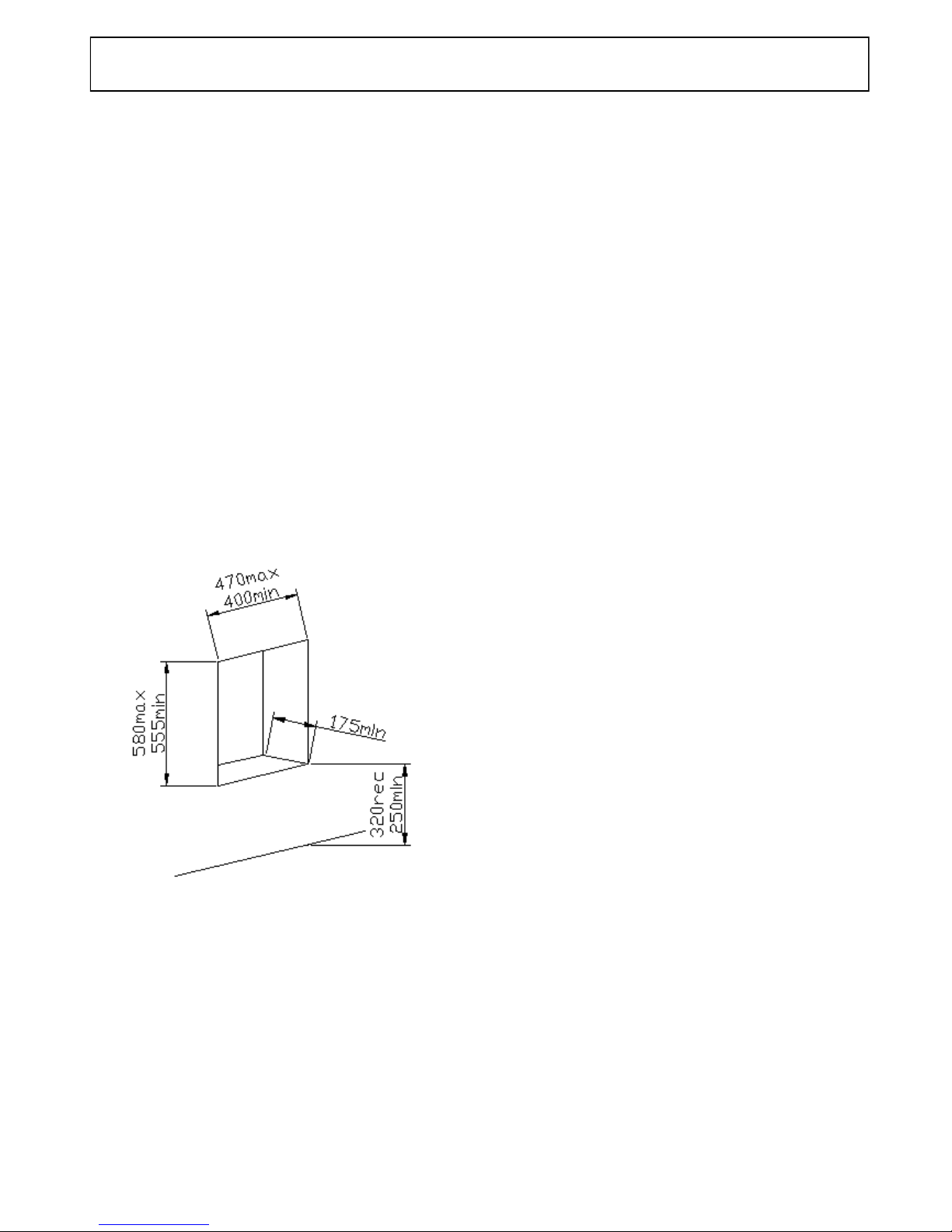
15.1 - SLIPS & WALL COVERINGS
It is essential to use marble, slate or stone slips, fitted around the builders opening. The slips must have a temperature rating of 150ºC
and be 20mm (min) thick and typically form a border round the opening of 100mm. In order to direct the flow of heated air away from
the wall we recommend that a non combustible shelf (lip) is fitted above the top slip, protruding 30mm beyond the front face of the slip
– see diagram in Section 15.3 on the following page.
With any form of heating appliance convection air will rise up through the fire carrying particles of dust that will in time result in
varying degrees of wall staining. The non-combustible shelf is designed to minimise this by deflecting the airflow away from the wall.
However, over time some staining might occur and we therefore suggest not using patterned paper around the fire.
Due to the heat output of The Hotbox H.E. it is not recommended to use blown vinyl wall covering around the fire.
Where the Chimney Breast is made of Stone or Slate or other Suitable Non Combustible Material with NO wall coverings then Slips
are Not Required but the Dimensions of the Builders Opening must be as shown below and a Flat Surface of at least 65mm must be
provided around the opening for sealing.
For Hole in the Wall fires it is recommended that a means (tactile separator/shelf or guard) is provided to give abrupt warning to a person moving inadvertently towards the fire.
15.2 - HOLE IN THE WALL APPLICATION (USING MARBLE SLATE OR STONE SLIPS & SHELF)
IMPORTANT NOTE ! Dry lined walls – ensure that any air gaps between the back of the plasterboard and wall are
sealed around the builders opening or fireplace as this can affect flue pull and wall staining.
a. It is recommended that a qualified builder constructs the
builders opening.
b. It is recommended that a lintel is fitted above the builders
opening.
c. The builders opening must be constructed from
Non-combustible materials.
d. No c omb ust ibl e mater ials mu st be p resent in the builders
opening.
e. The base of the builders opening must be flat, level and
square to the wall and be at least 12mm thick.
f. The builders opening should have provision for a gas supply
through the rear, see Section 11 Gas Supply.
g. There must be a flat surface around the builders opening of
sufficient area to enable the slips to be securely fitted. The
slips should be fitted to the wall in such a way that they form
a seal to stop air from the room being drawn behind the slips
into the builders opening. We recommend a high
temperature silicon sealant.
h. The recommended height for the base of the Builders
Opening is 320mm above floor level. The minimum height
for the base of the Builders Opening is 250mm above floor
level.
i. High Level and Thermatronic controlled models are fitted with
Electronic Equipment, which are sensitive to dampness and
high humidity so it is very important that any rendering/building
work is allowed to thoroughly dry out before Installation.
15. HOLE IN THE WALL APPLICATIONS INTO CLASS 1 or LINED FLUE
BUILDERS OPENING
Builders Opening for Hole in the Wall
application (when using marble, slate or
stone slips)
Page 17
17
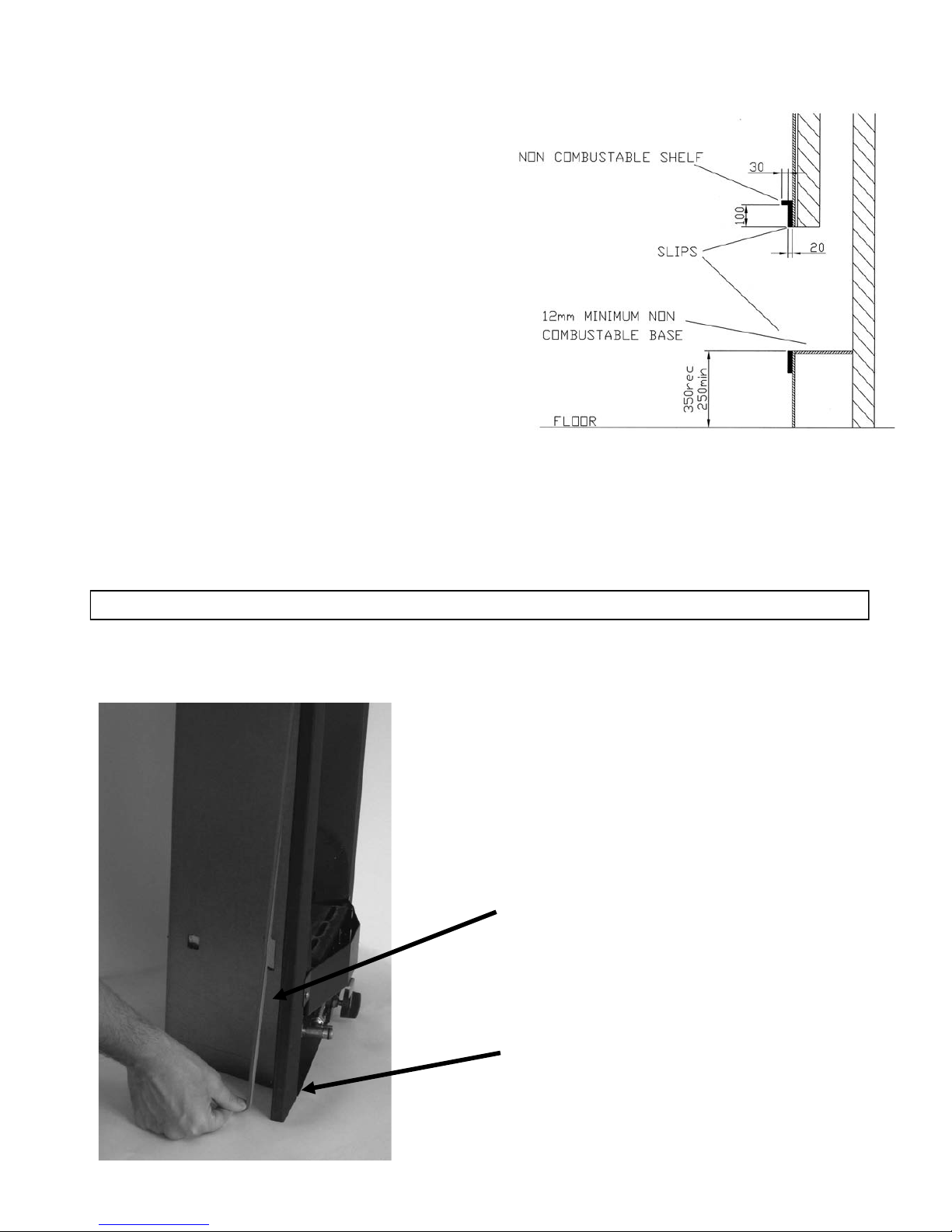
Hole in the Wall Installation into Class 1
or Lined Flue
15.3 - CLEARANCES TO COMBUSTIBLE MATERIALS
a. Any combustible sidewall must be at least 500mm from
the inside of the builders/fireplace opening.
b. With all heating appliances, soft furnishings, decorations
and wall coverings may discolour or scorch if placed too
close.
c. No combustible material, e.g. curtains must be closer than
500mm to the builders opening.
NOW PROCEED TO SECTION 16 - FIXING THE FIRE.
16.1 - FITTING THE SILICONE SEALING STRIP
16. FIXING THE FIRE
It is very important that a good seal is achieved between the back of
the Fire’s outer frame and the front of the fireplace back panel for
safety reasons and to achieve maximum efficiency. Take the self
adhesive silicone sealing strip from the fitting kit and neatly apply to
the back flanges of the Fire’s outer frame, cutting to the appropriate
lengths as required. To ensure there is a good seal between the
base of the fire and the bottom of the fireplace opening apply a
350mm length of self adhesive silicone sealing strip under the base
of the fire at the front edge.
Fit Silicone Sealing Strip to
back flanges of outer frame
Fit 350mm length of Silicone
Sealing Strip under the base of
the fire at the front edge
Page 18
18
16.2 - FITTING THE FIRE - references should be made to the drawings overleaf.
! IMPORTANT NOTE ! TAKE GREAT CARE WHEN WORKING INSIDE THE FIRE NOT TO MARK THE CERAMIC
LINING PANELS.
a. Using a Dust Sheet or equivalent protect the area around the Fire Installation.
b. Remove the Fire from the box and lay it on its back.
c. With the High Level and Thermatronic Control Systems remove the Control Heat Shield, which is secured with a single screw at the
base of the fire on the left side.
d. Now remove the Burner/Control Assembly by removing the 2 screws at the front of the fire taking care not to mark the liners.
Slide the Burner Assembly forward and if the fire is fitted with the High Level or Thermatronic Control it will also be necessary to
carefully slide out the Battery/Receiver Box and, in the case of the Thermatronic Control, carefully pull the Infrared Sensor off its
Velcro Pad.
e. Remove the Debris Plate at the back by removing the 4 screws allowing access through the Debris Opening for fitting the Gas
Supply.
f. There are fixing holes in the front flanges which can be used if there is sufficient strong material for fixing, however we
recommend the cable fixing system which is supplied to secure the unit into the fireplace. The cable fixing system will also pull the
unit tight back into the fireplace to make a good seal. This is very important to ensure efficient and safe operation of the fire.
g. There are a number of options for the Cable fixing system in different installation applications therefore please read the options
first before proceeding.
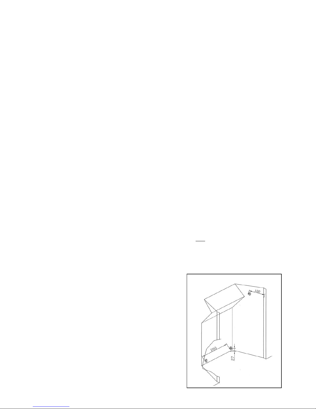
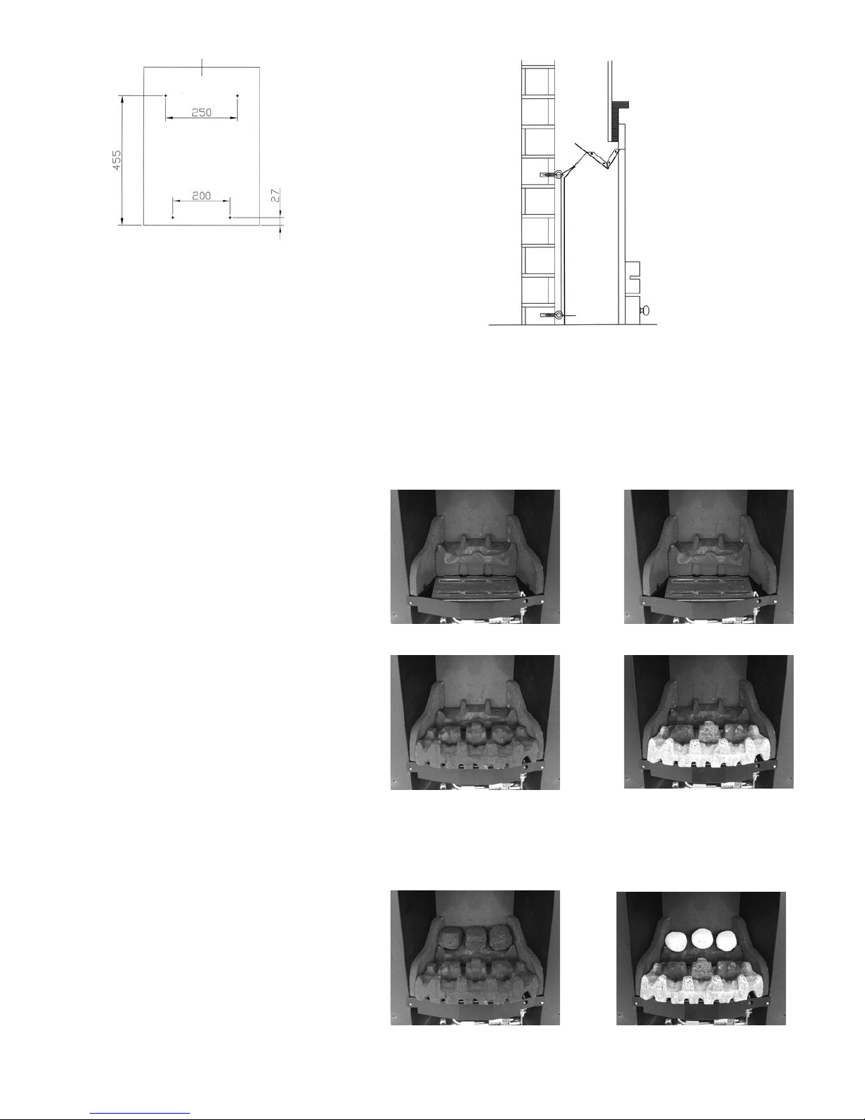
i. For Builders Openin g app lic atio ns an d with r eferen ce to the d iagr am overleaf use the 2 cables supplied;1 t o be used
each side of the unit. Working 27mm up from the base of the Builders Opening and at 200mm centres drill the lower holes and
then at 455mm up from the base but at 250mm centres drill the upper holes. Secure the 4 Eyebolts supplied with the Raw plugs
to the back of the fireplace.
ii. For Pre-cast Flue applications where the minimum depth is found it may be necessary to sink/rebate the Eye Bolts to ensure
the heads do not foul on the back of the fire.
iii. For Chairbrick application s and to preven t the cabl es fo uli ng o n th e Knee of th e Chairbrick the Upp er Eye Bol ts sh ould
be secured to the side walls of the Chairbrick. Positioned at same height as the standard option above but with the upper eye
bolts 100mm in from the front. See Diagrams below and on next page.
IMPORTANT: ENSURE THE MATERIAL THE EYEBOLT/RAWPL UG IS FIXED INTO IS SOLID AND SOUND. If the fixing is not
sound the Rawlplug/Eyebolt will be pulled out and the fire will not be sealed to the Fireplace Opening.
Note: With the minimum depth fireplace enclosure it may be necessary to sink the Eye Bolt Heads into the Brickwork.
h. With the Eye Bolts now in position there are 2 cable attachment tabs on the top of the main casing; 1 each side at the rear. Feed
a cable outward through each cable attachment point.
i. Feed the cables though the eyebolts on either side and then through the holes in the back of the fire near the base.
j. Slide the Fire part way into the fireplace (leaving it sticking out approximately 50mm) ensuring the gas supply pipe and isolation/
pressure test elbow clears through the Debris Opening in the rear of the Fire.
k. Slide the Fire fully home ensuring that the sealing strips on the rear of the Fire outer frame stay in position to make a seal against
the fireplace back panel. While sliding the unit into the fireplace opening pull on the excess cable.
l. Locate the supply pipe into the slot in the Debris Opening and replace the Debris Plate.
m. The Cable Fix Adjuster and Lock Screw can now be fitted onto the cable and tightened up to tension the fire back into the fireplace.
The fire should be secure and not liable to movement.
Surplus fixing cable MUST NOT be cut off and must be tucked back through the central hole in the Back of the Fire.
This is particularly important with the Electronic Control Systems to keep the cables away from any electronics.
n. If any of the silicone sealing strips are not compressed and/or if there are gaps they must be filled with a suitable sealant,
ideally high temperature silicone or fireclay. Refit the Burner/Controls Assembly with the 2 screws and with the High Level and
Thermatronic Control System refit the Battery/Receiver Box at the left hand side, and then, for the Thermatronic, secure the
Infrared Sensor onto the Velcro Pad. Then refit the Heat Shield above the Battery/Receiver Box and secure with the screw
removed earlier.
Important: Ens ure t he Red Bulb on t he Thermatronic Infrar ed Sensor i s fac ing Forw ard.
Important: Ens ure t he Heat Shield has b een fi tted with the High Level and Thermatro nic Control Sys tems.
o. Connect the isolation/pressure test elbow to the control valve and with it
fully open check the joint for gas soundness.
p. Check that all gas connections are sound. The appliance has been factory
tested; however the connections may have been
disturbed in transit or storage.
! TIP ! Ensure the Red Bulb on the Infrared Sensor is facing
Forward as this can prevent the Handset from working.
! IMPORTANT NOTE ! Always reseal the pressure test point
and check that it is gas tight. (This accounts for a lot of recalls.)
Cable Fixing Positions in a Chair-
brick
Page 19
19
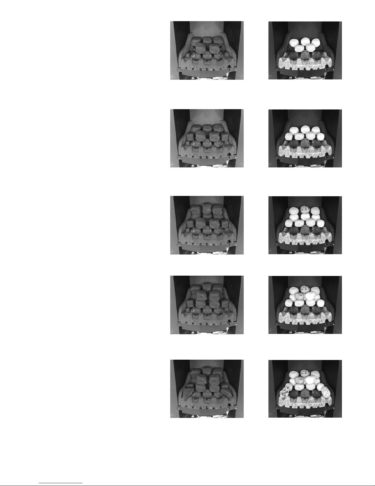
17. - ARRANGEMENT OF THE FUEL EFFECT (COALS or PEBBLES as Ordered).
Remove all the Fuel Effect parts, you will see there are different sizes and shapes of either Coals or Pebbles with 2
different Matrixes, the Front (in 2 halves) and Rear Matrix. Refer to the Coals or Pebbles diagrams.
! TIP ! Take care not to damage liner panels.
a. Fit the Rear Matrix
You may notice small white marks on
the Matrix. This is part of the production
process.
b. Fit the 2 parts that form the Front Matrix
You may notice small white marks on
the Matrix. This is part of the production
process.
! TIP ! When fitting the Coals/Pebbles leave gaps between as this helps achieve the best effect.
! TIP ! Pebbles only The Long Pebbles are marked Nos.3-7 for identification and have different textures and colours.
All the Large Pebbles are Marked No. 1 and all the Small Pebbles are marked No.2. Both Large and
Small Pebbles have different textures and colours
c. For Coals Layout
Fit 3 Large Coals at the Rear of the Fire.
For Pebbles Layout
Choosing different colours and textures fit
any 3 Large Pebbles at the rear of the Fire.
Hole Positions in back of
Fireplace Opening
Side View of Cable
Fixing System
Page 20
20
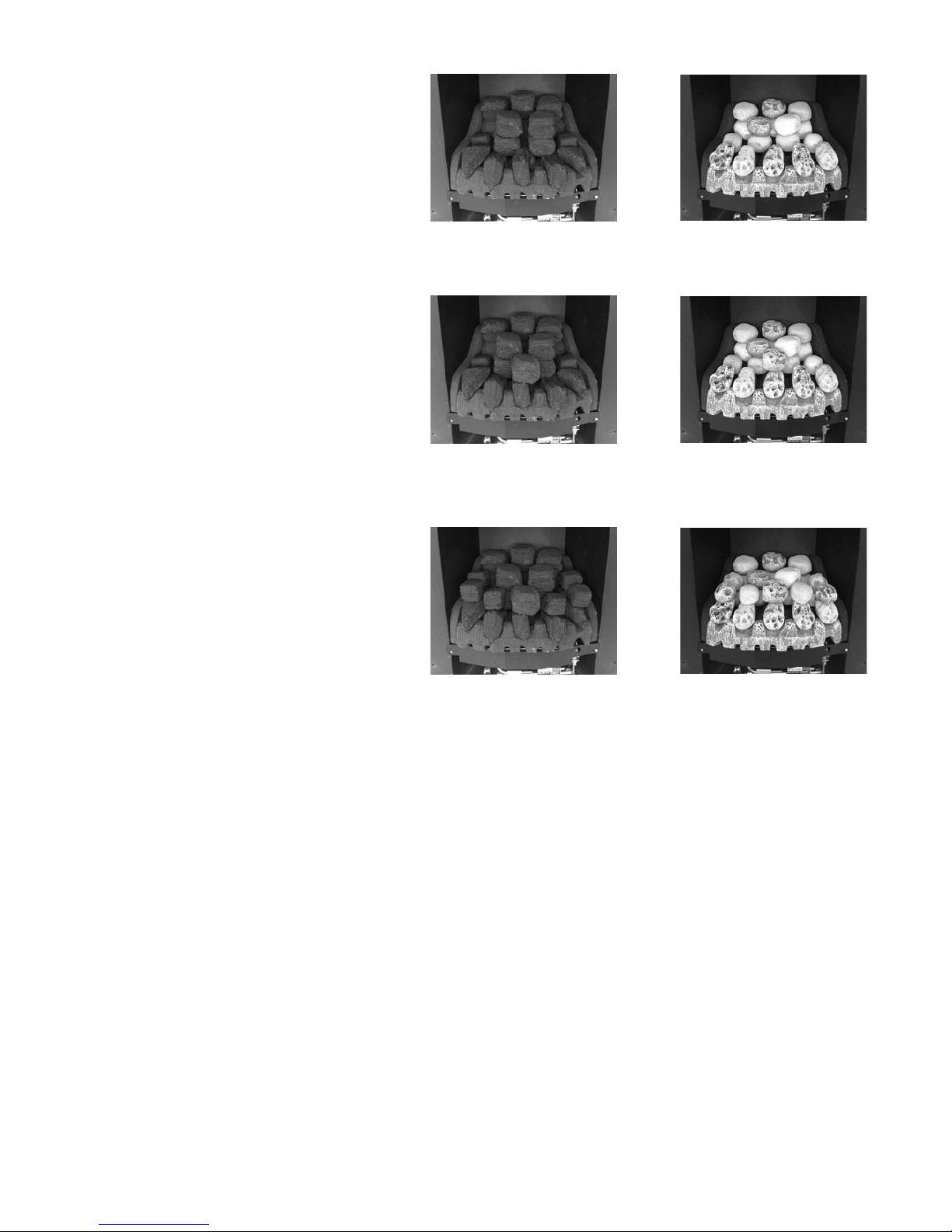
d. For Coals Layout
Fit 2 Large Coals at the Centre-Rear of the Fire.
For Pebbles Layout
Choosing different colours and textures fit
2 Large Pebbles at the Centre-Rear of the Fire.
e. For Coals Layout
Fit 2 Small ‘C’ Coals, 1 to the far left
and 1 to the far right of those fitted in d.
For Pebbles Layout
Fit 2 Small Pebbles, 1 to the far left
and 1 to the far right of those fitted in d
f. For Coals Layout
Fit 3 further Large Coals on top of the
3 large Rear Coals.
Note: The c entr e coal to b e edg e on and pu shed
up against the fireback to make it the highest
coal .
For Pebbles Layout
Choosing different colours and textures fit
3 further Large Pebbles on top of the 3 Large
Rear Pebbles.
g. For Coals Layout
Fit 2 further Large Coals on top of the
2 Large Coals.
For Pebbles Layout
Choosing different colours and textures fit
2 further Large Pebbles on top of the 2 Large
Pebbles.
h. For Coals Layout
Fit 2 Triangular Coals in the Front Left
and Right Corners of the Matrix.
For Pebbles Layout
Fit 2 Long Pebbles No.3 & No.7 in the Front Left
and Right Corners.
Page 21
21
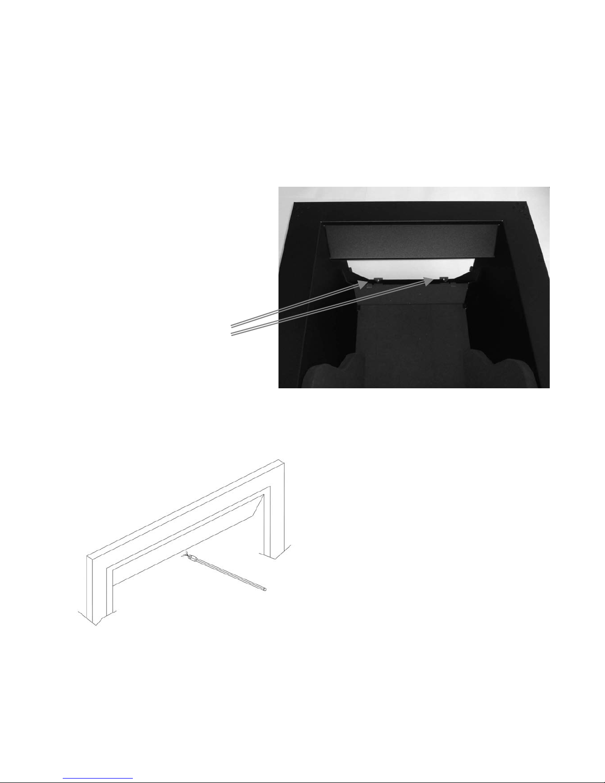
i. For Coals Layout
Fit 3 Triangular Coals along the Front of
the Matrix.
For Pebbles Layout
Fit 3 Long Pebbles Nos. 4, 5 & 6 along the Front
of the Matrix, with their narrow ends inward.
Note: Place t he Central Tr iang le Coal/Pebble
slightly forward to cover the joint in the Front
Matrix
j. For Coals Layout
Fit 1 Large Coals in the Centre of the
Fuel Bed.
For Pebbles Layout
Fit 1 Large Pebble in the Centre of the
Fuel Bed.
k. For Coals Layout.
Fit 6 Small ‘C’ Coals. Fit 1 either side of the Large
Coal on top of the Triangular Coals and sit the
remainder, 2 either side and behind the Small
‘C’ Coals just placed.
For Pebble Layout.
Fit 6 Small Pebbles. Fit 1 either side of the Large
Pebble on the top of the Long Pebble and sit the
remainder 2 either side and behind the Small
Pebbles just placed.
You may now wish to exchange the different
pebbles to achieve a better balance of
textures and colours.
l. Once the fire is first lit it may be necessary to adjust some of the Coals/Pebbles to improve the effect.
m. When first lit the flames will be quite tall and yellow; this is quite normal as production process materials are burnt off.
Page 22
22
18. - TESTING, COMMISSIONING & USE
! IMPORTANT NOTE ! During its first period of use any protective coatings and oils will burn out of the fire and it is wise
to ventilate the room for the first hour; also advise the customer that this may persist for the first
few days until the fire is fully burnt-in.
18.1 - LIGHTING THE FIRE
a. Reference to Section 2 in the Users Instructions ’Lighting & Controlling the Fire’ will show how to light and operate the fire.
b. Check that the supply pressure to the fire is at the pressures required, 20mbar Natural Gas G20 or 37mbar Propane G31 when
set at high.
! IMPORTANT NOTE ! Ensure that the pressure test point used is sealed and gas tight.
18.2 - TESTING FOR SPILLAGE
a. A restrictor is supplied with the fire for flues
that have an effective height greater than
3 meters. The restrictor must not be fitted
to Pre-cast Flue applications. The r estrict or
is fitted over the outlet duct on the inside of
the fire with the 2 # No.8 x 10mm pointed self
tapping screws provided, see photo on the
right
b. Once the fire is operational the installer must check for spillage. Close all doors and windows. Carry out the lighting procedure
and turn the fire to high. Allow to warm up for 5 minutes and then using a lit smoke match, joss stick or similar, place centrally just
under the inner canopy as shown below. The majority of the smoke must be drawn under the Fire Canopy. Some small whiffs of
smoke may be expelled and this is quite normal. Be careful not to introduce too much smoke (i.e. by using a pellet). A smoke match
tube can be used to make holding of the match easier. See following diagram.
c. Repeat the test with doors and windows to the premises/room both open and closed, and with any extractor fans in the same
room or adjacent rooms running at high. The fire should continue to clear its combustion products. Also operate any other flued
appliance in the same or neighbouring rooms and ensure they continue to function satisfactorily as multiple flues can work
against one another.
d. If spillage is detected during this procedure, remove the restrictor if fitted and repeat the tests.
e. If spillage is detected and no restrictor is fitted, let the fire operate for a further 10 minutes and re-check.
f. If the fire continues to spill, it could indicate a faulty flue or lack of ventilation. If the problem cannot be rectified immediately,
disconnect the fire, affix a label and advise the customer not to use it until the problem has been resolved.
g. It is an offence to use or allow the use of a dangerous appliance.
Restrictor fixing holes
Page 23

23
18.3 - FITTING THE OUTER TRIM
a. The Outer Trim is held in place with 4 strong Magnets, one at each corner, ensure they are in place.
With Profile Frames the Magnets must be on the metal corner plates.
b. To fit simply centralize the Trim and fit it onto the Fire. Note : If the Trim is not positioned centrally it may not be held correctly at
each corner, however it can be slid from side to side to ensure it is located correctly.
NOTE for Trim Variants: Various Trim/Frame Options are available some have integral Frets and others are supplied with
Separate Cast Frets. In all cases the Outer Frame is held as detailed above.
18.4 - FIREGUARDS
a. A fireguard is not supplied with the appliance however it is recommended that a fireguard conforming to BS 7977 is fitted if the
fire is to be used in the presence of young children, the elderly, the infirm and pets.
b. For Hole in the Wall fires it is recomm ended that a means , (tactile s eparator/s helf or guard) is provid ed to giv e abru pt
warning to a person moving inadvertently towards the fire.
19 - BRIEFING THE CUSTOMER
a. The installer should brief the customer on the Operation of the Control System fitted, (specifically the position for viewing the
pilot for lighting, when applicable); operation of the Coal-Coke System (if applicable) and all aspects of the User Instructions.
b. The instructions should be handed to the customer for their safe keeping and future servicing.
c. For Customers who have purchased either of the 2 or 3 Button High Level Control explain and demonstrate that the batteries
should be replaced with good quality batteries annually as the side switch may stop working part way through a season.
d. For Customers who have purchased the Thermatronic Control explain and demonstrate that the batteries in the receiver and
Handset should be replaced with good quality ones annually as the fire may stop working part way through the season.
e. The customer should be briefed on the need for regular servicing; this will normally be once a year.
f. Advise the customer that, apart from batteries for the High Level and Thermatronic Systems, there are no user replaceable parts
in the fire but for servicing and spares to contact the local Nu-Flame Stockist.
20 - SERVICING
The Matrix in the fire is a Moulded Ceramic Fibre component incorporating Silicone Binders and you may notice that it develops
cracks during operation. This is natural shrinkage caused by exposure to high temperatures and is quite normal for the material and
will in no way affect the operation of the fire.
20.1 - GENERAL
Note: Servicing must be carried out by a registered installer.
a. The fire does not have to be removed for Servicing.
b. Check the operation and ignition of the fire before servicing.
c. Ensure the fire is cold before proceeding.
d. Lay a dust sheet on the floor before proceeding.
e. Carry out a gas soundness test before servicing.
f. Taking great care not to mark the liners, remove the Ceramic Coals or Pebbles and the Front and Rear Matrixes. (The presence
of white marks and/or surface cracking/crazing on the matrixes is quite normal.)
g. Pull off the Outer Trim/Frame, (Locate the 4 magnets), & turn off the gas supply to the fire at the isolation/pressure test elbow.
h. If any parts need replacement, use only genuine parts supplied by Nu-Flame Ltd. Some components may look similar to those
used in other gas fire, but these are not necessarily the same due to performance variations and must not be used.
This applies particularly to the ODS Pilot, Gas Control System and Ceramics.
i. Disconnect the gas pipe to the control.
! TIP ! Being Magnetic The 4 Trim Magnets can be easily misplaced,. Locate them immediately.
20.2 - ANNUAL SERVICING
Carry out the operations in 20.1 General before proceeding
! IMPORTANT NOTE ! TAKE GREAT CARE WHEN WORKING INSIDE THE FIRE NOT TO MARK THE CERAMIC
LINING PANELS.
a. Referring to the Section 17, ‘Arrangement of the Fuel Effect’ and working in reverse order, remove the Coals or Pebbles and the
Front and Rear Matrixes. (The presence of white marks and/or surface cracking/crazing on the matrixes is quite normal.)
b. With the High Level and Thermatronic Control Systems remove the Control Heat Shield, which is secured with a single screw at
the base of the fire on the left side.
c. Now remove the Burner/Control Assembly by removing the 2 screws at the front of the fire taking care not to mark the liners.
Slide the Burner Assembly forward and if the fire is fitted with the High Level or Thermatronic Control it will also be necessary to
carefully slide out the Battery/Receiver Box and, in the case of the Thermatronic Control, carefully pull the Infrared Sensor off its
Velcro Pad. This will now allow access to all gas carrying parts for maintenance checks, fault finding and or replacement.
Take care when removing the Burner - DO NOT lift it out holding the Burner Top
d. Remove the Debris Plate by removing the 4 screws allowing access through the Debris Opening and clear away any Debris.
e. Brush clean the burner and pilot area of dust or debris; check that the aeration hole in the pilot is clear of dust, fluff, lint.
f. Refit in reverse order; brushing the coals/pebbles clean of any soot, checking gas soundness, ignition and spillage as detailed in
the relevant sections.
ALWAYS CONDUCT A GAS SOUNDNESS AND SPILLAGE CHECK AFTER SERVICING.
ALWAYS RESEAL THE PRESSURE TEST POINT AND CHECK THAT IT IS GAS TIGHT. (Thi s acc oun ts f or a l ot o f recalls.)
ALWAYS CHECK THAT THE CONTROL SYSTEM IS WORKING CORRECTLY. (This acc oun ts f or a l ot o f rec alls .)
Page 24

24
21 - FAULT FINDING GUIDE, SYMPTOMS AND POSSIBLE CAUSES
Important : In i nst ances where it i s in dic atin g that the main con tro l syst em needs changing, (specific ally the 3 B utt on Hi gh
Level or Thermatronic Control Systems), you should investigate returning the whole Burner Control Assembly to Nu-Flame for rectification as this could be the least cost option.
a. Prior to any Servicing ensure that you have carried out the procedures in Section 20.1 General (Servicing).
b. Check the supply pressure at the isolation elbow.
c. Important : Wi th t he Hig h Level an d Thermatronic Systems always ch ange t he bat teries before c arryin g out any Fau lt
Finding.
21.1 - RESETTING THE ELECTRONIC CONTROL (Applies to Thermatronic RF System Only)
Full Reset - If a n ew handset is o btai ned the control s ystem will need to learn th e hand set’ s un ique code via a Full Reset.
Also, if the fire is not working and the Basic Reset (described on page 6) has not worked a Full Reset can be carried out:
a. Remove the Ash Pan Cover and locate the electronic Receiver Box.
b. Locate the Reset Hole on the side of the Receiver and using a pen press and hold in the Reset button until you hear two beeps.
c. The first beep is short and the second beep is long. After the second beep release the Reset Button.
d. Now on the Handset, within the next 20 seconds press and hold the Small Flame Button until you hear two additional short
beeps confirming the code is set in the Receiver.
e. If you hear one long beep the Code as not been set so repeat the procedure.
f. If the Handset still does not work check the wiring and or replace the Receiver and Handset .
21.2 - NO SPARK IGNITION
a. Replace the batteries in the Receiver and Handset (The 3 Button High Level Switch as Receiver Batteries only).
b. Check there is no dust/debris shorting out the electrode or blocking gas from the pilot.
c. Check the condition of the Ignition lead and ensure it is connected to both the ignition electrode and /or High Level Control or
receiver. Check that the Ignition lead is not trapped and or shorting, replace if required. For the Manual System this will involve a
new control. For the High Level Control an the Thermatronic System a separate ignition lead is available.
d. Check that gas is flowing from the pilot during the ignition sequence. Clean or Replace as required.
e. For the 3 Button High Level Control & Thermatronic Radio Frequency versions only, listen to the control to hear if the pilot gas
solenoid is opening. Change the Receiver and High Level Switch or the Handset (which ever applies) at the same time and/or
gas control. Refer to Diagram for Cable connections in Section 22.
21.3 - PILOT GOES OUT AFTER FIRST LIGHTING
a. Check there is no debris blocking the flame to the thermocouple.
b. Check the thermocouple is tightly connected to the control.
c. Change the pilot assembly as a new thermocouple may be required.
d. With the Manual System or 2 Button High Level Control change the Controls.
e. For the 3 Button High Level Control & Thermatronic Radio Frequency versions only, listen to the control to hear if the pilot gas
solenoid is opening. Change the Receiver and High Level Switch or the Handset (which ever applies) at the same time and/or
gas control. Refer to Diagram for Cable connections in Section 22.
f. Also see Section 21.4
21.4 - PILOT LIGHTS BUT MAIN BURNER DOES NOT LIGHT
a. With All Control Systems listen to hear if gas is flowing into the main burner.
b. Check there is no dust or debris blocking the flame from the pilot to the main burner.
c. With t he 2 Bu tto n Hig h Level Control ch eck t hat b oth Control Knobs are in the on po sit ion , ful ly tur ned anti clockwis e.
Also check ‘e’ before determining the action required.
d. With the 3 Button High Level & Thermatronic System check if the main control knob on the control is turning to the high setting
and listen to hear if the valve is opening. If not change the Handset & Switch (which ever applies) and at the same time the gas
control.
For removal of the 3 Button Switch refer to ‘f’ and also refer to the Diagram for Cable connections in Section 22.
Also check ‘g’ (below) before considering replacing any parts. You should also consider the Important note in 21.1.
e. With the 2 Button High Level Control it is possible for the Main Burner to light when first lit after lighting the Pilot but then the
Push Buttons do not operate the control. Operate the bottom button and listen to see if the Control Knob turns. If it does not then
change the batteries, if still a problem change the Switch Assembly as detailed in ‘f’.
f. For removal/replacement of the 2 & 3 Button Switches first remove the 2 screws retaining the Switch Shield, remove the 2
screws retaining the Switch Assembly. Disconnect the push on wire connections at the control. Remove the switch and wires
and replace with a new component in reverse order.
g. All Control Systems have a Pressure Test Point to allow the Burner Pressure to be checked to confirm if gas is flowing from the
control. On the Manual Control it is visible at the front left of the control. On the High Level Controls it is on the left of the
control and on the Thermatronic it is at the front of the Control and is the left/rear Pressure Test Point.
h. Check if the main injector is blocked. Clean or Replace.
21.5 - PILOT FLAME SHORTENS, OR GOES OUT WHEN MAIN BURNER IS SELECTED
a. Monitor the supply pressure at the isolation elbow as the main burner lights. If pressure drops, check gas pipe sizing, quality of
pipe bending. Check for debris in the gas supply and or gas filter if fitted.
b. Check that another appliance is not affecting the gas supply pressure.
Page 25

25
21.6 - POOR FLAME PICTURE
a. Check the supply pressure is correct at the isolation elbow. If the pressure is low, check gas pipe sizing, quality of pipe bending.
Check for debris in the gas supply and or gas filter if fitted.
b. All Control Systems have a pressure point to allow the Burner Pressure to be checked. On the Manual Control it is visible at the
front left of the control. On High Level Control it is on the left of the control and on the Thermatronic it is at the front of the Control
and is the left/rear Pressure Test Point. You may wish to check ‘c’ first.
c. With the High Level Controls check the Buttons are operating correctly see Sections 21.3 & 21.4.
d. Check that another appliance is not affecting the gas supply pressure.
e. Check there is not a flue/ventilation problem – carry out a spillage test.
f. Check fuel bed layout as detailed in Section 17.
21.7 - FIRE OPERATES FOR A WHILE THEN GOES OUT
a. Check the supply pressure is correct at the isolation elbow with all other gas appliances working. If the pressure is low or
fluctuating up and down check gas pipe sizing, quality of pipe bending. Check for debris in the gas supply, pilot pipe and or gas
filter if fitted.
b. Carry out a spillage test from cold. Look for signs of Discoloured Walls or Trims as this may be an indication of a Downdraught
Problem.
c. Establish how long the fire stays alight then repeat the Spillage Test around this time.
d. For the Thermatronic System check that the Control is functioning correctly as detailed in Section 21.2 specifically the
Thermocouple Electrical Connections and Pilot Flame size.
Downdraught problems can be related to the condition of the flue, chimney termination or geographical location; so if a
Flue Problem is thought likely but no problem is found during the investigation isolate the fire and seek expert advice.
21.8 - THERMATRONIC RADIOA FREQUENCY CONTROL SYSTEM DOES NOT OPERATE
a. Check the Control is being operated correctly - see Section 2.2
b. Check for error messages and ch eck b atter ies - see Section 2.3
c. Reset the Mertik Maxitrol Logic Circuits - see Section 21.1
21.9 - HIGH LEVEL PUSH BUTTON CONTROLS DO NOT OPERATE
a. Chan ge the batteries then see if th e pus h bu tto ns now operate.
b. The Switch and Receiver/B atter y B ox shoul d be r eplac ed.
Important : In i nst ances where it i s in dic atin g that the main con tro l syst em needs changing, (specific ally the 3 B utt on Hi gh
Level or Thermatronic Control Systems), you should investigate returning the whole Burner Control Assembly to Nu-Flame for rectification as this could be the least cost option.
ALWAYS CONDUCT A GAS SOUNDNESS AND SPILLAGE CHECK AFTER SERVICING.
ALWAYS RESEAL THE PRESSURE TEST POINTS YOU HAVE USED AND CHECK THAT THEY ARE GAS TIGHT.
(This accounts for a lot of recalls.)
ALWAYS CHECK THAT THE CONTROL SYSTEM IS WORKING CORRECTLY. (This acc oun ts f or a l ot o f rec alls .)
Page 26
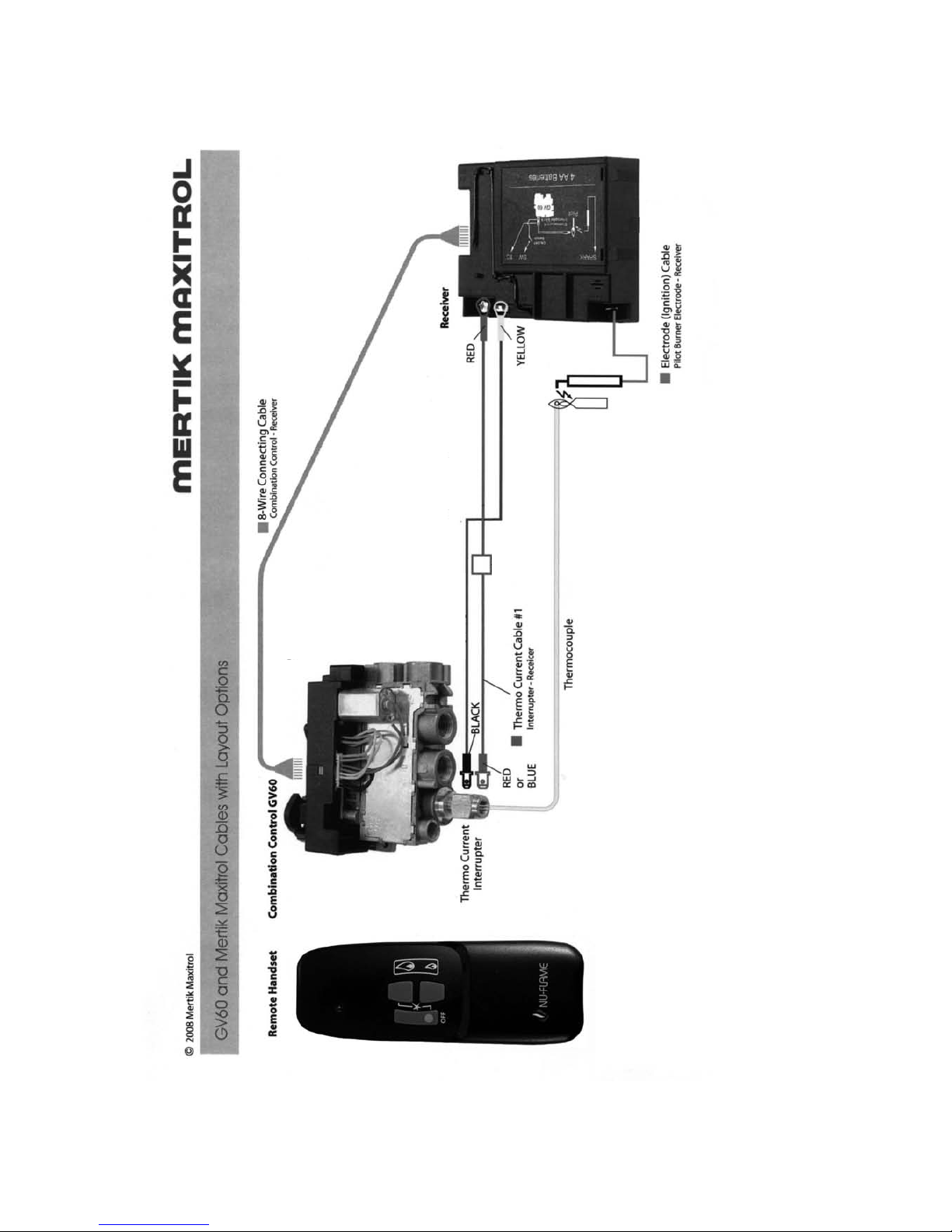
26
22. - DIAGRAM OF INFRARED CONTROL SYSTEM
Page 27

27
Telephone 020 8254 6802
Nu-Flame Warranty and Repair Procedure for The Hotbox H.E.
The Nu-Flame Hotbox H.E. is guaranteed for 1 year from the date of purchase. During that time our guarantee is to send
replacement parts for a fire that proves to have faulty components or workmanship. At our option we may decide to repair, or
replace, at no charge a fire that proves to have faulty components or workmanship.
Telephone Help Line. In the event o f a probl em with a fire t he fi rst cou rse o f act ion should be to telephone our tec hni cal
department on 020 8254 6802 during normal working hours 9 - 5.30 Monday - Friday (closed 1 - 1.30). If possible this should be
done before the installer leaves site as we may well be able to resolve the problem over the phone, and, in any event it will save
the installer a return visit to site. If we are not able to resolve the problem over the phone we will decide the most expedient way
of resolving the problem and this is likely to be to send replacement parts. It is possible that we will ask you to return the fire or
parts of the fire and if this is the case we will log your details and give you a return reference number.
Returning the Fire and parts thereof. After as sessment we mi ght con sider it best to return part of the appl ianc e, suc h as
the burner only, for testing. In this example the burner can then be thoroughly inspected and any signs of installation faults can be
reported back to you. After any repair work is carried out the flow rates can be checked and re-set if necessary in order to fully
comply with CE approval. Note: It is a condition of the warranty that you do not return any parts to us unless we request you to
do so. For example if we request that the burner only is returned and you send the entire appliance, the fuel bed and other items
could be damaged of lost during the return delivery to us. We will not be liable for any such breakages, or losses.
Under no circumstances should any attempt be made to repair the burner on site without our express knowledge and approval
during the warranty period.
This guarantee is given subject to the following provisions:
1. That the installation is carried out by a GAS SAFE registered installer (we may require their registration details).
2. That the appliance is installed and used in accordance with our Installation & User instructions.
3. That the gas supply pressure at the appliance is not more than 3mbar below the gas pressure stated on the data plate when
the appliance is running on high flame, with any other major gas appliances also running.
4. That the fireplace and flue system conform to relevant local codes, building regulations and British Standards.
5. This Guarantee is not transferable and relates to the original installation only.
6. The appliance has not been subject to misuse or accident or been modified or repaired by any person other than the
authorised employee or authorised representative of Nu-Flame Ltd.
7. The Record Data section on the front of the Installation & Servicing Instructions is to be completed on installation.
8. Nu-Flame Ltd accepts no liability for any consequential loss or damage arising from the use or failure of the product or any
information provided, including, but not limited to, economic or financial loss, damage to peripheral equipment or products,
loss of use, productivity or time.
9. That the serial no. data plate on the burner is intact.
This guarantee in no way reduces your statutory rights.
This guarantee supersedes any previously published guarantees.
Chargeable Repairs During And After The Warranty Period
If a repair is chargeable during the warranty period, due to installation faults we will inform you and where possible give you a
quote, or if this is not possible, a price guide before starting work. We cannot always give a firm cost until we commence the
repair as it is not always possible to tell which components have been damaged.
 Loading...