

Page 1

Page 1 of 4
Unit 4, Kimpton Trade & Business Centre
Minden Road, Sutton, Surrey, SM3 9PF
Tel: 020 8254 6802
Fitting & Operating Instructions For The Thermatronic Radio
Frequency Electronic Control System (Mertik Maxitrol)
General
Important Notes
Temperature Limits of Electronic Components
It absolutely necessary to ensure that the electronic control system components temperature do not rise above 60ºC.
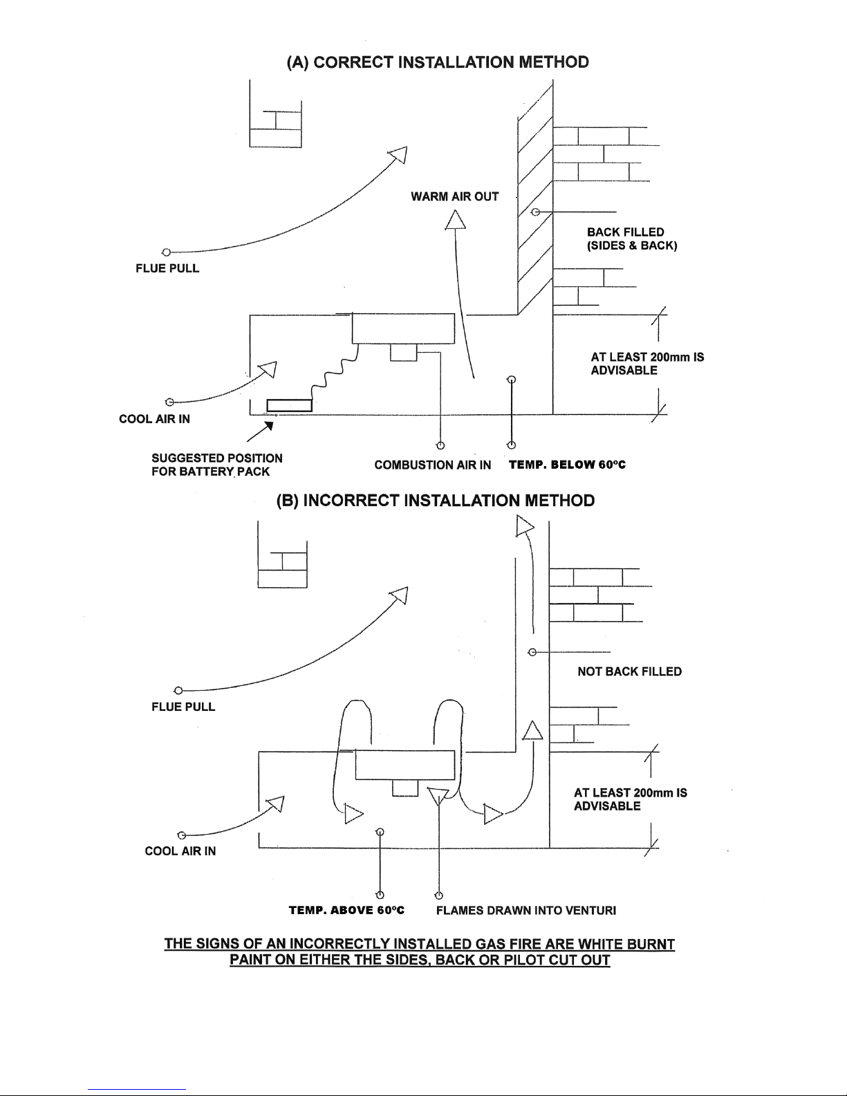
For Hole In The Wall installations (sunken burners) see the attached sketch showing our suggested installation arrangement. If you keep
to air inlet and outlet free areas of 100cm2 each and ensure that the void under the fire is properly backfilled (to avoid flue pull under the
burner) then, assuming a normal room temperature, the temperature of the electronic components should not rise too much above 30ºC.
This allows a big margin of safety.
It is also very important to ensure that the fire is not subjected to intermittent flue downdraught, which can blow flames/gas down to the
underside of the burner and cause overheating of the electronics.
Batteries
For Hole In The Wall installations (sunken burners) the fire is supplied with batteries in a separate box that has a long lead which plugs
into a socket on the standard electronics/battery box. This allows the batteries to be placed in an accessible place such as behind the air
inlet grille, as shown on the installation sketch.
If using the extended battery box ensure that any batteries are removed from the electronics box battery compartment. This battery box
is available as an optional extra for other installations, if required. Also available as an optional extra is a mains adaptor to be used
instead of batteries, which again has a long lead which plugs into the socket on the standard electronics/battery box. IMPORTANT –
BATTERIES MUST BE REMOVED BEFORE USING THE ADAPTOR.
Dampness
All electronic equipment is sensitive to dampness and high humidity. The Thermatronic equipment must be installed in a completely dry
place that does not access directly to outside air. If the fireplace has recently been rendered it must be allowed to completely dry out
before the electronic equipment is installed. It is possible that dampness has occurred during storage of the appliance, so as a
precaution we suggest placing the electronic box in a warm dry place for a while before installation.
Gas Supply
In common with all other gas appliances, dirt and debris in the gas system can block the valve and gas injectors on this appliance, and
faults caused by this are not covered by the guarantee. Pipework installation must comply with approved standards and practices. If in
doubt as to the cleanliness of site pipework, install a sediment trap, or filter as close to the appliance as possible.
Resetting the Mertik Maxitrol Logic Circuits (Radio Frequency Control)
BASIC RESET
It sometimes happens that (such as when the handset buttons are pressed out of sequence) the fire stops working because the logic
circuits get confused and need to be reset. To do this, simply remove the 4 x AA batteries from the Receiver Box (do not use metal tools
to do this), wait for 1 minute and then refit the batteries. Wait for another minute and then point the handset at the fire and press the
red/off button. Wait for another minute and then start the fire as normal. If the fire does not start repeat the resetting procedure. If the fire
still does not work a Full Reset can be tried (see below).
Note: If an extended battery box has been supplied, and the lead has been unclipped from the battery box, do not let the lead terminals
touch any metal parts, because voltage is still stored in the capacitors, which can cause a short circuit.
FULL RESET – TO BE USED IF A REPLACEMENT HANDSET IS OBTAINED
NOTE. On some burners such as the Fireboxx and “sunken” burners it is not possible for the user to access the Receiver Box
to carry out a Full Reset. If the user cannot access the reset button on the Receiver Box a Qualified Installation Engineer will
need to remove the burner to do so and this will involve disconnecting the burner from the gas supply.
If you obtain a new handset the control system will need to learn the handset’s unique code via a Full Reset. Also, if the fire is not
working and the Basic Reset (described above) has not worked a Full Reset can be carried out:
a. Replace the batteries in the Receiver and Handset.
b. Locate the Reset Hole on the side of the Receiver and using a pen press and hold in the Reset button until you hear two beeps.
The first beep is short and the second beep is long. After the second beep release the Reset Button.
c. Now on the Handset, within the next 20 seconds press the Small Flame Button until you hear two additional short beeps
confirming the code is set in the Receiver.
d. If you hear one long beep the Code as not been set so repeat the procedure.
e. If the fire still does not work, the problem lies elsewhere.
Note: If an extended battery box has been supplied, and the lead has been unclipped from the battery box, do not let the lead terminals
touch any metal parts, because voltage is still stored in the capacitors, which can cause a short circuit.
IMPORTANT NOTE
THIS APPLIANCE MUST BE INSTALLED & SERVICED BY A
PROPERLY QUALIFIED (IN ACCORDANCE WITH LOCAL &
NATIONAL CODES) GAS INSTALLATION ENGINEER.
THESE INSTRUCTIONS ARE FOR THE FIRE’S CONTROL SYSTEM
ONLY, AND MUST BE USED IN CONJUNCTION WITH THE
INSTALLATION INSTRUCTIONS FOR THE GAS FIRE.
Page 2
Page 2 of 4
General
The Thermatronic Control System is a battery operated gas fire control system that uses a microprocessor to provide
the working sequences needed by the fire, and when used with an oxypilot has all the safety features required by law
and CE approval.
Commands are accepted by the microprocessor when buttons are pressed. An audible beep means that the command
is received, and the push button should immediately be released.
Using The System
Control can only be achieved if the transmitter is pointed at the fire.
The red light will flash each time you press a button on the handset.
A - Ignition
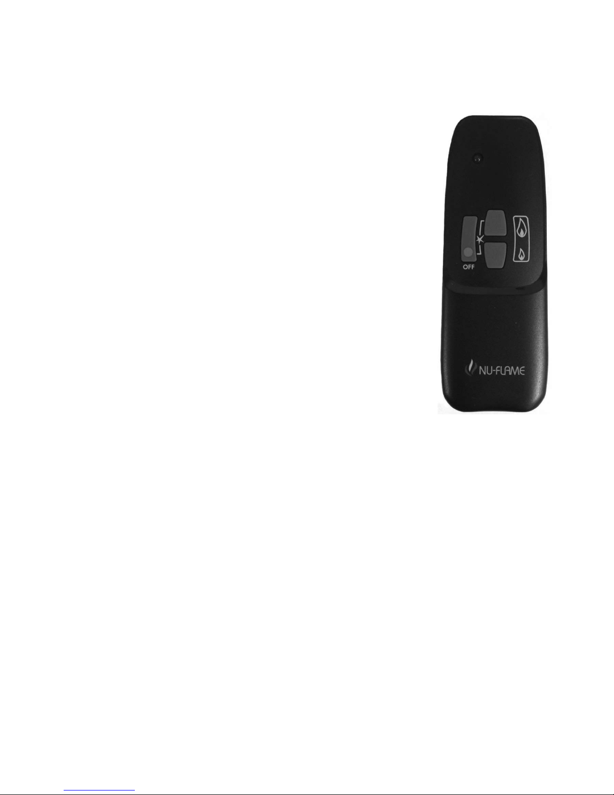
Simultaneously press and hold the red button and the right upper button (linked by line)
until a short acoustic signal confirms that the sequence has begun, then release the
buttons. Continuous audible signals confirm that ignition is in progress. When pilot
ignition is confirmed the motor will open the valve to maximum flame height – this takes
about 30 seconds.
B - Flame Height Adjustment
Press the small flame button until the flame height is at the desired position. If you try to
go beyond the preset low flame minimum height the main burner will turn off leaving the
pilot burner alight (this is the standby position). You will learn from experience the preset
low flame minimum height.
To relight the fire from the standby position, or to increase the flame height from low
flame, press and hold the large flame button until the desired flame height is achieved.
Please note that you can have the flame height anywhere between maximum and preset
low. For fine adjustment simply tap the up or down arrows.
C - To Switch Off
Press the red/off button on the handset.
D - General
Battery replacement is recommended at the beginning of each heating season, or when an acoustic error message
sounds during ignition.
Error Message – Long signals (0.8 second tone – 0.2 second break) during ignition – probable cause - batteries in
receiver are nearly discharged.
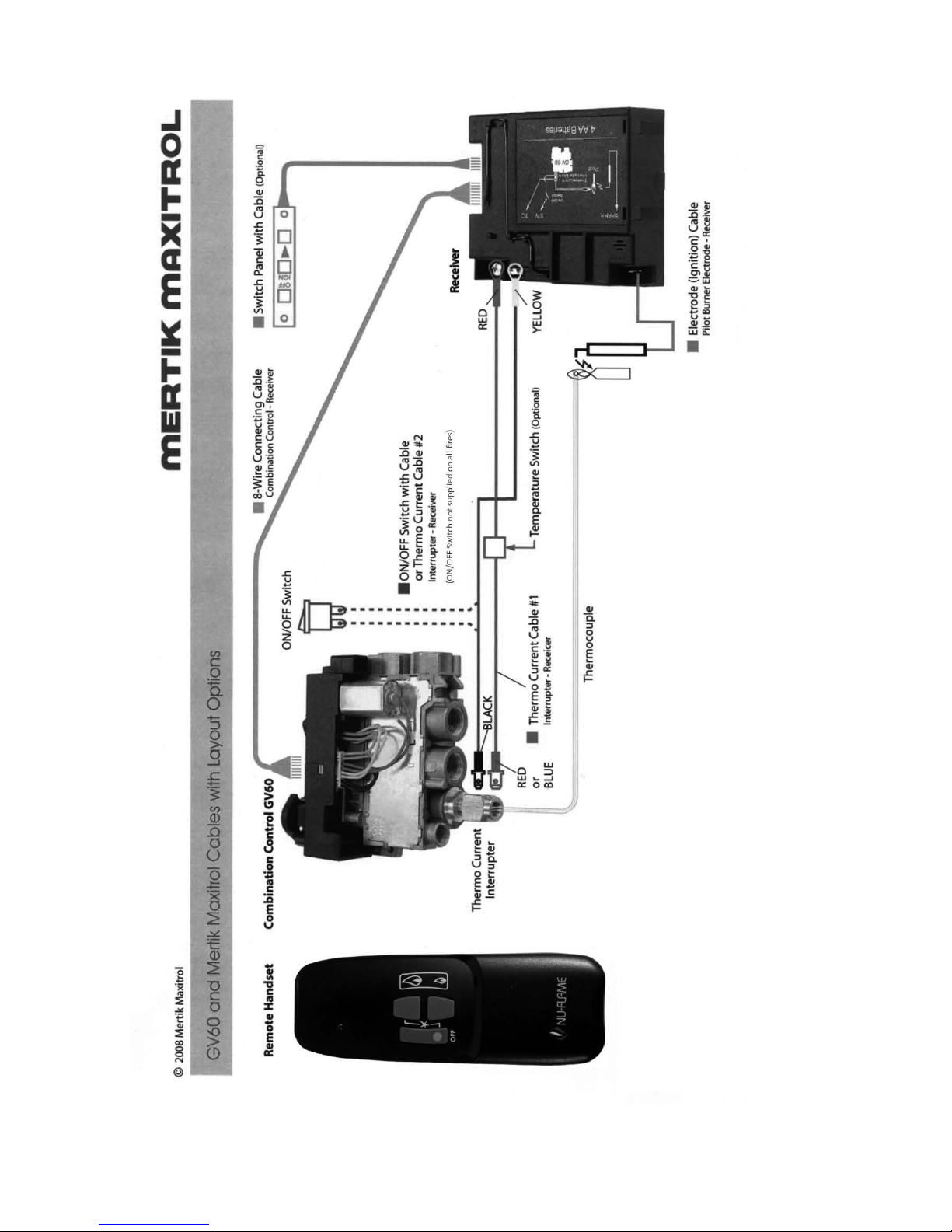
Error Message – 5 second continuous tone – probable cause – cable disconnected or on/off switch on valve is in off
position.
Batteries Receiver Box - 4 x AA good quality alkaline
Handset – 1 x PP3 good quality alkaline
Page 3
Page 3 of 4
Page 4
Page 4 of 4
 Loading...