

C
HANNEL
Portable Microwave Transmitter
M
ASTER
TX1
NUCOMM PUBLICATION: M01-0026-00A, REV 2.2
User Manual
Nucomm Inc.
101 Bilby Road
Hackettstown, NJ 07840
Tel: 908-852-3700 Fax: 908-813-0399
www.Nucomm.com

Revision 2.2
Warranty
Equipment manufactured by Nucomm, Inc. is warranted to meet all customer
specifications and to be free from defects in material and workmanship within a period
of two years from date of shipment from Nucomm. The company’s liability under this
warranty is limited to:
• Servicing or adjusting equipment.
• Replacement of defective parts.
Any equipment returned to the factory shall have the freight paid for by the buyer.
Equipment showing damage by misuse, abnormal conditions of operation, or attempts
to repair by other than authorized service personal shall be excluded from this warranty.
Nucomm, Inc. shall in no event be responsible for incidental injury or property damage.
Since Nucomm, Inc. has no control over conditions of use, no warranty is made or
implied as to suitability for the customer’s intended use, beyond such performance
specifications as are made part of the purchase order. There are no warranties
expressed or implied, except as stated herein. This limitation on warranties shall not be
modified by verbal representations.
Proprietary & Disclaimer Notice
All information and graphic images herein contained within this manual are considered
the sole property of Nucomm, Inc. and are issued in the strictest of confidence. This
material may not be reproduced, stored, copied, or converted in any form, nor shall it be
disclosed to others or used for manufacturing or any other purpose without the written
permission of an authorized representative of Nucomm, Inc.
Nucomm, Inc. has made every effort to ensure the accuracy of this material at the time
of printing. However, as the specifications, equipment, and this manual are subject to
change without notice, Nucomm, Inc. assumes no responsibility or liability whatsoever
for any errors or inaccuracies that may appear in this manual, or for any decisions
based on its use. This manual is supplied for informational purposes only and should
not be construed as a commitment by Nucomm, Inc.
© Copyrighted 2005, Nucomm, Inc., Hackettstown, New Jersey 08740
ii ChannelMaster TX1 Transmitter

Revision 2.2
Customer Service Information
Equipment Returns
Customer Service technicians at Nucomm are available to extend technical assistance to
customers installing or operating Nucomm equipment. They will also assist customers
with equipment troubleshooting. If this cannot be successfully accomplished by
telephone, the equipment may be returned to the factory for repair. Loaner equipment is
often available until Nucomm is able to ship repaired units.
Do not return any Nucomm product to the factory until you have received a return
authorization (RA) number and shipping instructions from Nucomm. When returning
equipment to Nucomm, please enclose a letter containing the following:
•
RA number.
•
Model number.
•
Serial number.
•
Frequency operating range (in the case of modules).
•
A detailed description of the problem.
•
Name of an engineer or technician we may contact in regards to this problem.
•
Include a “ship to” and “bill to” address.
Ship to:
Nucomm, Inc.
101 Bilby Road
Hackettstown, New Jersey 07840
For International orders
In the case of units being shipped from outside the United States, Nucomm recommends
the use of a courier such as Federal Express, UPS, etc, and that the goods be shipped
DOOR-TO-DOOR PRE-PAID. This will eliminate Customs costs, handling charges, and
delays. Enclose all the information above, plus a statement that the equipment was
manufactured in the United States (the latter is needed to expedite customs processing).
Nucomm evaluates all returned units free of charge, and then confers with customers on
corrective action.
Telephone Consultation
Should there be a need for emergency telephone consultation, please have your model
number and serial number available for the Customer Service representative. Nucomm
Customer Service representatives are available to deal with all technical questions or
difficulties.
ChannelMaster TX1 Transmitter iii

Revision 2.2
Replacement Modules
Troubleshooting to the component level is often not cost-effective and frequently
impossible. Often the practical method of effecting field repairs is to substitute known
good spare modules for suspect units. Nucomm maintains an inventory of replacement
modules for its standard line of products.
Field Repair
Nucomm products are designed with easy access to components to facilitate service.
When troubleshooting, the user is cautioned to read all module descriptions in this
manual. Some Nucomm modules cannot be serviced in the field. Warnings are included
in the circuit descriptions and on certain modules themselves, however; the lack of a
warning cannot be construed as a statement of safety. To prevent the voiding of the
Nucomm warranty that protects the equipment, please contact Nucomm before servicing
or making any repairs.
Shipping Damage
Equipment shipped FOB Nucomm, Inc.; shall become the property of buyer upon delivery
to and receipt from carrier. Any damage in shipment should be handled by the buyer
directly with the carrier. Immediately request the carrier’s inspection upon evidence of
damage in shipment.
Do not return any Nucomm product to the factory until a return authorization (RA) number
has been given, along with shipping instructions, as discussed previously.
Contact Information
Nucomm Inc.
101 Bilby Road
Hackettstown, NJ 07840
Tel: 908-852-3700 Fax: 908-813-0399
www.Nucomm.com
During Nucomm business hours, 8:30am – 5:30pm EST (-5:00 GMT):
US: ...................................................................................... (908) 852-3700
International:......................................................................... 001 - 1 - (908) 852-3700
24-Hour Hotline:
US: ....................................................................................... (888) 531-3892
International:......................................................................... 001 - 1 - (888) 531-3892
iv ChannelMaster TX1 Transmitter

Revision 2.2
CAUTION!
RISK OF ELECTRICAL SHOCK. DO NOT REMOVE COVERS.
• Do not remove any covers.
• Refer servicing to qualified technicians only.
• Disconnect all power before servicing.
• Read and perform all instructions carefully. Failure to follow suggested
instructions and guidelines may void all warranties.
!!""#$%#
&'()*'+
)'+.
FCC STATEMENT
ChannelMaster TX1 Transmitter v

Revision 2.2
TABLE OF CONTENTS
1.
DESCRIPTION ......................................................................................................................................1-1
2.
FEATURES............................................................................................................................................2-1
2.1 Configuration......................................................................................................................................2-1
2.2 Physical Description...........................................................................................................................2-2
2.3 Options ...............................................................................................................................................2-2
2.4 Accessories........................................................................................................................................2-2
3.
SPECIFICATIONS & FREQUENCY PLANS........................................................................................3-1
3.1 Frequency Plans (USA).....................................................................................................................3-4
4.
INSTALLATION .....................................................................................................................................4-1
4.1 Unpacking and Inspection .................................................................................................................4-1
4.2 Pre-Installation Checkout...................................................................................................................4-1
4.3 Mechanical Installation.......................................................................................................................4-1
4.4 Electrical Installation ..........................................................................................................................4-1
5.
OPERATION..........................................................................................................................................5-1
5.1 Power Up............................................................................................................................................5-1
5.1.1 Changing Characters .................................................................................................................5-1
5.2 Button Operation................................................................................................................................5-2
5.2.1 Changing Operating Frequency.................................................................................................5-3
5.3 Presets................................................................................................................................................5-3
5.4 Status Indicators (9)...........................................................................................................................5-6
5.5 Main Menu Selections........................................................................................................................5-6
5.6 Data Rate ...........................................................................................................................................5-9
5.7 Nextel BAS Relocation Settings ......................................................................................................5-16
5.7.1 Audio Sub-Carrier Frequency..................................................................................................5-16
5.7.2 Channel Bandwidth and Band Plan.........................................................................................5-17
5.7.3 Switchover to “Post-Nextel” Settings .......................................................................................5-17
LIST OF TABLES
Table 3-1 ChannelMaster TX1 Specifications..................................................................................................3-1
Table 3-2: Frequency Plan (US), 2GHz 17MHz...............................................................................................3-4
Table 3-3: Frequency Plan (US), 2GHz 12MHz...............................................................................................3-5
Table 3-4: Frequency Plan (US), 7GHz ...........................................................................................................3-6
Table 3-5: Frequency Plan (US), 12GHz.........................................................................................................3-7
Table 3-6: Frequency Plan (US), 13GHz.........................................................................................................3-8
Table 5-1ChannelMaster 8 MHz B/W Data Rates...........................................................................................5-9
Table 5-2 ChannelMaster 7 MHz B/W Data Rates........................................................................................5-10
Table 5-3 ChannelMaster 6 MHz B/W Data Rates .....................................................................................5-10
LIST OF FIGURES
Figure 2-1 ChannelMaster TX1 Block Diagram...............................................................................................2-3
Figure 4-1 ChannelMaster TX1 Front Panel....................................................................................................4-2
Figure 4-2 ChannelMaster TX1 Rear Panel.....................................................................................................4-2
Figure 4-3 RS 232 Connector...........................................................................................................................4-3
Figure 4-6 AC Line Cord Construction.............................................................................................................4-4
Figure 4-7 Audio Cable Construction ...............................................................................................................4-5
Figure 4-8 High Power Unit Detail...................................................................................................................4-6
Figure 5-1: ChannelMaster TX1 Front Panel Controls and Indicators...........................................................5-1
Figure 5-2 ChannelMaster Menu Tree...........................................................................................................5-18
vi ChannelMaster TX1 Transmitter

Revision 2.2
Document Revision
Date Modified Revision Modified by Modification Detail
May 25, 2005
October 10, 2005
January 18, 2006
April 3, 2006
November 6, 2006
0
1
2
2.1
2.2
M Hardy
M Hardy
M Hardy
M Hardy
R Risch /
M Hardy
Initial release
Removed reference to RS422 on
Page 4-3, Fig 4-3. Added
“Frequency Direct” info on 5-2.
Updated weights & specs.
Added BAS relocation. Updated
presets.
Misc. fixes; channel offsets
Addition of new features and Menu
functions, expanding of operation
section (text and graphics).
Nucomm makes every effort to ensure our documentation is accurate, and as
complete as possible.
In the event that you find any errors or omissions in our documentation,
please contact Nucomm Customer Service at (908) 852-3700, or via email
at service@nucomm.com.
ChannelMaster TX1 Transmitter vii

Revision 2.2
viii ChannelMaster TX1 Transmitter

Revision 2.2
1. DESCRIPTION
Nucomm’s ChannelMaster TX1 is a
Digital-Analog Portable Microwave
Transmitter. The tripod mounted
Microwave Transmitter System is
designed to operate in any specified
band in the 1.00 GHz to 15.5 GHz
frequency range. Each unit is field
programmable and configurable to meet
a wide range of customer requirements.
Standard features include fifteen presets
(the first five presets allow single button
operation), integrated dynamic color
bars, HD transport capability, field
programmable RF and Audio Subcarrier frequencies, RF power control,
local LCD display for control and
monitoring. Also, special menus have
been included to ease the BAS (US)
relocation process.
The ChannelMaster is fully integrated
with an Analog FM modulator, compliant
super-low delay MPEG 2 Encoder, and
Multimode Digital Modulator. Available
modulations include FM (NTSC / PAL),
COFDM, optional single carrier QAM,
and optional VSB. As additional digital
modulation formats become available,
the system can easily be software
updated. The ChannelMaster TX1 is
designed to be an extremely flexible
system, with limited circuit complexity.
The system video inputs include SDI,
ASI, Composite Video and External
70 MHz. The system comes standard
with two analog audios or one digital
AES. Optionally, the system can
support four analog audios or two digital
AES.
Other available options include: high
power amplifier, multi-band operation,
and standby power sourcing, as well as
other features and options. Contact
Nucomm for details.
This manual is written in general form to
cover all configurations and options for
the series within the 1.00 GHz to
15.5 GHz frequency range.
Description
1-1

Revision 2.2
Given the model number, the unit' configuration can be determined using the following:
AAAAA – CMTX1 – BBCC – X – YZ
Options
Emphasis Type
Specified Frequency Plan
Power Output
Model
Generalized Frequency Band Designator
Where:
AAAAA = mean frequency band center in GHz rounded to the closest GHz. This
number is then multiplied by 10. For multiple bands, each center frequency designation
is separated by a backslash "/".
BB = Used to identify the power output, per the following Power Output Designators:
Power Output is represented by Letters (A-Z; A=1, B=2, C=3, etc) for the analog power,
and Numbers (0-9) for the digital power. For example, a 5W Analog / 2W digital system
would be described with a power indicator of "E2". A Dual-Band system would have
two sets of power indicators, to show the power levels at both bands.
CC = Nucomm assigns a frequency chart number for each unique frequency channel
combination. Contact your Nucomm representative for further information.
X = Type Emphasis; 1 = NTSC and PAL M; 2 = PAL B/G
YZ = Miscellaneous options as listed below (append as many letters as needed)
M = FM only
M1 = COFDM only
M2 = FM / COFDM
M3 = FM / COFDM / DVBS
M4 = COFDM / DVBS
M5 = DVBS only
M6 = External 70MHz
Options that are not a standard part of the system, will be shown by shaded text as
shown here.
1-2
ChannelMaster TX1 Transmitter

Revision 2.2
2. FEATURES
2.1 Configuration
Nucomm’s ChannelMaster TX1 Series
Digital-Analog Portable Microwave
Transmitters are among the most
comprehensive portable radios in the
world. The ChannelMaster TX1
features are designed for both Analog
and Digital operation in portable links,
as well as helicopter and ENG/OB
applications. In the Digital mode, the
ChannelMaster accepts an external
digitally modulated signal with QPSK,
8PSK, 16QAM, 8VSB, COFDM, DVBS
and multi-level FSK. We also offer
internal FM, COFDM, VSB, and DVBS
(future).
The rugged ChannelMaster TX1
includes video and audio processing
boards, power supply, 70 MHz
modulator, power amplifier, upconverter, and low noise frequency
synthesizer enclosed in a weatherproof
enclosure that typically mounts on a
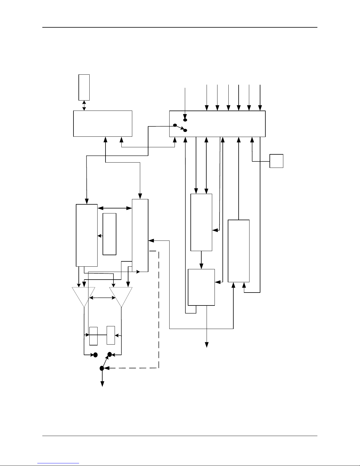
tripod. See Figure 1−1 for the system
block diagram.
The antenna (supplied separately) can
be either mounted directly to the
transmitter using one of our available
mounting adapters, or can be remotely
mounted to the transmitter and
connected via standard RF cables with
N-Type connectors. Many state-of-theart options are available on the
ChannelMaster, some not found on any
other portable Transmitters, leading to a
more cost-effective approach to portable
Microwave Systems.
The Nucomm ChannelMaster TX1
Series of transmitters are available in
single, dual, and multi-band models.
The ChannelMaster TX1 series radios
provide full coverage of the 2, 7, & 13
GHz US frequency bands and/or other
bands as required internationally, from
1 GHz to 15.5 GHz. The US frequency
bands are given in Table 1 through
Table 5. Band and channel selections
are made and clearly displayed via the
Front Panel LCD Interface.
Prime Power
All ChannelMaster TX1 transmitters
feature a built-in power supply, which
operates on power ranging from 90 to
240 VAC (40 to 60Hz), or +11 to
+32 VDC without the need for internal
jumpers or switch settings.
Audio Sub-carriers
Two (four optional) field programmable
synthesized audio sub-carriers feature
individual LINE/OFF/TONE source
selection, and automatic gain control
(AGC). The sub-carrier frequencies,
Mode, and additional gain are front
panel adjustable using the LCD
interface.
Standby Mode
In the Standby mode, the
ChannelMaster TX1 is powered on, but
the RF output is muted, enabling the
transmitter to be tuned safely without
radiating off-frequency emissions. The
ChannelMaster TX1 will remain in
Standby until on-frequency lock has
been obtained. Switching from Standby
to the Normal (operating) mode results
in instantaneous on-frequency
Features
2-1

Revision 2.2
transmission. If the synthesizer has not
attained a lock when the unit is switched
from Standby mode to Normal, the unit
will remain in Standby until on-frequency
lock has been obtained.
Signal Strength Indicators
Transmitted signal strength is indicated
on the LCD display by a digital readout.
The digital readout indicates the
transmitted signal level directly in watts.
(This function is intended as an
approximate reading of power only.)
Video Presence Detector
The Video Presence Remote Standby
mode enables the camera operator to
remotely turn on the color bars or put
the ChannelMaster TX1 in standby.
Internal Self-Test
Built-in diagnostic features include a
1 kHz audio test tone and a 761.5 kHz
(1.512 MHz for PAL) video deviation test
signal.
Other Standard Features:
• Digitally synthesized microwave
oscillator tuning
• Independent Gain Control for audio
inputs (Two audio sub-carriers
standard, four optional)
• RS232/RS485 Remote
• Power Adjustments
• Analog/Digital Operation
• Field Programmable RF and ASC
settings
2.2 Physical Description
The ChannelMaster TX1 measures 7.5
inches (19.05 cm) wide by 5.0 inches
(12.7 cm) high by 13.25 inches (33.65
cm) deep. It features a robust housing
design to withstand rough handling in
the field. The case is weather-resistant,
and all connectors are weatherproofed.
2.3 Options
• Test Pattern/ID Test Generator with:
o SMPTE RS-170A Color Bars
(EBU Pattern)
o A 16-character programmable ID
(can be placed in the Vertical
Interval and Gen-locked to the
incoming Video signal)
• Remote Control Software allowing
the ChannelMaster TX1 to be fully
monitored and controlled from an
IBM Compatible PC through a
RS232C/RS485 port.
• High Power Amplifier enabling
enhanced MER.
2.4 Accessories
ChannelMaster TX1 transmitters ship
with AC & DC power cords and manual.
With the addition of a modem, the
ChannelMaster can pass DS3/E3 or a
variety of other digital signals. The
ChannelMaster can accept PSK, QPSK,
8PSK, DVB-S, Multi-Level FSK,
16QAM, and COFDM signals directly
through the 70 MHz input connector with
no internal modifications.
Nucomm also offers a full line of
antennae and antenna mounting
equipment that seamlessly integrate
with the ChannelMaster series.
2-2
ChannelMaster TX1 Transmitter
Revision 2.2
2 AES
RS232
Ext 70 MHz Input
ASI In
Video In
4 Audio In
SDI In
AC/DC Input
Upper
LCD
Front
Panel
01
Front
Uproc
902-C111-
+12V, I2C
Panel
Lower
01
902-C122-
0
0
0
0
70MHz
I2c, RF_Pwr,
12V, 12V_Adj
12V, +5V
I2c, RF_Pwr_Out,
I2C
+12V
+12V
AC/DC
Converter
IF & RF UP
PA
YIG VCO
901-S089
902-I058/S088
Stdby-1
PA
902-C108-01
Channel Master Interface
36 MHz
Stdby-2
Det_1 & 2
36 to 70 MHz
Video, ASI, SDI Out, 4 Audio/AES
Modulator
902-M054-01
902-P051-05
I2c, 12V
Amplifier
902-M055-01
up-Converter
Power Supply
RF Output-1
Det
Det
RF Output-2
70MHz
+12V_PA, 12V_Adj
Output
70 MHz Monitor
RF Output
Figure 2-1 ChannelMaster TX1 Block Diagram
Features
2-3

Revision 2.2
2-4
ChannelMaster TX1 Transmitter

Revision 2.2
3. SPECIFICATIONS & FREQUENCY PLANS
Table 3-1 ChannelMaster TX1 Specifications
RF Performance:
Frequency Bands:.................................... bands from 1.9 GHz to 13.25 GHz available
(higher frequencies pending). Multi-band
models available. Please contact Nucomm for
specifics.
Tuning step size: ..................................... 250 kHz (US), 100 kHz (International)
70 MHz input:........................................... –10 dBm to 0 dBm (75 )
Frequency stability: ................................. ± 5 ppm (.0005%)
Power Output
Standby mode:
Standby: ............................................ No RF output
Normal: .............................................. HI power = Full power
.............................................. LOW power = 3.5 dB drop (typical)
Modulation Modes
Standard selectable:
Modulation 1: .......................................... COFDM: QPSK, 16QAM, 64 QAM
Code Rate: .......................................... 1/2, 2/3, 3/4, 5/6 and 7/8
Guard Interval: .................................... 1/32, 1/16, 1/8, 1/4,
Bandwidth: .......................................... 6 MHz, 7 MHz, and 8 MHz
Number of Audios:............................... Two audio standard; Four audio available
Data Rates: ......................................... to 32 Mbps
Modulation 2: Analog FM
Two field tunable sub-carriers; 4 available
Analog Modulation Deviation, selectable: ......................3 MHz/volt or 4 MHz/volt
Modulation 3: .......................................... VSB: 2VSB, 4VSB, 8VSB, 8VSBT
(Other modulation formats available with optional download.)
Video & Digital Input Performance:
Video: ...................................................... 525/625 lines NTSC/PAL field selectable
Pre-emphasis: ..................................... (Analog) NTSC/PAL-B,G or M LCD selectable
(CCIR 405)
Video Low-Pass-Filter LCD selectable: .....................3.9 MHz, 4.5 MHz, 4.75 MHz, and
5.6 MHz
Frequency Response: ......................... ± 0.25 dB (10 Hz to video filter selected)
Base-Band Response: ........................ ± 0.50 dB (10 Hz to 9 MHz)
Signal-to-noise ratio: ........................... 69 dB typical (65 dB minimum)
Differential Phase: .............................. ± 1.0 degrees
Differential Gain: ................................. ± 1.0 %
SDI Video: ............................................... SMPTE 259M Level C De-Embedded Audio
DVB-ASI: ................................................. Data Rates to 31.66845 Mbps
Input impedance: .................................... 75
Return loss:.............................................. –26 dB (10 Hz to 5 MHz)
Specifications
3-1

Revision 2.2
Table 3-1. ChannelMaster TX1 Specifications
(Continued)
Audio Performance:
Standard: ................................................. 2 line audio and 1 digital AES/EBU inputs
Available: ................................................. 4 line audio and 2 digital AES/EBU inputs
(audios can be analog, AES/EBU or SDI De-
embedded)
Analog Audio Mode
Sub-Carriers: ........................................... selectable and field tunable from front panel;
Tunable in 5 kHz steps 4.8 MHz to 9.0 MHz
Frequency Response:
30 Hz to 10 kHz: ................................ 0.5 dB
10 kHz to 15 kHz: .............................. 1.0 dB
Deviation: ................................................ 75 kHz peak at 1 kHz (100 kHz for PAL)
Pre-emphasis: ......................................... 75 µs & 50 µs LCD selectable
Digital Audio Mode:
Frequency Response:.............................. 30 Hz to 20 kHz: 0.5 dB
Digital & Analog Modes:
Line output:
US:...................................................... +8 dBm, 600 for 75 kHz peak deviation
International:....................................... +12 dBm, 600 for 100 kHz peak deviation
Signal-to-noise:
Line audio: ......................................... 65 dB
Harmonic distortion:
Line audio:.......................................... 0.5% maximum (typically 0.2%)
Remote Control:..................................... RS-232/RS-485; 9 Pin “D”
Power Requirements:............................ AC 90 to 240 VAC or +11 to +32 VDC.
Environmental:
Temperature range:
Full specification:................................ –30° to +60°C
Storage: ............................................. –40° to +80°C
Humidity: ................................................. 0 to 95% non-condensing
3-2
ChannelMaster TX1 Transmitter

Revision 2.2
Table 3-1. ChannelMaster TX1 Specifications
(Continued)
Physical Characteristics:
Size (Low Pwr Unit): ............................... 4.89" (12.42 cm) x 7.5" (19.05 cm) x 12.0"
(30.48 cm)
Size (Hi Pwr Unit): ................................... 5.2" (13.21 cm) x 7.5" (19.05 cm) x 12.0"
(30.48 cm)
Weight:
Single-Band (2 GHz), Low-Power:..... 15.25 lbs (6.86 kg)
Duale-Band (2/7 GHz), Low-Power: .. 16.50 lbs (7.43 kg)
Single-Band (2 GHz), High-Power:.... 15.75 lbs (7.09 kg)
Duale-Band (2/7 GHz), High-Power:.. 17.00 lbs (7.65 kg)
Connectors:
Video / SDI / DVB-ASI / 70MHz IF: ........ Type BNC-F
RF Output: ............................................... Type “N-F” RF Head
Audio: ...................................................... Multi-pin, Detoronics DT02H-14-15PN
(XLR break-out cable provided)
Power: ..................................................... Multi-pin MS Type, Detoronics DT02H-14-18PN
(XLR break-out cable provided)
Remote Control: ...................................... 9 Pin “D” Female
Case:
Ruggedized to withstand rough handling in the field with handles that protect controls
from damage. Case is weather-resistant and all connectors are weatherproofed.
Specifications
3-3

Revision 2.2
3.1 Frequency Plans (USA)
The standard US frequency plans apply to all units sold into markets covered by the FCC.
Frequency plans for all systems sold into non-US markets are individualized to meet
specific customer requirements and licensing restrictions, as specified at the time of
purchase.
CHANNEL / FREQUENCY PLAN - CHART NO: 326
2 GHz (17 MHz)
(Frequency Range 1,994 MHz – 2,497 MHz)
Channel Offset Receive Frequency MHz
1 –
1 0
1 +
2 –
2 0
2 +
3 –
3 0
3 +
4 –
4 0
4 +
5 –
5 0
5 +
6 –
6 0
6 +
7 –
7 0
7 +
8 –
8 0
8 +
9 –
9 0
9 +
10 –
10 0
10 +
1,994.75
1,999.00
2,003.75
2,012.25
2,016.50
2,020.75
2,029.25
2,033.50
2,037.75
2,046. 25
2,050.50
2,054.75
2,063.25
2,067.50
2,071.75
2,080.25
2,084.50
2,088.75
2,097.25
2,101.50
2,105.75
2,454.25
2,458.50
2,462.75
2,471.00
2,475.25
2,479.50
2,487.50
2,491.75
2,496.00
Table 3-2: Frequency Plan (US), 2GHz 17MHz
3-4
ChannelMaster TX1 Transmitter

Revision 2.2
CHANNEL / FREQUENCY PLAN - CHART NO: 326
2 GHz (12 MHz)
(Frequency Range 2,025 MHz – 2,496 MHz)
Channel Offset Receive Frequency MHz
1 –
1 0
1 +
2 –
2 0
2 +
3 –
3 0
3 +
4 –
4 0
4 +
5 –
5 0
5 +
6 –
6 0
6 +
7 –
7 0
7 +
8 –
8 0
8 +
9 –
9 0
9 +
10 –
10 0
10 +
2,028.50
2,031.50
2,034.50
2,040.50
2,043.50
2,046.50
2,052.50
2,055.50
2,058.50
2,064.50
2,067.50
2,070.50
2,076.50
2,079.50
2,082.50
2,088.50
2,091.50
2,094.50
2,100.50
2,103.50
2,106.50
2,454.25
2,458.50
2,462.75
2,471.00
2,475.25
2,479.50
2,487.50
2,491.75
2,496.00
Table 3-3: Frequency Plan (US), 2GHz 12MHz
Specifications
3-5

Revision 2.2
CHANNEL / FREQUENCY PLAN - CHART NO: 326
(Frequency Range 6,431 MHz – 7,119 MHz)
Channel Offset Receive Frequency MHz
1 –
1 0
1 +
2 –
2 0
2 +
3 –
3 0
3 +
4 –
4 0
4 +
5 –
5 0
5 +
6 –
6 0
6 +
7 –
7 0
7 +
8 –
8 0
8 +
9 –
9 0
9 +
10 –
10 0
10 +
11 –
11 0
11 +
12 –
12 0
12 +
13 –
13 0
13 +
14 –
14 0
14 +
6,881.25
6,887.50
6,893.75
6,906.25
6,912.50
6,918.75
6,931.25
6,937.50
6,943.75
6,956.25
6,962.50
6.993.75
6,981.25
6,987.50
6,993.75
7,006.25
7,012.50
7,018.75
7,031.25
7,037.50
7,043.75
7,056.25
7,062.50
7,068.75
7,081.25
7,087.50
7,093.75
7,106.25
7,112.50
7,118.75
6,431.25
6,437.50
6,443.75
6,456.25
6,462.50
6,468.75
6,481.25
6,487.50
6,493.75
6,506.25
6,512.50
6,518.75
3-6
ChannelMaster TX1 Transmitter
Table 3-4: Frequency Plan (US), 7GHz

Revision 2.2
CHANNEL / FREQUENCY PLAN - CHART NO: 10
(Frequency Range 12,706MHz - 12,950MHz)
Channel Offset Receive Frequency MHz
1 -
1 0
1 +
1 ++
2 -
2 0
2 +
2 ++
3 -
3 0
3 +
3 ++
4 -
4 0
4 +
4 ++
5 -
5 0
5 +
5 ++
6 -
6 0
6 +
6 ++
7 -
7 0
7 +
7 ++
8 -
8 0
8 +
8 ++
9 -
9 0
9 +
9 ++
10 10 0
10 +
10 ++
12,706.25
12,712.50
12,718.75
12,725.00
12,731.25
12,737.50
12,743.75
12,750.00
12,756.25
12,762.50
12,768.75
12,775.00
12,781.25
12,787.50
12,793.75
12,800.00
12,806.25
12,812.50
12,818.75
12,825.00
12,831.25
12,837.50
12,843.75
12,850.00
12,856.25
12,862.50
12,868.75
12,875.00
12,881.25
12,887.50
12,893.75
12,900.00
12,906.25
12,912.50
12,918.75
12,925.00
12,931.25
12,937.50
12,943.75
12,950.00
Specifications
Table 3-5: Frequency Plan (US), 12GHz
3-7

Revision 2.2
CHANNEL / FREQUENCY PAN - CHART NO: 10
(Frequency Range 12,976MHz - 13,250MHz)
Channel Offset Receive Frequency MHz
1 - 12,956.25
1 0 12,962.50
1 + 12,968.75
1 ++ 12,975.00
2 - 12,981.25
2 0 12,987.50
2 + 12,993.75
2 ++ 13,000.00
3 - 13,006.25
3 0 13,012.50
3 + 13,018.75
3 ++ 13,025.00
4 - 13,031.25
4 0 13,037.50
4 + 13,043.75
4 ++ 13,050.00
5 - 13,056.25
5 0 13,062.50
5 + 13,068.75
5 ++ 13,075.00
6 - 13,081.25
6 0 13,087.50
6 + 13,093.75
6 ++ 13,100.00
7 - 13,106.25
7 0 13,112.50
7 + 13,118.75
7 ++ 13,125.00
8 - 13,131.25
8 0 13,137.50
8 + 13,143.75
8 ++ 13,150.00
9 - 13,156.25
9 0 13,162.50
9 + 13,168.75
9 ++ 13,175.00
10 - 13,181.25
10 0 13,187.50
10 + 13,193.75
10 ++ 13,200.00
11 - 13,206.25
11 0 13,212.50
11 + 13,218.75
11 ++ 13,225.00
12 - 13,231.25
12 0 13,237.50
12 + 13,243.75
12 ++ 13,250.00
3-8
ChannelMaster TX1 Transmitter
Table 3-6: Frequency Plan (US), 13GHz

Revision 2.2
4. INSTALLATION
4.1 Unpacking and Inspection
Unpack and visually inspect the unit for
LCD, connectors, and surface area
damage. All claims should be filed with
the carrier. Save all shipping and
packing materials for possible re-use.
4.2 Pre-Installation Checkout
Connect the ChannelMaster RF output
through a 30 watt, 30 dB attenuator to a
spectrum analyzer. Verify the output
frequency and level correspond directly
to the transmitter front panel settings.
4.3 Mechanical Installation
The unit ships pre-assembled and
requires no mechanical installation other
than cabling. Optional accessories such
as Triax cable, tripod, direct mounting
antenna, or rack/vehicle mounting kits,
are shipped with necessary instructions.
4.4 Electrical Installation
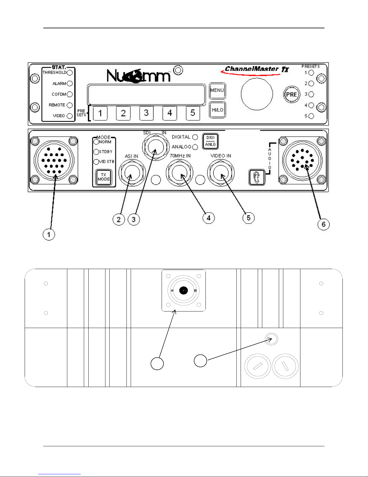
The unit front and back panels are
shown in Figure 4-1 and Figure 4-2.
Connector details are shown in Figures
4-3 to 4-5.
Power Connection (1)
The built-in power supply accepts 90 to
240 VAC (40 to 60 Hz) or +11 VDC to
+32 VDC without requiring any jumper
or switch settings. See Figure 4-5.
Nucomm ships a DC cable, and the
appropriate local AC line cord. Alternate
line cords are available upon request.
Optional "Standby" Power feature:
For power redundancy, the unit can be
configured to accept both AC AND DC.
ASI, SDI, Composite & 70MHz ports
All video inputs are made via 75 BNC
coaxial cables to the appropriate, clearly
marked, front panel port.
ASI (to 31.66845 Mbps) or SDI signals
are input via the ASI IN (2) or SDI IN (3)
ports. Composite or Baseband video is
input via VIDEO IN (4). 70 MHz is input
via the 70 MHz IN port (5). Select the
appropriate input type via the front panel
interface. See Section 5 for details.
Optionally, the unit can be fitted with an
ASI OUT port (not shown), for use as a
standalone ASI encoder.
AUDIO Inputs (6)
All audio inputs are made via this
connector. See Figure 4-4. The Digital
AES/EBU inputs are on Audios 1 & 3.
Only one Digital audio is available in the
standard “two audio” configuration.
RS232 connector (left side of unit)
This port is for control and monitoring
via RS232 or RS485. See Figure 4-3.
RF OUTPUT (7)
RF output is via a Type-N connector at
the rear of the unit. Directly connect a
suitable antenna, or a 50 , low-loss
coaxial cable (such as RG-214U)
between the RF Output and the antenna
connector.
POWER SWITCH and FUSES (8)
The unit has AC & DC fuses. The AC
fuse is 2.5 Amps (fast blow). The DC
fuse is 10 Amps (fast blow).
Installation
4-1
Revision 2.2
Figure 4-1 ChannelMaster TX1 Front Panel
7
8
ON
DCAC
Figure 4-2 ChannelMaster TX1 Rear Panel
4-2
ChannelMaster TX1 Transmitter

Revision 2.2
9
RS 232 (DB9
-F)
5
1
6
Pin # Function
1 N/C N/C
2 RX / IN RX/A
3 TX / OUT TX/A
4 N/C N/C
5 GND GND
6 N/C TX/B
7 N/C N/C
8 N/C RX/B
9 +11Volts +11Volts
RS232 RS485
Figure 4-3 RS 232 Connector
PIN-OUT DESCRIPTION
J +…….Analog1/AES1
H GND..Analog1/AES1
G -……..Analog1/AES1
M +…….Analog2
L GND..Analog2
K -……..Analog2
F +…….Analog3/AES2
E GND..Analog3/AES2
D -……..Analog3/AES2
C +…….Analog4
B GND..Analog4
A -…….Analog4
Nucomm P/N: 512-M2014-015
Detoronics P/N: DT02H-14-15PN
Mating Connector
Nucomm P/N 512-F3012-015
Mil-C-26482, Series 1
P/N: MS3116J-14-15S
Figure 4-4 Audio Connector (6)
PIN-OUT DESCRIPTION
C AC Neutral
E Chassis GND
G AC Line
H, S GND
P, U, B +DC IN
M RS232 TX / OUT
L RS232 RX / IN
Nucomm P/N: 512-M2001-000
Detoronics P/N: DT02H-14-18PN
Mating Connector
Nucomm P/N 512-F3001-000
Mil-C-26482, Series 1
P/N: MS3116F-14-1PS
Figure 4-5 Power Connector (1)
Installation
4-3

Revision 2.2
Figure 4-6 AC Line Cord Construction
4-4
ChannelMaster TX1 Transmitter

Revision 2.2
CM Transmitter Audio Cable
PIN-OUT DESCRIPTION
J +…….Analog1/AES1
H GND..Analog1/AES1
G -……..Analog1/AES1
M +…….Analog2
L GND..Analog2
K -……..Analog2
F +…….Analog3/AES2
E GND..Analog3/AES2
D -……..Analog3/AES2
C +…….Analog4
B GND..Analog4
A -…….Analog4
Figure 4-7 Audio Cable Construction
Installation
4-5
Revision 2.2
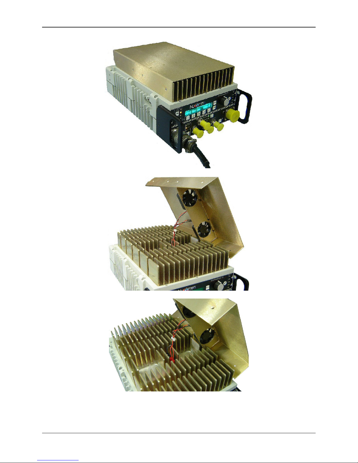
4-6
ChannelMaster TX1 Transmitter
Figure 4-8 High Power Unit Detail

Revision 2.2
5. OPERATION
Figure 5-1: ChannelMaster TX1 Front Panel Controls and Indicators
5.1 Power Up
Upon powering up the unit, you will see
three quick screens showing the
equipment type, the model number, and
the serial number. After that, the unit
will display the DEFAULT screen, which
will look similar to the following photo
(depending on your configuration).
Once this screen appears, options and
settings can then be changed and
initialized through the use of the front
panel "Quick-Keys" and pre-set buttons,
or via the menu system. The front panel
of the unit is depicted in Figure 5-1.
Menu navigation is via the rotary "Quick
Knob" switch (2) to the right of the LED
display. Turn the "Quick Knob"
clockwise or counter-clockwise to move
the cursor through the menus. By
pressing the "Quick Knob", you are able
to select, or activate, menu items. As
such, the "Quick Knob" may also be
referred to as the "Enter" button.
5.1.1 Changing Characters
1. Begin by rotating the “Quick
Knob” until the desired screen
item is hightlighted. Press Enter
to select the item.
2. The left-most character position of
the name will then be highlighted.
Rotate the “Quick-Knob” until the
desire alpha-numeric character
appears.
3. Press the “Quick-Knob” to save
the character.
4. Move the cursor to the second
character, rotating the “QuickKnob”.
5. Press the “Quick-Knob” to select
the character.
6. Rotate the “Quick-Knob” until the
desire alpha-numeric character
appears.
Operation
5-1

Revision 2.2
7. Again, Press the “Quick-Knob” to
save the character.
8. Repeat Steps 2 thru 7 until either
the desired name is assigned or
all character positions are filled.
On certain screens (as with system
settings), an arrow is used to show the
current setting, as in the following where
"SDI" is currently set:
Note the highlighted arrow at the
bottom left of the screen. This
highlighting is the "cursor", and indicates
an item that is ready to be selected.
Note: After one minute of inactivity the
display reverts to the DEFAULT screen,
and any un-activated selections are
discarded.
5.2 Button Operation
Set Modulation Mode (3)
The ChannelMaster TX1 modulation
mode is set to ANALOG or DIGITAL,
based on the Modulation Mode selected
on the front panel through the use of the
“DIGI_ANLG” Button.
Switching to Digital Mode
When digital modulation is selected,
the available input selections will be:
Composite - The signal is converted
to digital via the MPEG Encoder and
routed to the digital modulator.
SDI - The signal routes through the
MPEG Encoder and then to the digital
modulator.
External 70 MHz Digital - This input
bypasses the encoder and modulator,
and routes to the heterodyne upconverter.
ASI - Input bypasses the Encoder
and goes to the digital modulator.
(The ASI rate must be at or below the
maximum digital modulation rate.)
Pressing the “DIGI_ANLG” Button,
immediately switches the
ChannelMaster TX1 from the one mode
to the other (from Digital to Analog, or
from Analog to Digital Mode). This is
made apparent from the Input LED’s
(located next to the button) and a text
message displayed on the LCD.
5-2
ChannelMaster TX1 Transmitter
Switching to Analog Mode

Revision 2.2
When analog modulation is selected,
the available input selections will be:
Composite - The composite signal is
routed through the internal low pass
filter (bandwidth ± 4.0 MHz NTSC,
± 5.6 MHz PAL typical.) then sent to
the FM modulator.
SDI - Internal circuits convert SDI
inputs to Composite. The signal is
then processed as Composite.
External 70 MHz FM - This input
bypasses the modulator, and routes
to the heterodyne up-converter.
Set Power Level (4)
The user can toggle between HI or LOW
power by merely pressing the “HI/LO”
Button.
The LCD will then immediately display
the change at the bottom right corner.
Unit in Low Power Mode
5.2.1 Changing Operating
Frequency
1. Ensure that the Main Menu
screen is displayed on the LCD.
2. Rotate the “Quick-Knob” to
highlight the preset parameter to
be changed.
3. Press the “Quick-Knob” to enter
the selection.
4. Rotate the “Quick-Knob” to adjust
the value of the selection.
5. Press the “Quick-Knob” to enter
the changed value.
6. Rotate the "Quick Knob" until the
digit that needs to be changed is
highlighted.
7. Press "Enter".
8. Change the digit as needed.
9. Press "Enter".
10. Repeat until all digits are correct.
11. When all digits are correct, move
the cursor to the end of the
frequency where it says “GHz”.
12. Press "Enter".
When the operating frequency is
changed, the unit goes into standby
while the synthesizer re-tunes to the
new frequency. Transmission resumes
when the new frequency is reached.
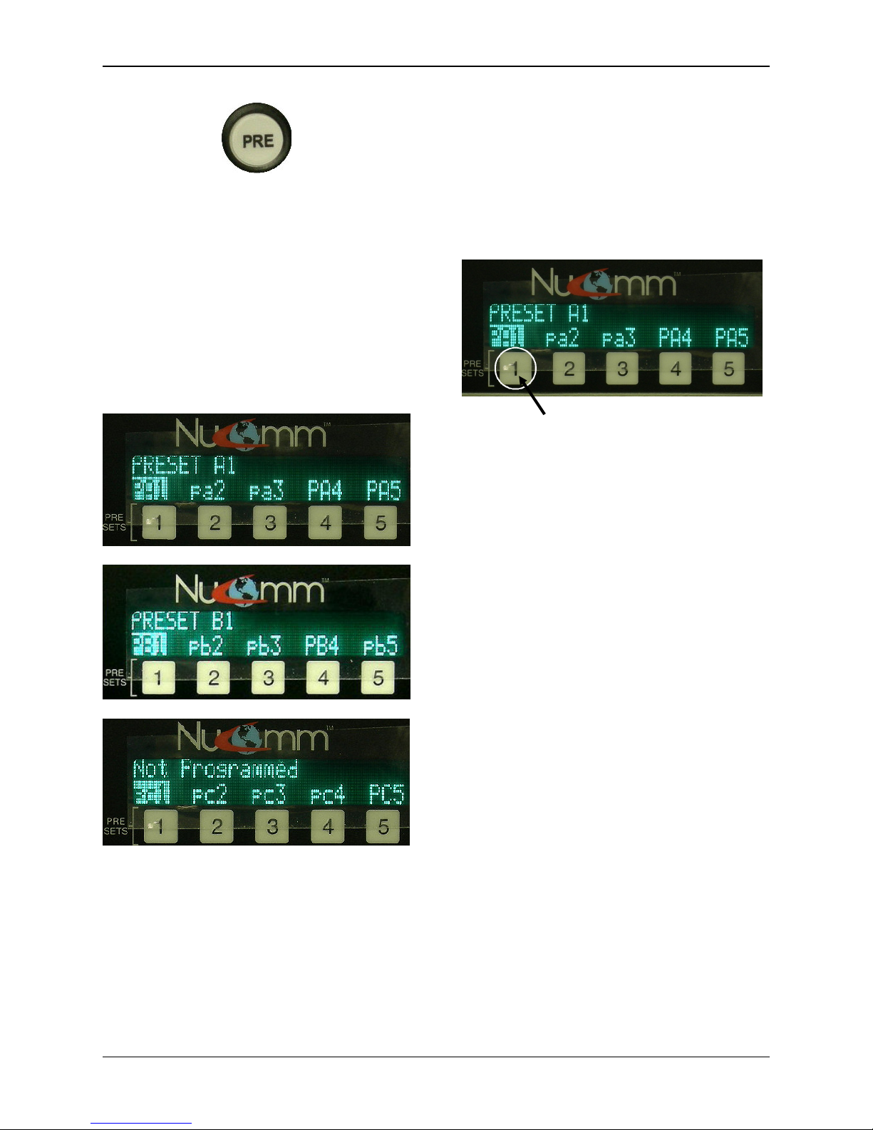
5.3 Presets
There are 15 Channel Presets. These
Presets are either changed or recalled
through the numbered “Preset” Buttons,
or through the “PRE” Button.
The numbered Preset Buttons are pa1
through pa5, located just below the
LCD. These five numbered preset keys
are provided to rapidly store and recall
five custom configurations without
button operation.
Accessing the remaining presets
requires using the “PRE” Button.
Operation
5-3
Revision 2.2
To change these parameters, refer to
Section 5.2.1 or 5.5.
“PRE” Button
For Presets pa1 – pa5, simply press &
hold the numbered button just below the
As well as also bringing up the first group
of presets (pa1 – pa5), the other two sets
desired preset to save it.
of presets are only accessible through
the “PRE” (Preset) Button. Pressing the
“PRE” Button once brings up the presets
pa1 – pa5. Pressing the “PRE” Button
twice, brings up the presets pb1 – pb5.
Pressing the “PRE” Button three times,
brings up the presets pc1 – pc5.
Press & hold numbered button below
the desired preset to save it.
For Presets pb1 – pb5, & pc1 – pc5,
press the “PRE” Button the appropriate
amount of times to bring up the set
containing the desired preset. Rotate the
“Quick-Knob” until it highlights the
desired preset, and press & hold the
“Quick-Knob” to save it until the
confirmation message is displayed
(approximately 4 seconds).
When a preset is saved, all system
parameters are stored into memory with
the associated preset. These
parameters include:
• Modulation Parameters
• Input Type
These presets are set and saved in the
same way as the numbered “Preset”
Buttons.
Changing & Setting Preset
Parameters.
Before saving a preset, program the
• Power Mode
• Channel Number & Frequency
• Audio Settings
The ChannelMaster LCD indicates which
of the presets have been programmed as
well as those that have not been
programmed. All presets represented by
capital letters have been programmed.
radio with the desired parameters.
5-4
ChannelMaster TX1 Transmitter
Revision 2.2
All presets represented by lowercase
letters have not been programmed.
Example:
• PA1 - has been programmed.
• pa1 - has not been programed.
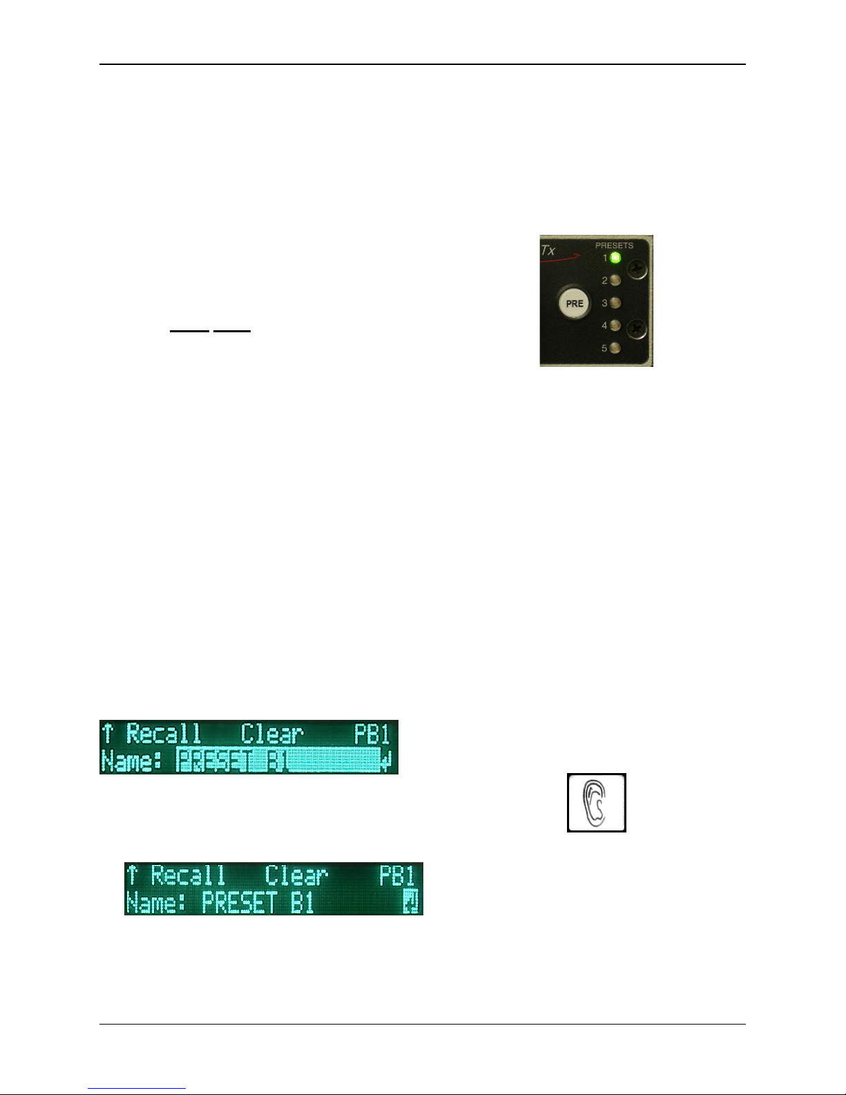
Changing & Setting Preset Name
Each preset can be given a name up to
16 characters long. The name can
consist of alpha-numeric characters only
(characters A – Z & 1 – 9). The preset,
however, must have the channel,
frequency, and band saved first before it
can be assigned a name.
To assign a name to a preset, perform
the following:
1. From any menu screen, press the
“PRE” Button the appropriate
amount of times to bring up the
set containing the desired preset.
2. Rotate the “Quick-Knob” to
highlight the preset to be assigned
a named.
3. Press the “Quick-Knob” to enter
the selection.
4. Rotate the “Quick-Knob” until the
name area is hightlighted.
5. Press the “Quick-Knob” to enter
the selection. (Refer to Section
5.1.1 for Changing Characters.)
Recalling A Preset
Briefly press the preset to recall settings.
When any of the first five Presets have
been recalled, the associated Preset
LED will illuminate.
Preset 1 recalled
NOTE: If the unit is enabled for Preset
Lock RF CHN, the frequency cannot be
changed by a preset and will remain the
current operating channel.
TX MODE (7)
The TX MODE key is used to select
from the following operating modes:
• NORMAL: Transmitter is active,
with or without a video (or
composite) input signal.
• STANDBY:Transmitter is in
STANDBY until switched to
another mode. Frequency
synthesizer is locked on
frequency.
Highlighted Name Area
6. When completed, move the cursor
over the arrow at the bottom-right.
7. Press the “Quick-Knob” to select
the arrow. The name has now
been saved.
Operation
• VID STB (Video Standby): Not
functional at this time.
AUDIO Quick Key (8)
The AUDIO quick key provides a
shortcut to the audio settings.
When modulating digitally, the system
will display the Encoder's audio settings
5-5

Revision 2.2
as if you had selected the following
menu items: Menu>Encoder>Audio.
(Refer to Section 5.5; Encoder Menu
Selections.)
When modulating in analog, the system
displays the FM audio settings, as if the
following items were selected: Menu>
Modulation> Parameters> FM> Audio.
(Refer to Section 5.5; FM.)
From the Upper Level Menu, the user
can select one of six sub-menus to
access. They are:
• Input Menu
• Modulation Settings Menu
• Encoder Settings Menu
• System Settings Menu
• Monitoring Menu
• Alarms (Current)
5.4 Status Indicators (9)
The following show the unit's status:
RF (Green): RF present at output port.
Color Bars: Color Bars are active.
Alarm (Red): Indicates an improper
setting or a module failure. The exact
reason for the alarm can be
determined from the Alarm section of
the Main Menu.
Remote: Unit is under remote control.
Video (Green): Indicates that video is
present.
5.5 Main Menu Selections
The user can customize the
ChannelMaster TX1 operation (rather
than using the factory defaults)
through the Main Menu. After
pressing the Main Menu Button, the
Main Menu Screen will appear.
Input Menu Selections
The Input Menu works in conjunction
with the DIGI_ANLG (Digital/Analog)
Button. Once the type of modulation is
chosen, the operator then uses the
Input Menu to manually select the
input source that is to be made active.
5-6
ChannelMaster TX1 Transmitter

Revision 2.2
As previously discussed in Section
5.2, the Digital inputs consist of:
• Composite
• SDI
• External 70 MHz
• ASI
As previously discussed in Section 5.2,
the Analog inputs consist of:
• Composite
• SDI
• External 70 MHz
Remember, only one input can be made
active at any time. Only the Input Menu
can select the active input, regardless of
whether there are signals present on
any of the input connectors,
Under the FM Audio sub-menu, the
user can chose between any one of four
Analog audio channels (SC1L,
SC1-R, SC2-L, & SC2-R) and change
any of the following:
• Input: Off, Line, Tone, AES/EBU,
and Embedded
• Insertion: Adjusts from –40 dB to
–20 dB; (default –28 dB.)
• Gain: Adjusts from –6 dB to
+6 dB; (default 0.0 dB)
• Nextel Frequency Band:
Adjusts sub-carrier frequency (Refer to table in Section 5.7.1 -
Audio Sub-carrier
Frequencies.)
Modulation Menu Selections
The Modulation Menu establishes the
operating parameters for both Analog
and Digital modulation schemes. The
Modulation Menu has two sub-menus:
• Mode Select.
• Parameter Setup.
Mode Select is used strictly for
selecting the type of Digital Modulation
(Refer to Section 5.2.1: Changing
Operating Frequency.)
If LINE is selected, the unit accepts
balanced 600 inputs at +8 dBm
Analog (–10 dBu Digital). At 1 kHz
input, headroom is +18 dBm Analog
(0 dBu Digital).
to be utilized by the TX1. Choices are
COFDM, DVB-S, and VSB.
Parameter Setup allows the user to
change or adjust the various parameters
affecting the different modulation types.
These parameters are for:
• FM
• COFDM
• DVB-S (Future)
• VSB
FM
Under the FM Video sub-menu, the
user can change any one of four
selections. They are:
• Inverse: Normal, Inverse
• Emphasis: Emphasis, Flat
• Filter: Bypass, 3.90 MHz, 4.50
MHz, 4.75 MHz, 5.60 MHz
• Deviation Bandwidth: (Display
Only)
For FM (Analog), there are two subcategories: Audio, and Video.
Operation
5-7

Revision 2.2
COFDM
For the COFDM (Digital) sub-menu, the
following parameters can be changed:
• Power: On, Off
• Constellation: QPSK, 16QAM,
64QAM
• Code Rate
(error correction)
:1/2,
2/3, 3/4, 5/6, 7/8
• Guard Interval
delay between intervals)
(guard spacing -
: 1/32, 1/16,
1/8, 1/4.
• Bandwidth: 6 MHz, 7 MHz,
8 MHz
5-8
ChannelMaster TX1 Transmitter

Revision 2.2
5.6 Data Rate
Use the following tables to identify the resulting Data Rate that will be set when
selecting the ChannelMaster's Code Rate:
(Modulation>Parameter Setup> COFDM >Code Rate)
Table 5-1ChannelMaster 8 MHz B/W Data Rates
Code
Modulation
System 1/32 1/16 1/8 1/4
IF = 9.142857 MHz Flo = 60.857143 MHz
Clk=36.571429 Mbit/s
1/2 6.032086 5.854671 5.529412 4.976471
2/3 8.042781 7.806228 7.372549 6.635294
QPSK
16-QAM
64-QAM
5/6 30.160428 29.273355 27.647058 24.882354
7/8 31.66845 30.737025 29.029413 26.126472
Rate
3/4 9.048128 8.782007 8.294118 7.464706
5/6 10.053476 9.757785 9.215686 8.294118
7/8 10.55615 10.245675 9.676471 8.708824
1/2 12.064172 11.709342 11.058824 9.952942
2/3 16.085562 15.612456 14.745098 13.270588
3/4 18.096256 17.564014 16.588236 14.929412
5/6 20.106952 19.51557 18.431372 16.588236
7/8 21.1123 20.49135 19.352942 17.417648
1/2 18.096258 17.564013 16.588236 14.929413
2/3 24.128343 23.418684 22.117647 19.905882
3/4 27.144384 26.346021 24.882354 22.394118
Guard Interval
BW = 8 MHz
Data Rate (Mbit/s)
Operation
5-9

Revision 2.2
Table 5-2 ChannelMaster 7 MHz B/W Data Rates
Code
Modulation
System 1/32 1/16 1/8 1/4
IF = 7.999999875 MHz Flo = 62.000000125 MHz
Clk=32.0000 Mbit/s
1/2 5.27807525 5.12283713 4.8382355 4.35441213
2/3 7.037433375 6.8304495 6.45098038 5.80588225
QPSK
16-QAM
64-QAM
5/6 26.3903745 25.6141856 24.1911758 21.7720598
7/8 27.70989375 26.8948969 25.4007364 22.860663
Rate
3/4 7.917112 7.68425613 7.25735325 6.53161775
5/6 8.7967915 8.53806188 8.06372525 7.25735325
7/8 9.23663125 8.96496563 8.46691213 7.620221
1/2 10.5561505 10.2456743 9.676471 8.70882425
2/3 14.07486675 13.660899 12.9019608 11.6117645
3/4 15.834224 15.3685123 14.5147065 13.0632355
5/6 17.593583 17.0761238 16.1274505 14.5147065
7/8 18.4732625 17.9299313 16.9338243 15.240442
1/2 15.83422575 15.3685114 14.5147065 13.0632364
2/3 21.11230013 20.4913485 19.3529411 17.4176468
3/4 23.751336 23.0527684 21.7720598 19.5948533
Guard Interval
BW = 7 MHz
Data Rate (Mbit/s)
Table 5-3 ChannelMaster 6 MHz B/W Data Rates
Code
Modulation
System 1/32 1/16 1/8 1/4
IF = 6.85714275 MHz Flo = 63.14285725 MHz
Clk=27.428571 Mbit/s
1/2 4.5240645 4.48248248 4.2334561 3.81011061
2/3 6.03208575 5.854671 5.5294118 4.9764705
QPSK
16-QAM
64-QAM
5/6 22.620321 21.9550163 20.735294 18.6617655
7/8 23.7513375 23.0527688 21.77206 19.594854
Rate
3/4 6.786096 6.58650525 6.2205885 5.5985295
5/6 7.540107 7.31833875 6.9117645 6.2205885
7/8 7.9171125 7.68425625 7.2573533 6.531618
1/2 9.048129 8.7820065 8.294118 7.4647065
2/3 12.0641715 11.709342 11.058824 9.952941
3/4 13.572192 13.1730105 12.441177 11.197059
5/6 15.080214 14.6366775 13.823529 12.441177
7/8 15.834225 15.3685125 14.514707 13.063236
1/2 13.5721935 13.1730098 12.441177 11.1970598
2/3 18.0962573 17.564013 16.588235 14.9294115
3/4 20.358288 19.7595158 18.661766 16.7955885
Guard Interval
BW = 6 MHz
Data Rate (Mbit/s)
5-10
ChannelMaster TX1 Transmitter

Revision 2.2
Encoder Menu Selections
VSB
The Encoder Menu establishes the
operating parameters for the MPEG 2
Encoder (Digital). The Encoder Menu
has four active sub-menus:
For the VSB (Digital) sub-menu, the
following parameters can be changed:
• Type: 2VSB, 4VSB, 8VSB,
16VSB, 8TVSB
• Bandwidth: 6 MHz, 7 MHz,
8 MHz
• Audio
• Video
• Table
• GOP
BW = 6 MHz
2 VSB 9.7
VSB
4/8T VSB 19.4
8 VSB 29.1
16 VSB 38.8
BW = 7 MHz
2 VSB 11.3
VSB
4/8T VSB 22.6
8 VSB 33.9
16 VSB 45.3
BW = 8 MHz
2 VSB 12.9
VSB
4/8T VSB 25.5
8 VSB 38.8
16 VSB 51.7
Note that the data rate for non-Trellis
coded 4 VSB is the same as 8 VSB
with Trellis coding.
8 VSB with Trellis coding @ 6MHz is
the ATSC standard.
VSB Data Rates
Data Rate
(Mbit/s)
Data Rate
(Mbit/s)
Data Rate
(Mbit/s)
Under the Audio sub-menu, the user
can choose between Digital Audio
Channel 1 and Digital Audio Channel 2
(if active). For each of these channels,
changes can be made to the following
parameters:
• Input: Off, Line, Tone, AES/EBU,
and Embedded
• Sample Rate: (Display Only)
• Level (L): Adjusts left-side input
level from –6 dB to +6 dB;
(default 0.0 dB)
• Level (R): Adjusts right-side input
level from –6 dB to +6 dB;
(default 0.0 dB)
The digital audio gain adjustment allows
for ±6 dB of gain, and can be used to
compensate for variance in line levels.
If AES is selected, the unit accepts deembedded SDI audio on Audio 1 (and
Audio 3 in a four audio unit) and sends it
to the MPEG encoder. If only two audio
channels are configured, they will be the
first channel in Group 1.
Operation
5-11

Revision 2.2
• 1: IP–15 – encoding utilizing Intra
and Prediction frames, with a
Under the Video sub-menu, the user
can change any one of three Digital
video selections. They are:
• Standard (
• Profile
format
(video encoding)
): NTSC, PAL
: 4:2:2,
4:2:0
• Aspect (Ratio): 4:3, 16:9
sequence of 15 frames.
• 2: IP–45 – encoding utilizing Intra
and Prediction frames, with a
sequence of 45 frames.
• 3: IPB–15 – (default) encoding
utilizing Intra, Prediction, and Bidirectional frames, with a
sequence of 15 frames.
• 4: IPB–45 – encoding utilizing
Intra, Prediction, and Bidirectional frames, with a
sequence of 45 frames.
• 5: IPBB–15 – the slowest
encoding utilizing Intra,
Prediction, and Bi-directional
frames, with a sequence of 15
frames, but with double bidirectional frames. It has the
highest type of encoding quality.
The Table sub-menu addresses how
MPEG-2 data packets are identified
during transmission. The following
values can be set by the user:
• Service Name: (16 characters)
• Service Provider: (16
characters)
• PCR PID: (hexadecimal value)
• Video PID: (hexadecimal value)
• Audio 1 PID: (hexadecimal
value)
• Audio 2 PID: (hexadecimal
value)
(Refer to Section 5.1.1: Changing
Characters.)
System Menu Selections
The System Menu establishes the
general operating parameters for the
ChannelMaster TX1. The System Menu
has seven sub-menus:
• Options
• Remote
• Version
With the GOP sub-menu, the user can
set the type of frames, the amount
frames, and the sequence used. The
options for this sub-menu are:
• Restore
• Frequency
• Factory
• Nextel
• 0: Low Delay – very fast
encoding with low latency (the
time it takes
a
data packet to
move across a network
connection
5-12
ChannelMaster TX1 Transmitter
).

Revision 2.2
between Remote & Local control,
and Local (only) control.
With the Option sub-menu, the user can
set the various miscellaneous
parameters utilized by the system. The
parameters for this sub-menu are:
• Frequency Direct: (Yes, No) -
If “Yes”, the user can change the
frequency from the main menu,
via the Quick Knob. If “No”, the
• Interface: (RS232, RS485) selects between the two types of
serial interface communication.
• Address: (hexadecimal value) sets the remote address of the
ChannelMaster TX1.
• Baud Rate: (2400, 9600, 19200)
- sets the speed of the serial
connection.
frequency can only be changed
via the frequency menu.
• Start in Standby: (Yes, No) tells the system to either start in
the Standby mode (Yes), or begin
transmitting immediately when
powered-up (No).
• Preset Change: (Yes, No) either enables (Yes) or disables
(No) the use of Presets.
• Nextel Menu: (Yes, No) - The
system will display (Yes) or hide
(No) the Nextel options menu.
• Preset Lock RF CH: (Yes, No) If “Yes”, the channel may not be
changed by a preset.
• Video Present: (Stdby, Bars) should the video signal be lost,
this parameter allows the user to
choose between the TX1 going
into Standby Mode or displaying
Color Bars.
With the Version sub-menu, the user
can access version information about
the system. The options for this submenu are:
• Serial Number
• Model Number
• Front Panel Revision
• Configuration Data
• Frequency Plan Number
The Restore option allows the user to
restore all factory defaults to the TX1 at
any given time. Caution, all previously
stored changes will be erased from
memory.
With the Remote sub-menu, the user
can set the various parameters utilized
by the system for distance remote
control communications. The
parameters for this sub-menu are:
• Mode: (Remote/Local, Local) allows the unit to be toggled
Operation
The Frequency option allows an
experienced user to modify the
frequency plan utilized by the
ChannelMaster TX1. Extreme caution
should be used, since making any
errors in the programming will effect
the functioning of the unit.
5-13

Revision 2.2
The Factory Settings are to be used
by Nucomm authorized personnel
only! Any unauthorized tampering
could make the unit unusable.
For the Nextel sub-menu, see Section
5.7: Nextel BAS Relocation Settings.
Monitor Menu Selections
itself. Regardless of the problem, the
Alarm LED will illuminate, and the LCD
will flash a text message stating the
alarm problem.
Alarm History List
Working in conjunction with the Alarms
function, the Alarm History List allows
the user to view any active alarm(s)
currently affecting the system. If the
alarm problem is resolved, the alarm will
disappear from the listing.
The Monitor option allows the user to
monitor operational conditions of several
components while the unit is in use.
These include:
• PSU
• Temperature
• Modulator
• Upconverter
• RF Head
NOTE: For PSU values, all voltages are
set to alarm at a condition of
± 10%.
Alarms
Alarms are reported when errors occur
during the operation of the
ChannelMaster TX1. The alarm may be
the result of a detected broken
communications link or an improper
input (etc.), and not the fault of the unit
5-14
ChannelMaster TX1 Transmitter

Revision 2.2
Operation
5-15

Revision 2.2
SC1 Insertion:
2(12) 8
-10: 4.83 MHz
5.7 Nextel BAS Relocation Settings
For our US clients, the ChannelMaster is designed so that, when properly configured
per the following guidelines, you will only need to change one setting on one screen
when it’s time to switch over to the “post-Nextel” 2 GHz band plan.
To preset the unit to allow a “one setting” switchover, there are two groups of settings
that must be made in advance: “AUDIO SUB-CARRIER FREQUENCY” and “CHANNEL
BANDWIDTH & BAND PLAN”. These are described below.
5.7.1 Audio Sub-Carrier Frequency
In this section, you set your “pre-Nextel” and “post-Nextel” Audio Sub-Carrier (ASC)
frequencies, so that when you make the switchover they will be ready to go.
Start the ASC set-up procedure by making the following menu selections:
MENU>MODULATION>PARAMETER SETUP>FM>AUDIO
This brings up a screen similar to the one at right, with
the settings and selections as described below:
2(17)/7/13: 4.83 MHz
2(12) 1-7: 4.83 MHz
(-20 to -40dBc)
All ASC’s are modified in the same fashion. ASC#1 is used as the example.
2(17)/7/13 This setting controls the frequency for the selected Sub-Carrier when
operating in the “pre-Nextel” 2 GHz band (USA), as well as for all the
other frequency bands (i.e. 7 GHz or 13 GHz). The possible range for
this setting is 4.83 MHz to 8.5 MHz. (Refer to Section 5.2.1 -
Changing Operating Frequency.)
2(12) 1-7 This setting controls the frequency for the selected Sub-Carrier when
operating in the “post-Nextel” 2 GHz band (USA) on channels 1
through 7. The possible range for this setting is 4.83 MHz to 5.8 MHz.
(Refer to Section 5.2.1 - Changing Operating Frequency.)
2(12) 8-10 This setting controls the frequency for the selected Sub-Carrier when
operating in the “post-Nextel” 2 GHz band (USA) on channels 8
through 10. The possible range for this setting is 4.83 MHz to
8.5 MHz. (Refer to Section 5.2.1 - Changing Operating Frequency.)
Nucomm’s Default Audio Sub-carrier Frequencies
Band-plan
ASC1 ASC2 ASC3* ASC4*
2(17)/7/13 4.83 MHz 6.20 MHz 6.80 MHz 7.50 MHz
2(12) 1-7 4.83 MHz 5.80 MHz 6.80 MHz 7.50 MHz
2(12) 8-10 4.83 MHz 6.20 MHz 6.80 MHz 7.50 MHz
*NOTE: Due to bandwidth limitations, only two ASC’s can be active on the “post-
Nextel” 2 GHz band-plan (US), regardless of how the unit is hardware configured.
5-16
ChannelMaster TX1 Transmitter

Revision 2.2
2GHz Freq Plan:
5.7.2 Channel Bandwidth and Band Plan
In this section, you can set your “pre-Nextel” and “post-Nextel” Video Bandwidth
Deviation, so that when you make the switchover they will be ready to go.
Start this set-up procedure by making the following menu selections:
MENU>SYSTEM>Nextel. Note: If the Nextel screen is not visible then it must be
enabled by selecting MENU>SYSTEM>OPTIONS>NEXTEL MENU=YES
This brings up the screen at right, with the
settings and selections as described below:
BW(2G(17)/7/13): 4MHz, 3MHz
BW(2G(12)8-10): 4MHz, 3MHz
2G(17), 2G(12)
2GHz Freq Plan This setting controls the 2 GHz Frequency Plan, which will
be used by the radio. Select the 17 MHz “pre-Nextel” bandplan by choosing “2G(17)”, or the 12 MHz “post-Nextel”
band-plan by choosing “2G(12)”.
BW(2G(17)(7/13) This setting controls your Video Deviation bandwidth when
operating in the “pre-Nextel” 2 GHz band (USA), as well as
for all the other frequency bands (i.e. 7 GHz or 13 GHz).
The possible selections are 3 MHz or 4 MHz.
BW(2G(12) 8-10) This setting controls the Video Deviation bandwidth when
operating in the “post-Nextel” 2 GHz band (USA) on
channels 8 through 10. The possible selections are 3 MHz
or 4 MHz.
NOTE: Due to bandwidth limitations of the “post-Nextel” 2 GHz band-plan, in “2G(12)”
mode, the Video Deviation bandwidth of 2 GHz channels 1 through 7 is locked at
3 MHz.
5.7.3 Switchover to “Post-Nextel” Settings
For our US clients, when your DMA switchover date arrives, assuming you have already
set the unit per the preceding guidelines, you will only need to take the following steps
to put the radio on the new “post-Nextel” settings:
Step #1: Navigate to the following menu:
MENU>SYSTEM>NEXTEL
Step #2: Change your “2 GHz Freq Plan” setting from “2G(17)” to “2G(12)”
Step #3: Done!
Operation
5-17
Revision 2
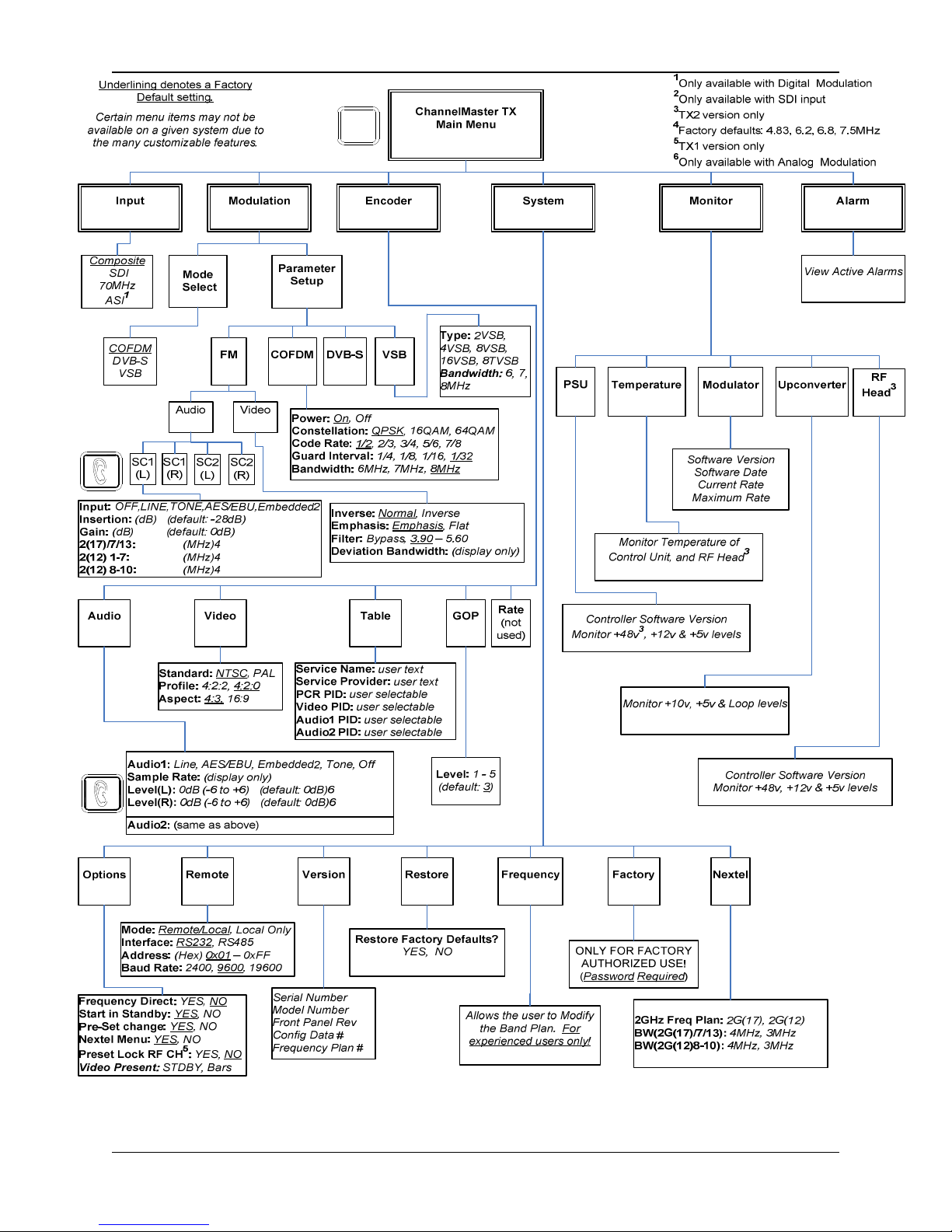
MENU
Figure 5-2 ChannelMaster Menu Tree
5-18
ChannelMaster TX1 Transmitter
 Loading...