

Page 1
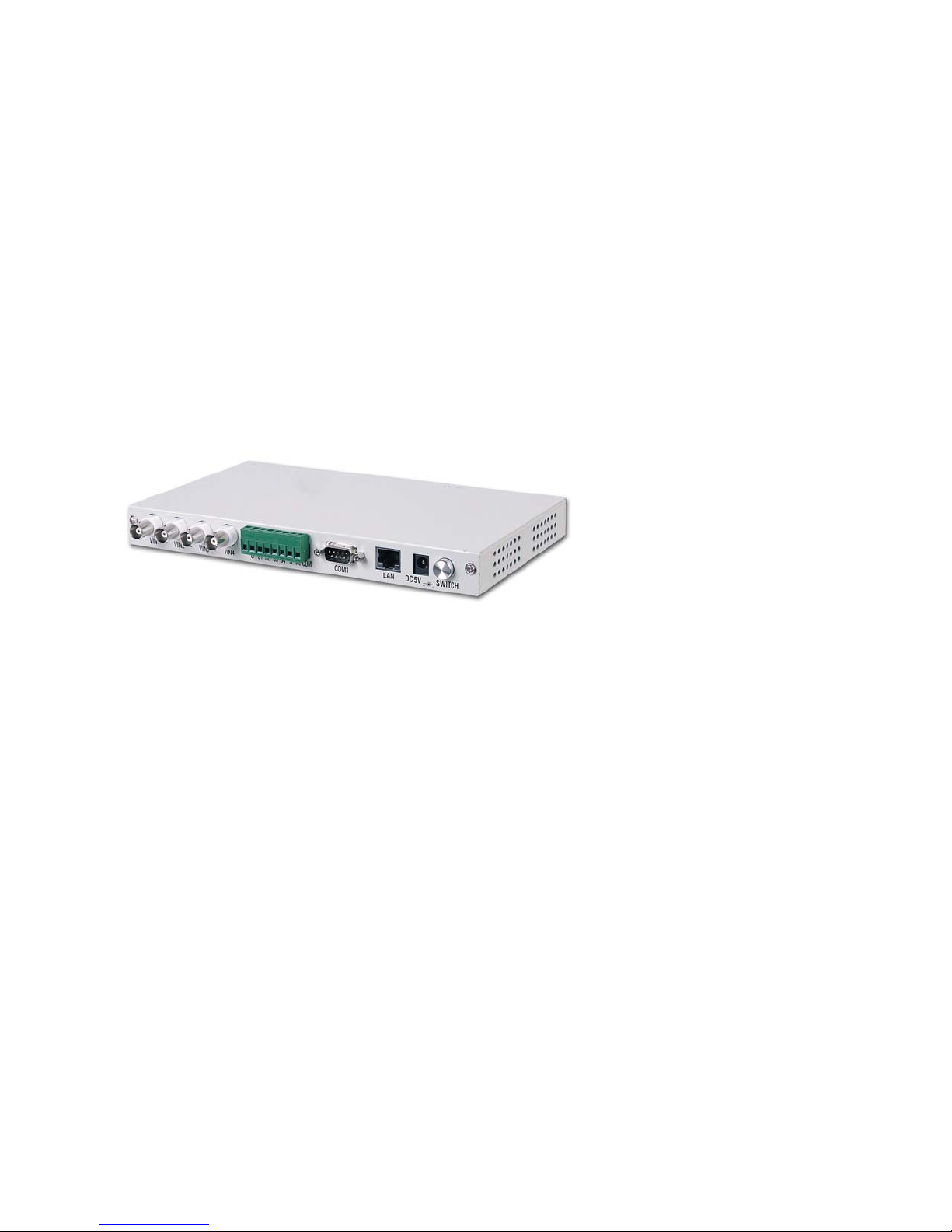
The DMP-7300 Surveillance
Webcam Server for Windows
Internet Explorer
User’s Manual
Version: 1.2
Revised: November 14, 2001
Page 2

Copyright Notice
This document is copyrighted, 2001 by Nucleus Electronics Corp all
rights are reserved. The information in the manual is subject to change
without notice in order to improve the product. No part of this manual
may be reproduced, copied, translated or transmitted in any form or by
any means without the prior written permission of the manufacturer.
Nucleus Electronics Corp. assumes no responsibility for any
inaccuracies that may be contained in this document. Nucleus
Electronics Corp. makes no commitment to update or to keep current the
information contained in this manual.
Trademarks Acknowledgments
All brand names and trademarks are the properties and registered
brands of their respective owners.
DMP-7300 Webcam Server User's Manual: Version 1.2
2
Page 3

Table of Contents
Chapter One: Start up Page
1.1 Packing list 4
1.2 Specifications 5
1.3 Front face plate 5
1.4 Rear face plate 6
1.5 Side face plates 6
Chapter Two: Installation
2.0 Installation of program: single server 7
Diagram
2.1 Installation of program: multiple server 12
2.2 Connect by modem: diagram 14
2.3 Installation of the modem 15
2.4 Installation the program: via modem 16
2.5 Connecting the sensor 19
2.6 Using webcam server via browser 20
Chapter Three: System Operation
3.1 Set configuration via browser 21
3.1.1 Security setup 22
3.1.2 Fine Tuning 24
3.1.3 Recording images to flash memory 25
3.1.4 View record 26
3.1.5 View and printing images 26
3.1.6 Set local time 27
3.2 Add/ Delete user name & password 27
3.3 Accessing the server via browser 27
Appendix A Circuit diagram of sensors 28
Appendix B Installation via: Intranet 29
Appendix C Connecting to a switch 31
Appendix D Onboard jumper and connectors 32
Q and A 33
Specifications: Addendum 34
DMP-7300 Webcam Server User's Manual: Version 1.2
3
Page 4

Chapter 1
Start up
1.1 Packing List
Product Name Package
DMP-7300
DMP-7300-EU
DMP-7300 webcam server x 1
Utility and Drivers Diskette x 1
8W Power Adapter 100V-240V
User Manual on Disk
DMP-7300
The DMP-7300 webcam server
x 1
Utility and Drivers Diskette x 1
8W Power Adapter 100V-240V,
round pin for Europe.
User Manual on Disk
DMP-7300 Webcam Server User's Manual: Version 1.2
4
Page 5
1.2 Specifications
Feature DMP-7300 WebCam Server
Chipset DMP(ALi) M6117D
Memory 8MB onboard
Protocol TCP/IP, FTP,PPP, HTTP, ARP, ICMP
IP, UDP,TCP
Network Port -10 BASE-T, IEEE 802.3
-MODEM (D-TYPE 9pin)
Connector -RJ45 connector (10Base-T)
-D-type 9 pin connector (MODEM)
-Video-in BNC connector X 4
-DC5V power connector & switch
-Terminal connector for sensor
Application support NTSC /PAL supported
Compress JPEG video compression format
Size 235mm x 140mm x 25mm
Weight 3lbs / 1.362 kg
Flash Disk Use any Compact Flash card
Power consumption DC+5V @1.6A
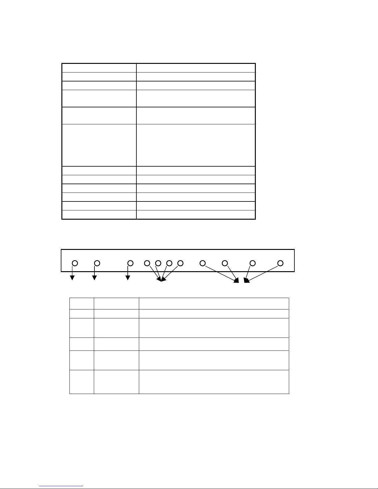
1.3 Front Face Plate
POWER ACCESS SECURITY S4 S3 S2 S1 VIDEO1 VIDEO2 VIDEO 3 VIDEO4
1 2 3 4 5
ITEM NAME FUNCTION
1
2
3
4
5
Power LED The LED should be green when the power is on.
Access LED
Security LED
Sensor LED
Video LED
DMP-7300 Webcam Server User's Manual: Version 1.2
The LED is green after you turn on the power, but when the
data is accessing through Ethernet the LED should be
blinking (red/green).
The LED is green after you turn on the power, but when you
enable the security system the LED will turn red.
The LED is off when no sensor device is connected. After
the sensor device is connected the LED will be green. And
when the sensor is triggered the LED will turn green.
When linking with a CCD camera (s), the LED is green. If
not, the LED is off. And when the CCD camera is recording
the LED will be blinking.
5
Page 6
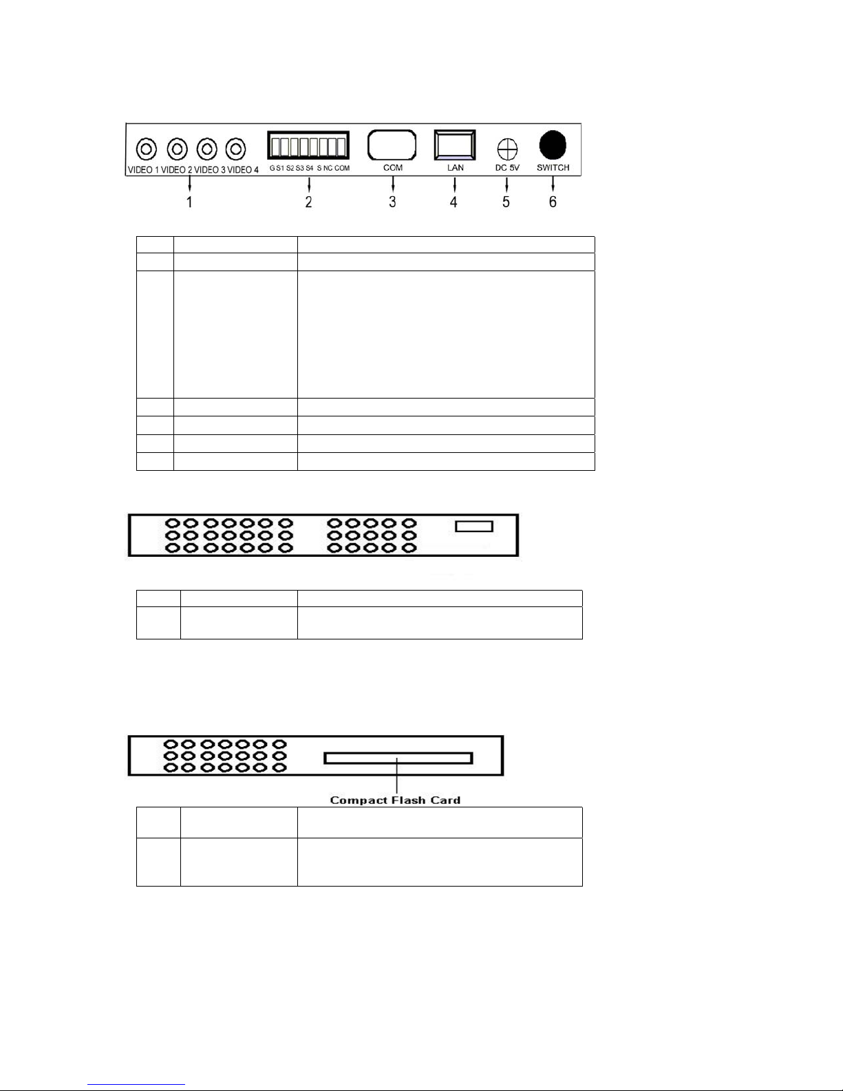
1.4 Rear Faceplate
ITEM NAME FUNCTION
BNC connector Connect to 1 to 4 CCD cameras.
1
Each CCD camera has one sensor (VIDEO1—
S1, VIDEO4—S4). You can use the micro
switch sensor to connect. When the sensor is
2
3
4
5
6
Sensor
Connector
Modem connector Link by using Modem.
LAN connector Link by using Ethernet.
Power connector Connect to DC 5V power.
Power switch Power on/off
triggered it will record automatically, also, an
alarm can be activated (if connected) (Please
see the Appendix A & section 2.5 for details)
Symbol: NC and COM: will connect to an
external alarm device. Ex speaker or horn
1.5 Side Face Plates
ITEM NAME FUNCTION
1
Dip Switches
Change when connecting to a switch or
multiplexer
Note: When connecting the webcam server to a switch or
multplexer the four (DIP) switches are to be placed in the up position.
The switches are located on the outside next to the camera ports near
the BNC ports.
ITEM NAME FUNCTION
Insert compact flash memory card
1
Flash
Note: the system must be turned off or
rebooted after adding flash memory card.
DMP-7300 Webcam Server User's Manual: Version 1.2
6
Page 7
Chapter 2
Installation
2.0 Installation of Program: Single Server
Please run the initial program (wsccfg.exe) to setup the webcam server:
By the following steps
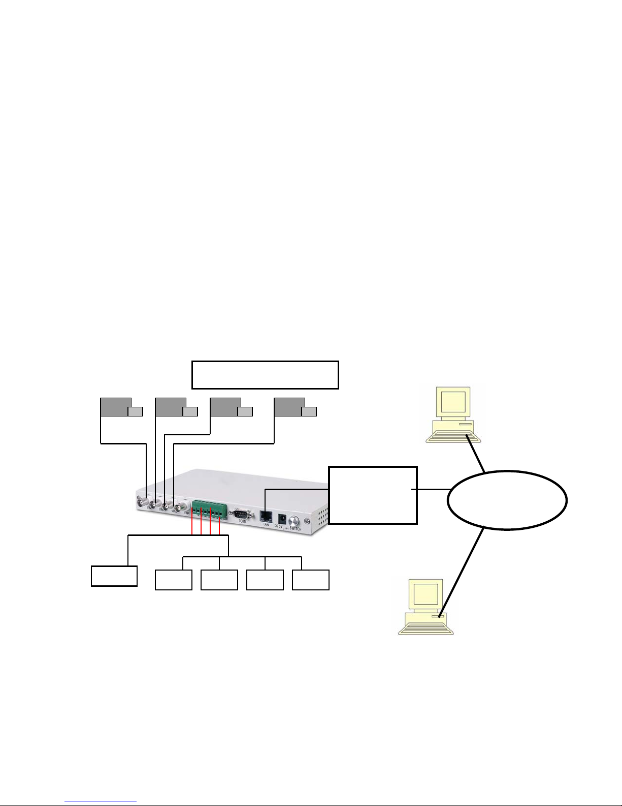
Step 1: Connect all hardware (see diagram)
a. Plug in the power cord to the server and plug into a wall
socket
b. Connect all cameras to the BNC connectors on the webcam
server.
Note: If you are connecting to a camera switch make sure
the four white (DIP) switches are in the up position. See
section 1.5
c. Plug in an Ethernet cord, using an RJ-45, to the webcam
server and connect to a hub or to the internet via T-1 or DSL.
d. Turn the power on.
Installation: Diagram
LAN:
ADSL or T-1
Via: HUB
DMP-7300 Webcam Server User's Manual: Version 1.2
-
-
-
-
7
Page 8
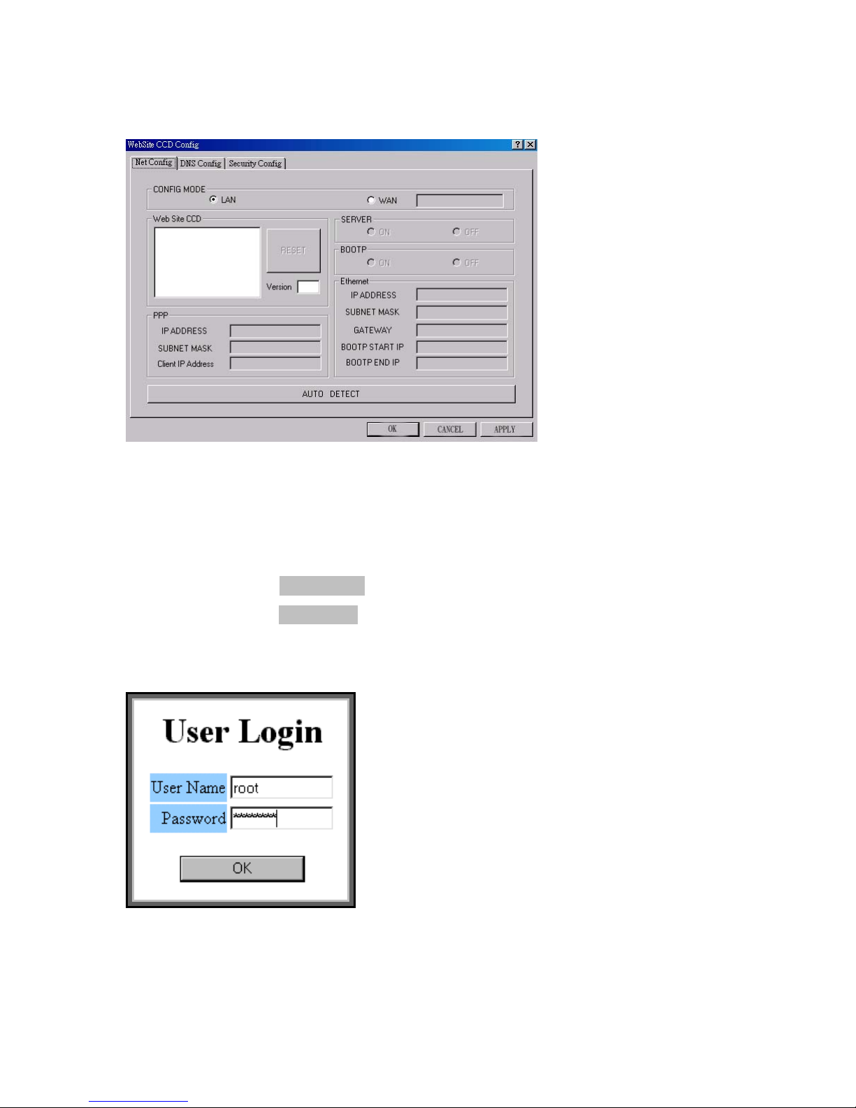
Step 2: Place the floppy disc in your host computer and run
(wsccfg.exe). The below dialog box will appear
Step 3: Click on “AUTO DETECT”
Step 4: Select or click on the MAC address in the “Website Site CCD”
dialog box
Note: Each sever has it’s own unique MAC address.
Step 5: Type in the “User Name” box: “root”
Type in the “Password” box: “password”
Click “OK”
Note: these are the default names which can be changed later.
DMP-7300 Webcam Server User's Manual: Version 1.2
8
Page 9

y
Step 6: In the Ethernet box enter its “IP ADDRESS”, “SUBNET MASK”,
and “GATEWAY”
These numbers / addresses are given to you by
your ISP and are static IP addresses.
NOTICE:
Note: Disregard the “PPP” box and entering those numbers. This is
for installation via modem only
Step 7: On the “SERVER” dialog box click “ON”
Step 8: On the “BOOTP” box click “OFF”
Step 9: Click “SAVE” or “OK”
Step 10: The webcam server which you’ve selected will be reset after
receiving a new configuration. Now you can use the browser to link the
new IP address and view the images
Note: Windows Internet Explorer is
the onl
browser it uses.
Step 11: Domain Name Setting.
Under the Modem linking mode (PPP protocol), you can browse the
WebCam Server by using both DOMAIN NAME and the IP address,
after the DOMAIN NAME setting.
DMP-7300 Webcam Server User's Manual: Version 1.2
9
Page 10
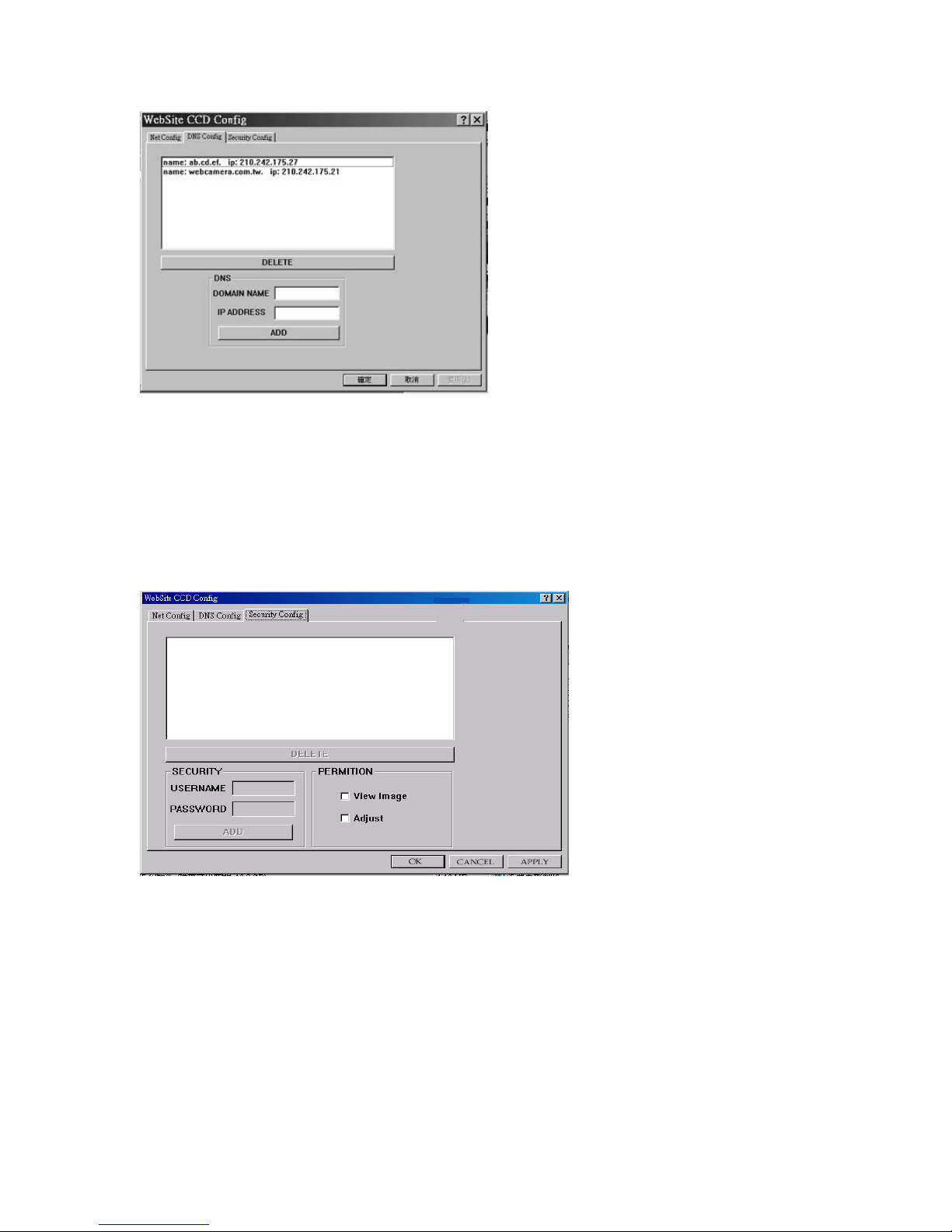
DOMAIN NAME:: Please name your WebCam Server here. (For
example: WebCam or MyHome)
IP ADDRESS: Please fill in the IP address which you set in the
Modem mode (PPP mode).
DELETE: Delete the DOMAIN NAME and IP Address which you’ve
selected.
ADD: Save new DOMAIN NAME and IP address.
Step 12: Set Security Config Tab
This dialog box is only available from the wsccfg.exe that comes
with the server.In order to change any settings you must bring
wsccfg.exe up and make any changes in this box. This allows you,
as supervisor/ administrator, to restrict who can log on and what
each user will be allowed to do. Each user is to have there own
user name, password and viewing restricti
DMP-7300 Webcam Server User's Manual: Version 1.2
ons.
10
Page 11

SECURITY: adding and deleting users
USER NAME: Fill in your username.
PASSWORD: Fill in you password.
ADD: Save the new USER NAME and PASSWORD.
DELETE: Delete the USER NAME and PASSWORD which
you’ve se
lected.
PERMISSION: for users
1. ”View Image”
a. box checked: a person can view the cameras.
b. box not
2. “Adjust”
a. box checked: a person can make security adjustments.
b. box unchecked: a person can not
adjustments.
checked: a person can not view cameras.
make security
DMP-7300 Webcam Server User's Manual: Version 1.2
11
Page 12
2.1 Installation of Program: Multiple Servers
Step 1: Connect all hardware
a. Plug in the power cord to the server and plug into a wall socket
b. Connect all cameras to the BNC connectors on the webcam
server.
Note: if you are connecting to a camera switch make sure the four
white switches, on the outside next to the BNC connectors, are in
the up position. See section 1.5
c. Plug in an Ethernet cord, using an RJ-45, to the webcam server
and connect to a hub and or to the internet via T-1 or DSL.
d. Turn on the webcam server.
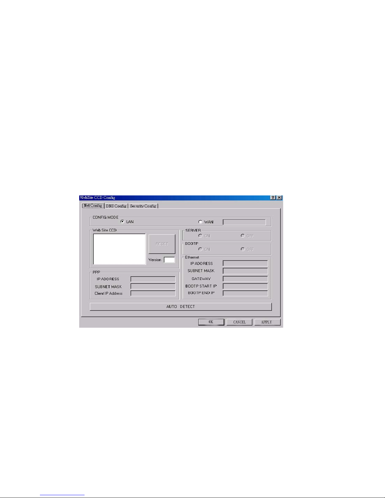
Step 2: Place the floppy disc in your host computer and run (wsccfg.exe)
the below dialog box will appear
Step 3: Click on “AUTO DETECT”
Step 4: Select or click on the MAC address in the “Website Site CCD”
dialog box
Note: Each sever has it’s own unique MAC address.
DMP-7300 Webcam Server User's Manual: Version 1.2
12
Page 13
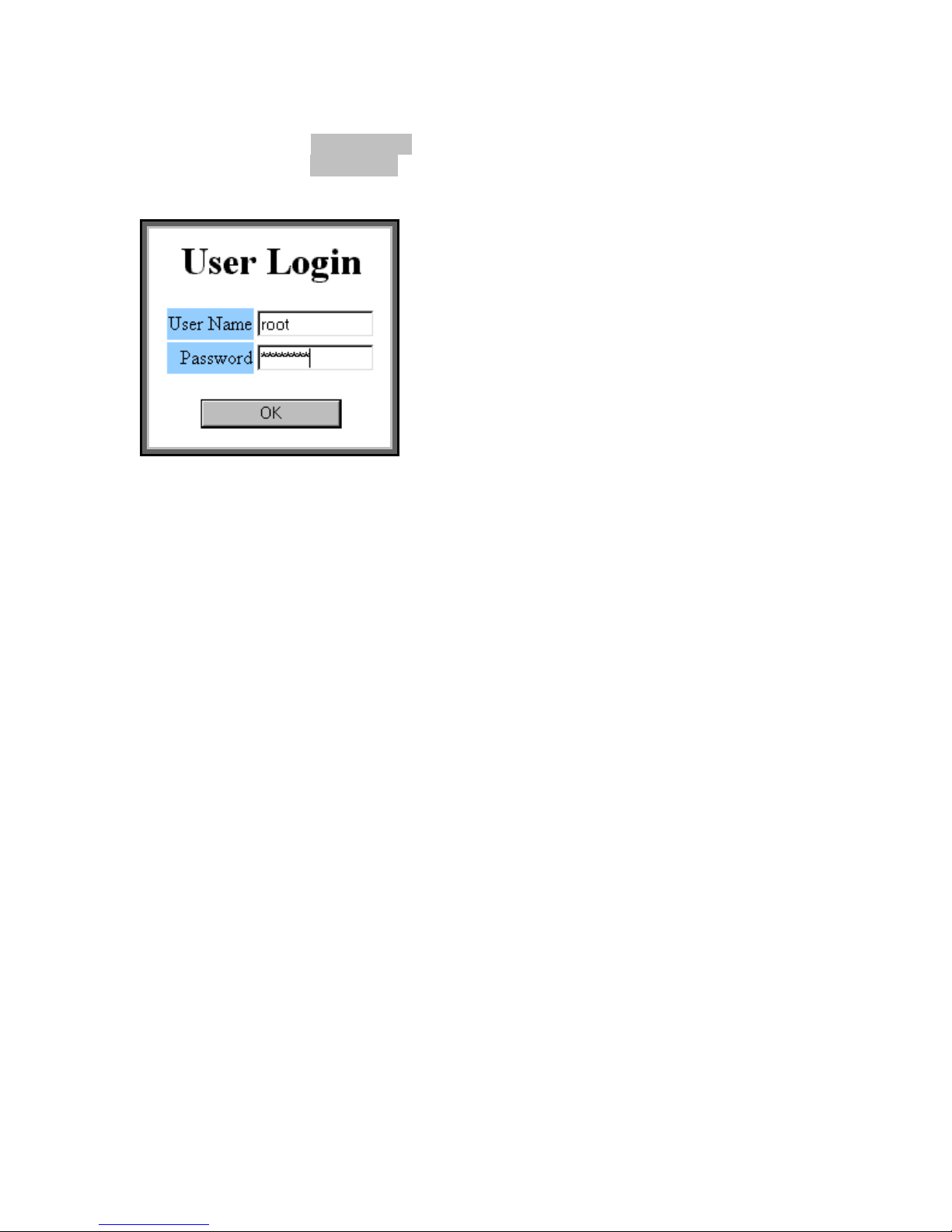
Step 5: Type in the “User Name” box: “root”
Type in the “Password” box: “password”
Note: these are the default names which can be changed later
Step 6: Enter its “IP ADDRESS”, “SUBNET MASK”, and “GATEWAY”
NOTE: these numbers / address are given to you by your ISP and
are static IP addresses. In the Ethernet dialog box the first IP
address is entered in “BOOTP START IP” and the last IP address
is entered in the “BOOTP END IP”
Note: Each server will need it’s own static IP address.
Note: Disregard the “PPP” box and entering those numbers. This is
for installation via modem only
Step 7: On the “SERVER” box click “OFF”
Note: this only applies to the 2
nd
, 3rd and 4th servers
Step 8: On the “BOOTP” box click “ON”
Note: this only applies to the 2
nd
, 3rd and 4th servers
Step 9: Type user name and password in order to manage your server.
Step 10: Click “SAVE” or “OK”
Step 11: The webcam server which you’ve selected will be reset after
receiving a new configuration. Now you can use the browser to link the
new IP address and view the images.
DMP-7300 Webcam Server User's Manual: Version 1.2
13
Page 14
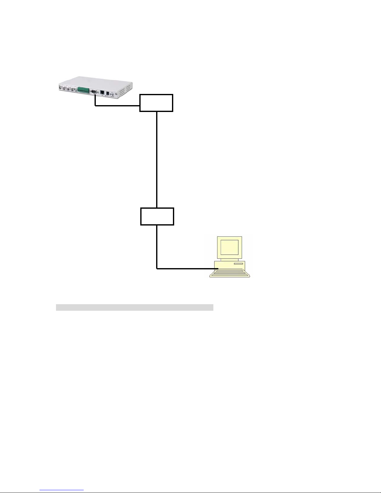
2.2 Connect by Modem: Diagram
Modem
Webcam Server
PPP/SLIP (telephone line)
Modem
Client
Note: Please connect the modem to the D-type 9 pin connector.
DMP-7300 Webcam Server User's Manual: Version 1.2
14
Page 15

2.3 Installation of the Modem
The following is for installing the modem using Microsoft’s Windows
Step 1: Connect all hardware
a. Plug in the power cord to the server and a wall socket
b. Connect all cameras to the BNC connectors into the webcam
server.
Note: if you are connecting to a camera switch make sure
the four white switches, on the outside next to the BNC
connectors, are in the up position.
c. Plug in a D-type 9 pin connector. to the webcam server and
connect to a modem and connect to phone jack (RJ-11)
d. Turn on the webcam server via power button
Step 2: From the Microsoft window click on “My computer”
Step 3: Click on “ Dial-up Networking”
Step 4: Click on “Make New Connection”
Step 5: In the dialog enter any name and enter the device name. This,
the device name, is given by the mfg.
Step 6: Click “Next”
Step 7: In the dialog box enter the phone number that you want to call
(the modem next to the Webcam server)
Step 8: Click “Next”
Step 9: Click “Finish”
Note: This process must be done on each computer when
accessing the webcam server.
DMP-7300 Webcam Server User's Manual: Version 1.2
15
Page 16
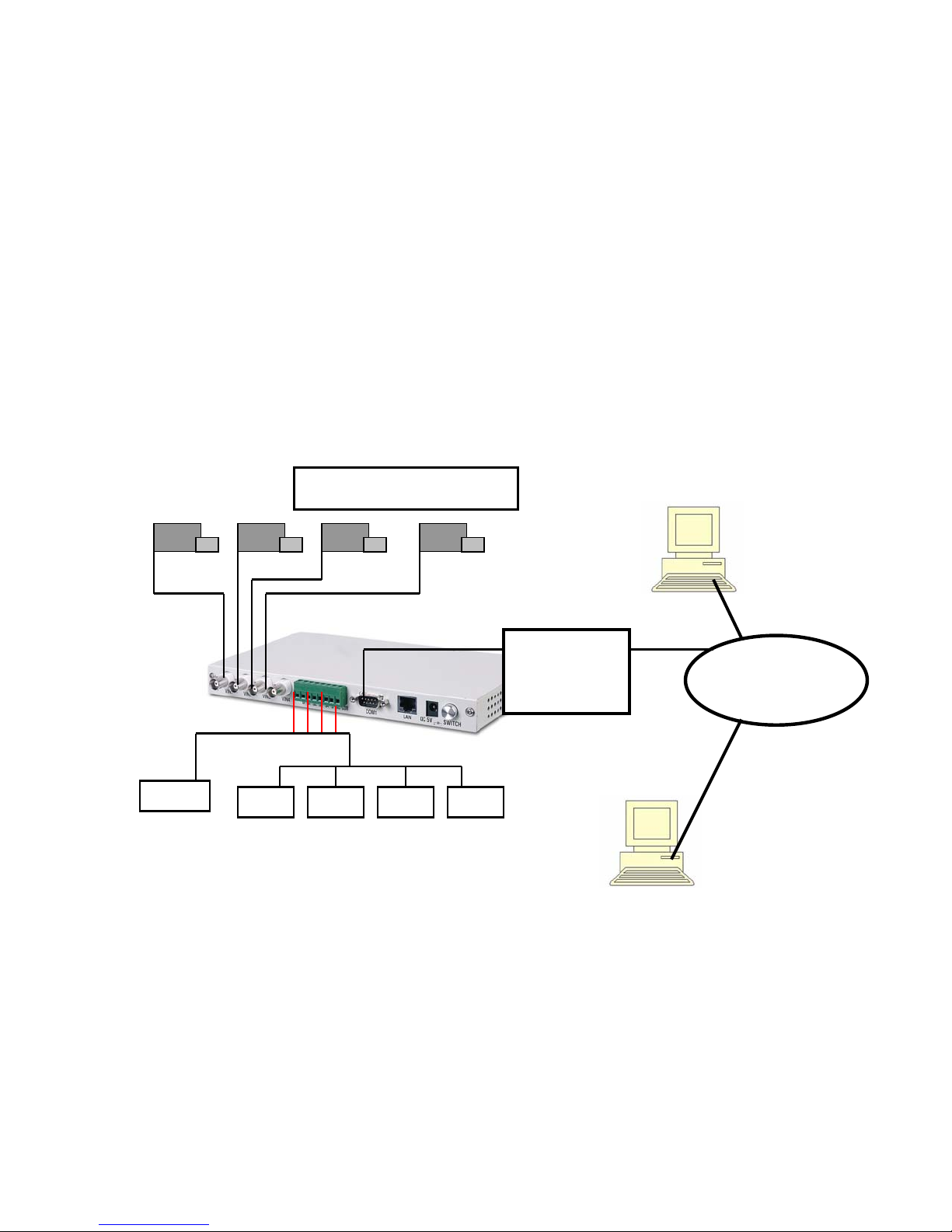
2.4 Installation of the Program: Via modem
The following is for installing the program with the modem currently
installed: If not see section 2.3
Step 1: Connect all hardware
a. Plug in the power cord to the server to a wall socket
b. Connect all cameras to the BNC connectors on the webcam
server.
Note: if you are connecting to a camera switch make sure
the four white (DIP) switches, on the outside next to the
BNC connectors, are in the up position. See section 1.5
c. Plug in a 9 pin connector to the webcam server and connect to
a modem and plug the modem into a phone jack (RJ-11)
d. Turn on the webcam server via power button.
Installation: Diagram
Modem:
to RJ-11:
phone jack
-
-
-
-
Step 2:From Microsoft window click on “My Computer”
Step 3: click on “Dial-up Networking”
DMP-7300 Webcam Server User's Manual: Version 1.2
16
Page 17
Step 4: Click on to the name of the modem that you have previously
installed. See section 2.3
Step 5: In the dialog enter a name and enter the phone number that you
will be dialing to access the webcam server.
Step 6: Click “Connect”
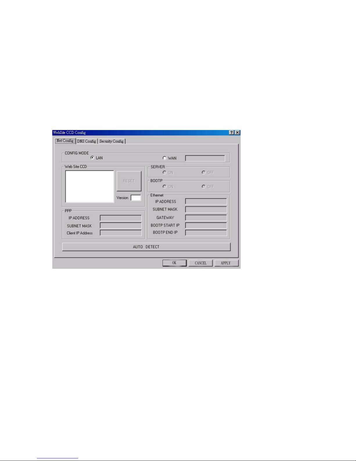
Step 7: Place the floppy disc in your host computer and run (wsccfg.exe)
the below dialog box will appear
Step 8: Click on “AUTO DETECT”
Step 9: Select or click on the MAC address in the “Website Site CCD”
dialog box
Note: the webcam sever has it’s own unique MAC address.
DMP-7300 Webcam Server User's Manual: Version 1.2
17
Page 18
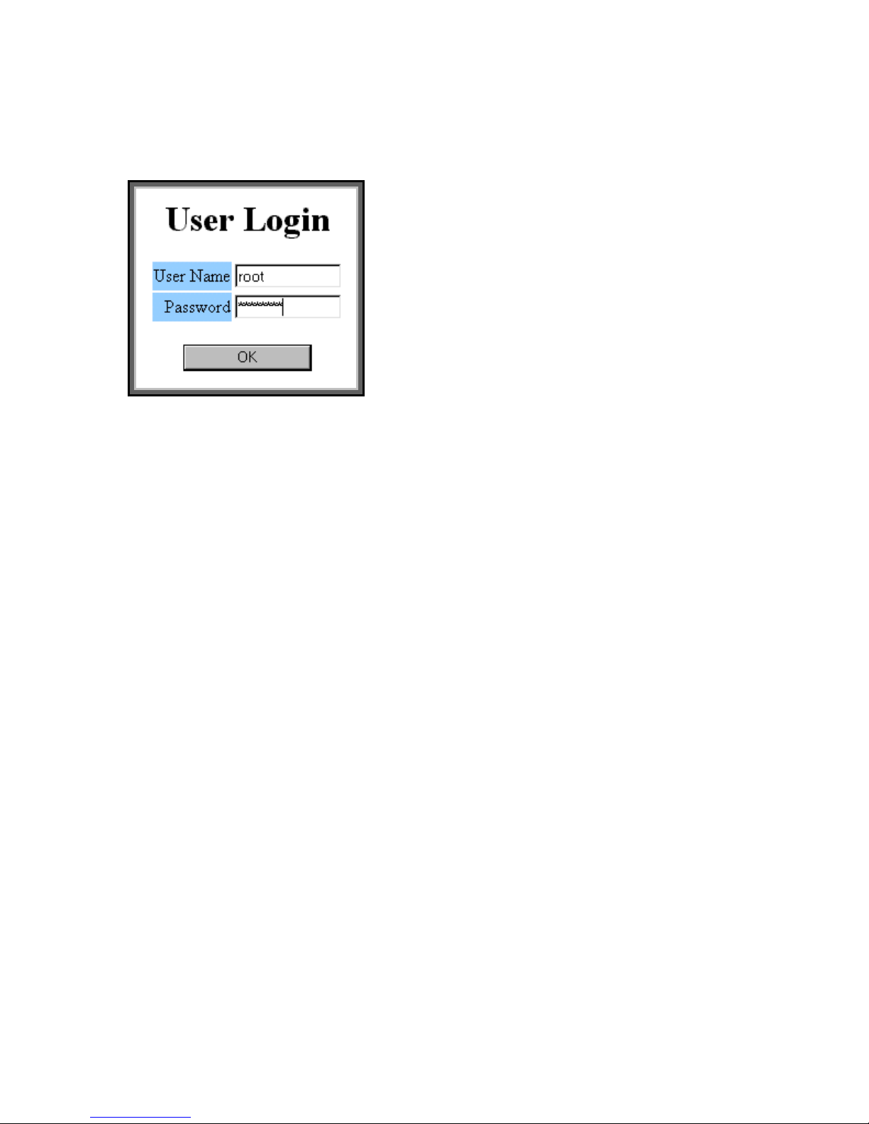
Step 10: Type in the “User Name” box: “root”
Type in the “Password” box: “password”
Note: these are the default names which can be changed later
Step 11: In the “PPP” dialog box the default: 192.168.1.1 will appear in
the “IP ADDRESS”. If it does not appear then enter 192.168. with the
next two number sets to be any numbers from 1 to 254
Example: 192.168.24.67 or 192.168.185.92 ………….
Step 12: Enter the following in the:
SUBNET MASK: 255.255.255.0
Step 13: For the “Client IP Address” 192.168.24.2~254
Note: in the 3
rd
place it must the same number as the “IP
ADDRESS” with the fourth to be a random one.
Step 14: On the “SERVER” dialog box click “ON”
Step 15: On the “BOOTP”dialog box click “OFF”
Step 16: Click “SAVE” or “OK”
Step 17: Type user name and password in order to manage your server.
Step 18: The webcam server which you’ve selected will be reset after
receiving a new configuration. Now, you can use the browser to link the
new IP address and view the images.
Note: You can only use one server when connecting to a modem.
DMP-7300 Webcam Server User's Manual: Version 1.2
18
Page 19

2.5 Connecting the Sensors:
Step 1: From each external sensor device connect the ground wire from
each of the four sensors and connect the wire to input marked
“G”. All of the four ground wires are to be connected to the “G”
or ground input.
Step 2: Then connect the other sensor wires to there
Appropriate numbers: sensor device 1 to “S1” etc.
Step 3: When the sensors have been installed see section
3.1.1 to design the system.
Optional:
Step 4: The two places marked “NC” and “COM” are for
an external alarm devices such and alarm sound or
for calling the police or the security alarm company.
See Appendix A for the wire diagram.
DMP-7300 Webcam Server User's Manual: Version 1.2
19
Page 20
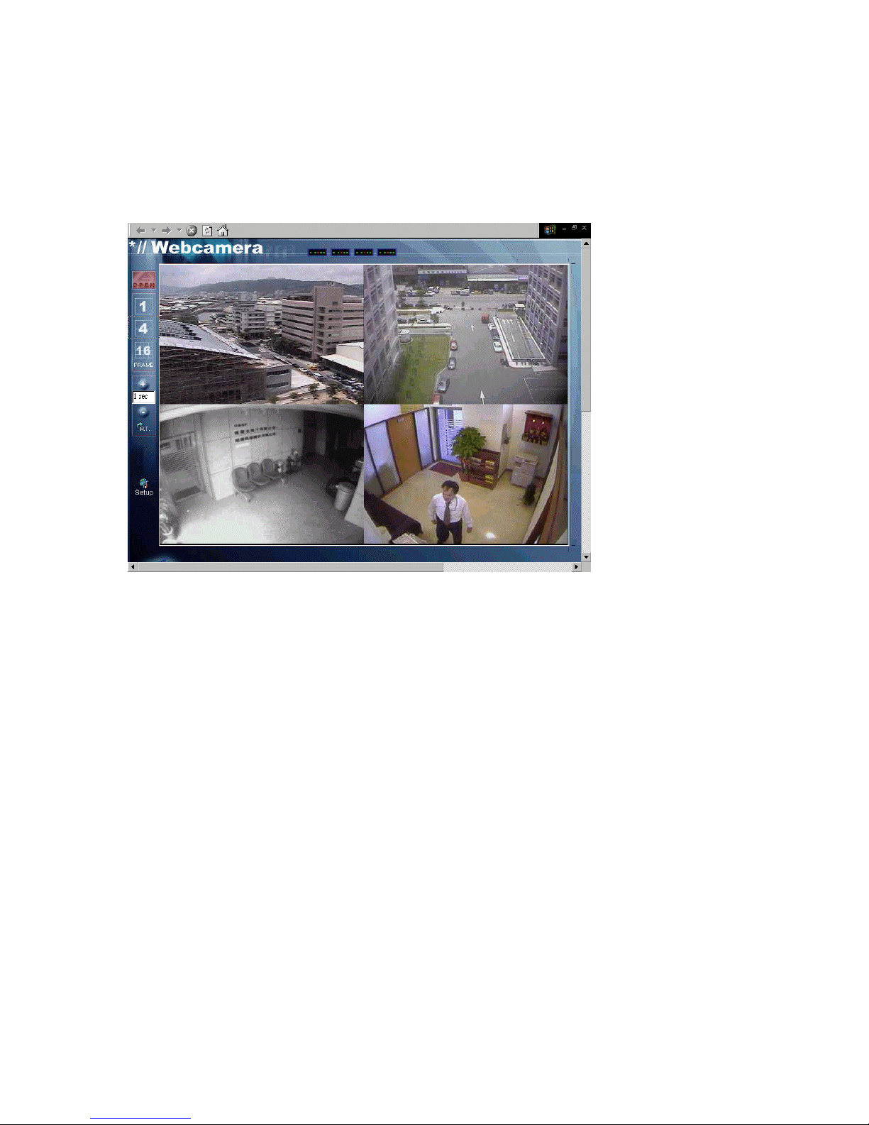
2.6 Use WebCam via Browser
Please press the "Open" button to start viewing the camera images.
You choice 1, 4, or 16 frame and adjust the Refresh Time (R.T.). The
Refresh Time is from 0.1 second to 10 min, which means the browser
will send a request commend to the webcam server every 0.1 second to
10 min. And after the server receives the request from the browser it will
send the image to the browser.
Note: Setting the frame rate or “RT” @ .1 gives me a faster frame or
refresh rate, but you will miss some frames. Setting @ 30 seconds gives
a slower frame rate but you will see more images. Setting @ one (1)
second gives a good combination.
DMP-7300 Webcam Server User's Manual: Version 1.2
20
Page 21
Chapter 3
System Operation
3.1 Set Configuration via Browser:
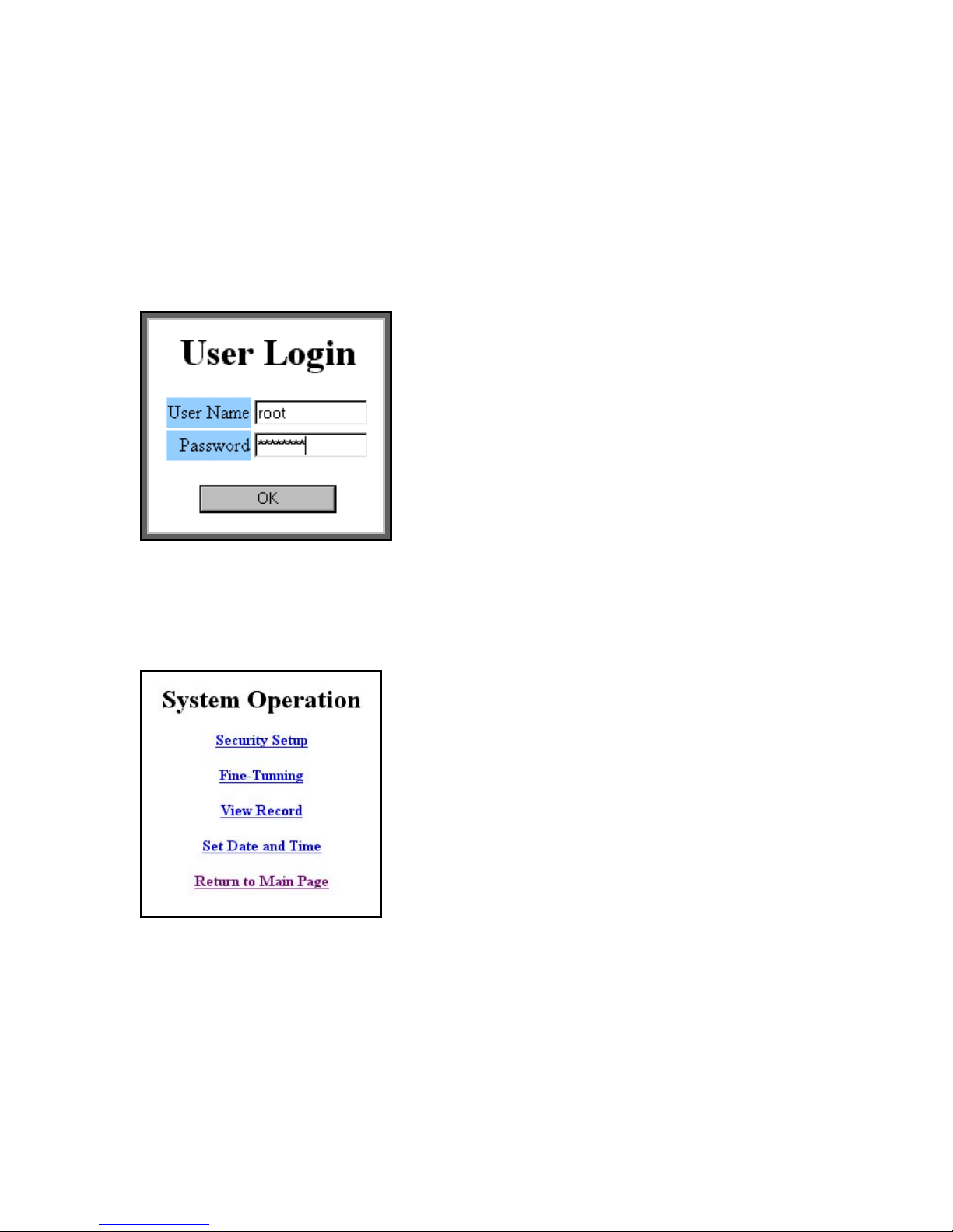
Press "Setup" icon to enter the system operation:
The default user name is "root" and default password is "password".
The DMP-7300 webcam server will ask the user to key-in the password
and user name the first time to access setup page. After the login
process a “System Operation” page will be seen as below:
DMP-7300 Webcam Server User's Manual: Version 1.2
21
Page 22
3.1.1 Security Setup:
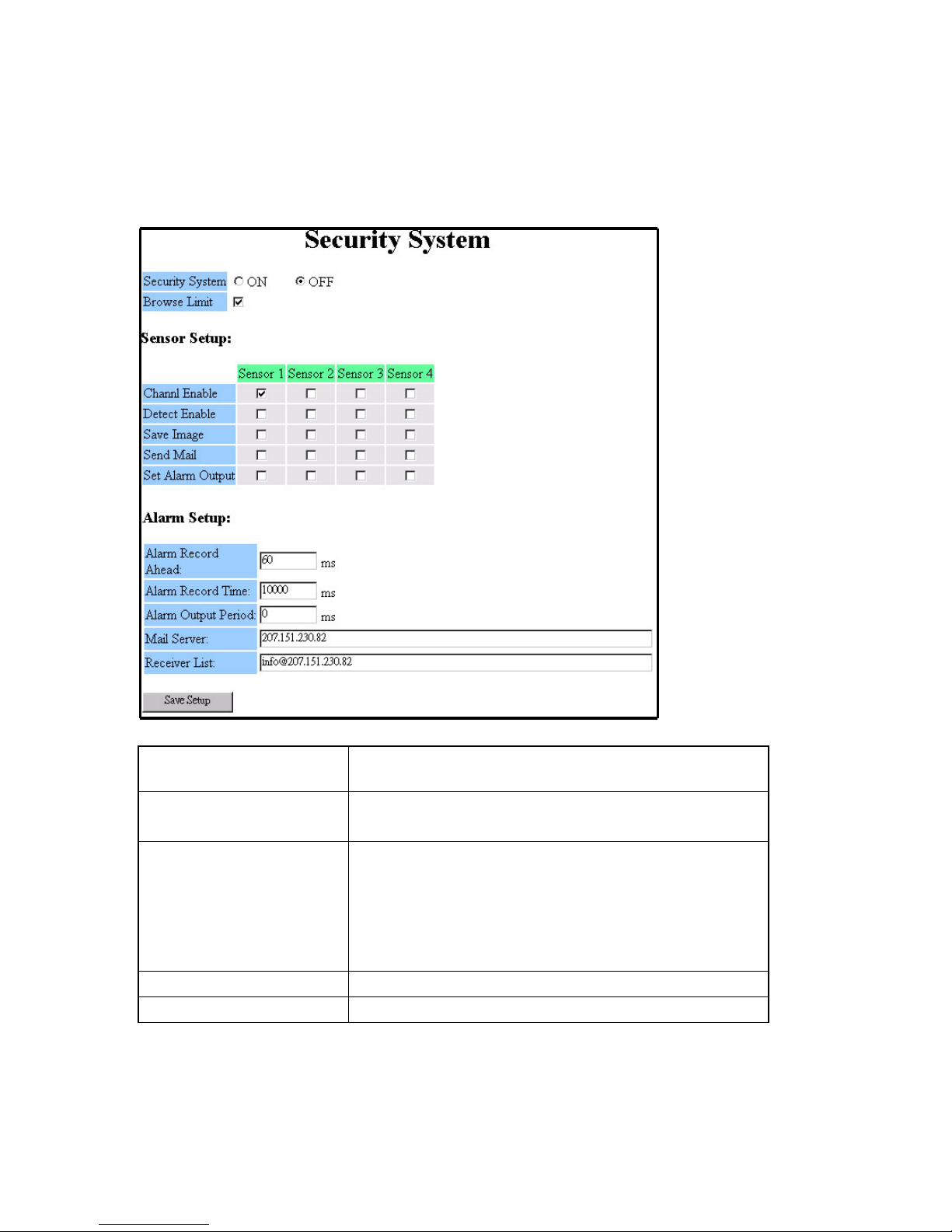
You can set the security system in the dialog box
below: Also see section 2.0 Step 12 for more details.
Security System
Turn ON/OFF security system.
On: person can view cameras
Browse Limit
Off: person cannot view cameras
Allows viewing any camera on screen that you
select, even if you have connected the CCD
Channel Enable
camera(s) to the WebCam server, the pictures
will not shown on browser if you didn’t enable
the channel. Disabling the sensors when not
using the cameras when give clearer images.
Detect Enable
Save Image
DMP-7300 Webcam Server User's Manual: Version 1.2
Enable/disable the detection.
Save image or not when alarm is triggered.
22
Page 23

Send Mail
Set Alarm Output
Send mail when alarm is triggered.
Server will set alarm output when alarm is
triggered.
Record Ahead
Ahead
Alarm Record Time
Alarm Output Period
Mail Server
Save images before the alarm is triggered.
Save images after the alarm is triggered.
Set the time that alarm will sound
Server will use this mail server to send mail.
This E-mail address will receive an alarm
Receiver List
message when alarm is triggered.
Press "Save Setup" to save new configuration or press "Reset" button to default status.
Note: 1000 MS or millisecond = One (1) second
If you enable send mail an alarm is triggered you will receive a alarm
message as below:
Received: from [210.242.175.25] by XXX; Wed, 6 Jun 2001
18:19:04 +0800
From: WebCam
To: email address
Subject: Alarm Mail from Web Cam(210.242.175.25)
Date: Wed, 6 Jun 2001 18:19:03 +0800
Message-Id: <[email protected]>
This mail is sent by WebCam to notify the channel0 was triggered
at 2001/06/06 - 18:24:53
Images were recorded as event-id 0005. Link to
http://210.242.175.25/recevent.jgi to view images.
3.1.2 Fine-Tuning
DMP-7300 Webcam Server User's Manual: Version 1.2
23
Page 24
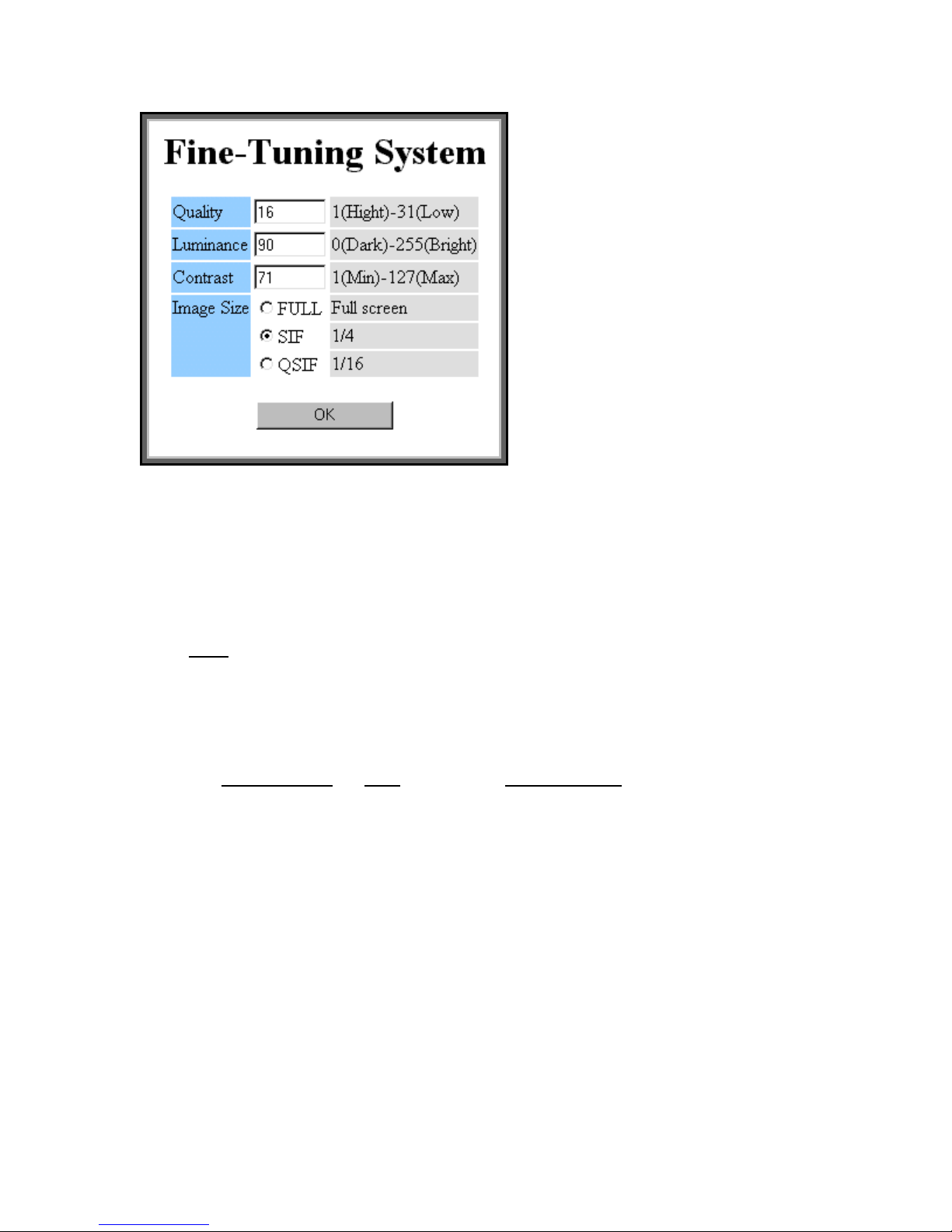
Quality From: 1 to 31: 1 is the best quality and 31 is the lowest.
Luminance From: 0 to 255, dark to bright.
Contrast: From 1 to 127, min to max.
Image Size: Image size when sending picture from
the webcam server to your browser. If you choice SIF or QSIF, the
picture will be compressed in the webcam server before sending.
Note
:
FULL: gives better image quality but slower frame rate.
QSIF: gives faster frame rate but less image quality
SIF: a good middle setting
For example:
Quality:High
Full 150K 30K
SIF(1/4) 40K 12K
SQIF(1/16) 15K 4K
: Q=1 MediumQ=16
DMP-7300 Webcam Server User's Manual: Version 1.2
24
Page 25

3.1.3 Recording Images to the Flash Memory
Step1: Connect all cameras and sensors see sections: 2. 0 , 2.5 and
appendix A.
Step 2: See section 3.1.1 in the “Security System” dialog box and
configure the system to fit your requirements.
Step 3: In the “Sensor Setup” section select the functions that you want
the sensors to perform.
Step 4: In the “Recording Setup” section there are 2 boxes
A. “Record ahead” the DMP-7300 webcam server has RAM, which
is recording and recycling the 4 camera images. By selecting this
time function when a sensor is triggered it will record ahead, from
RAM, of the time prior to the sensor being triggered. Example: by
setting the “Record Ahead” for 10 seconds it will record the
intrusion of what you set (10 seconds) plus the time you select in
the “Record Time” section
B. “Record Time” when a sensor is triggered this will record the
length in which you programmed the time to record into the internal
flash memory. Note: This is set by milliseconds 1000
ms
1 second
=
Step 5: Three settings will affect the flash memory space: A. “Fine
Tuning System”: “Quality” section 3.1.2 The lower the number
(1,2,3…) the more memory is consumed and the higher the number
(12,13,14…) the less memory is consumed.
B. “Record Time” section 3.1.1. The more time you want the system
to record the more memory is consumed
C. “RT” Refresh Time section 2.6. In ”The return to main page”
there are two buttons a plus (
number the more frames will be recorded into memory and the
higher the number the less frames will be recorded, therefore
affecting flash memory capacity.
Note: Reboot after installing additional compact disk.
DMP-7300 Webcam Server User's Manual: Version 1.2
) and a minus (-). The lower the
+
25
Page 26
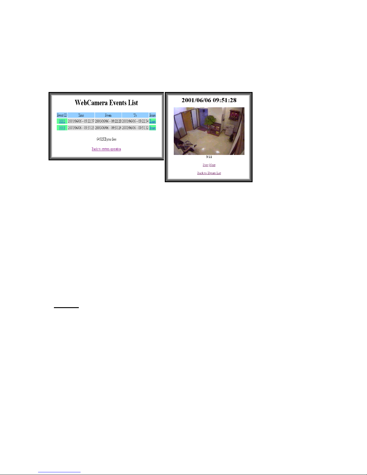
3.1.4 View Record
All the images that had been saved will be listed in the dialog box
below. You can press "Event ID" to view images or "Erase" to delete
them.
When the sensor is triggered photos and the time will be saved
automatically. You can view the pictures and time in “WebCamera Event
List”
3.1.5 Viewing & Printing Images:
To print the event to your printer click onto the event that you want to
view and those series of pictures will appear. As you flip thru select the
frame you want to print and from the tool bar select print.
Note: These images are saved to the internal flash disc and to the
additional flash memory card See section 1.5 . Once the memory is full it
will not
See “WebCamrea Event List” dialog box.
DMP-7300 Webcam Server User's Manual: Version 1.2
continue to save the images. You must erase the flash card.
26
Page 27
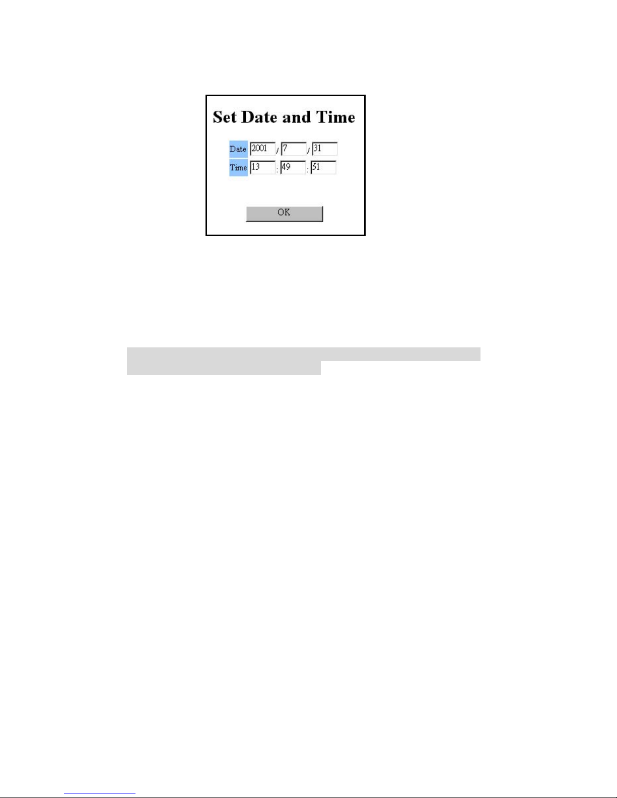
3.1.6 Set Local Time
Set your local date and time in the Webcam server
3.2 Add/Delete User and Password
Select "Security Config" tab to add/remove/change the user
name and password.
We recommend users to change default user name and password
when you install the Webcam server
3.3 Accessing the Server via Browser
In order to access the webcam server via internet or via modem
enter its IP address or its PPP IP address.
Note: The webcam server only works with
Microsoft’s Internet Explorer.
DMP-7300 Webcam Server User's Manual: Version 1.2
27
Page 28
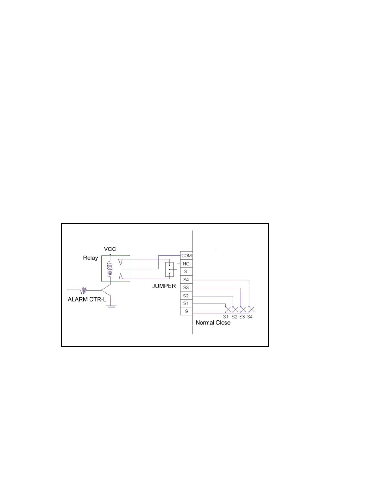
Appendix A
Circuit Diagram of the Sensors
SENSOR:
The build-in switch sensors in the WebCam Server are NC (Normal
Close) sensor. It’s just like the sensors which are used on doors or
windows. Usually the doors and windows are closed, but when the doors
or windows are opened the circuit becomes “open”, then the security
system in the WebCam Server will be active by the way you set it in the
“SECURITY SETUP”.
ALARM:
The alarm output sensor in the WebCam Server is a NO (Normal Open)
sensor. Which means when the alarm is triggered the circuit will be
“short”, then the alarm will be active.
DMP-7300 Webcam Server User's Manual: Version 1.2
28
Page 29
Appendix B
Installation via: Intranet
Step 1: Go to the DOS prompt
Step 2: Type in “ipconfig” press enter
Step 3: Three series of IP address numbers will appear
In this form on your computer.
IP Address 192.168.2.24
Subnet Mask 255.255.255.0
Gateway 192.168.2.32
Copy those numbers down
Step 4: Type in “exit”
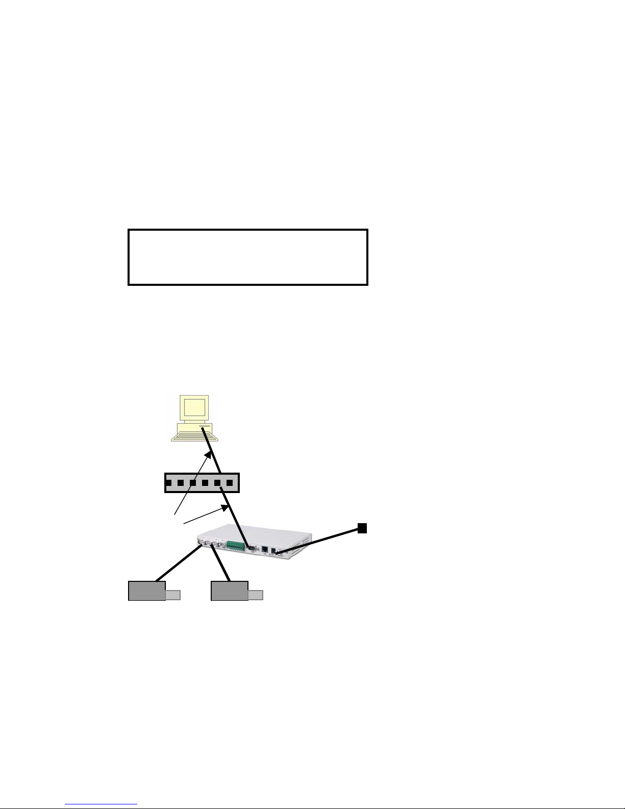
Step 5: Connect all Hardware as shown below
Host Computer
Network HUB
Ethernet cord
Step 6: Place the floppy disc and run the Wsccfg.exe
DMP-7300 Webcam Server User's Manual: Version 1.2
Power Cord
29
Page 30
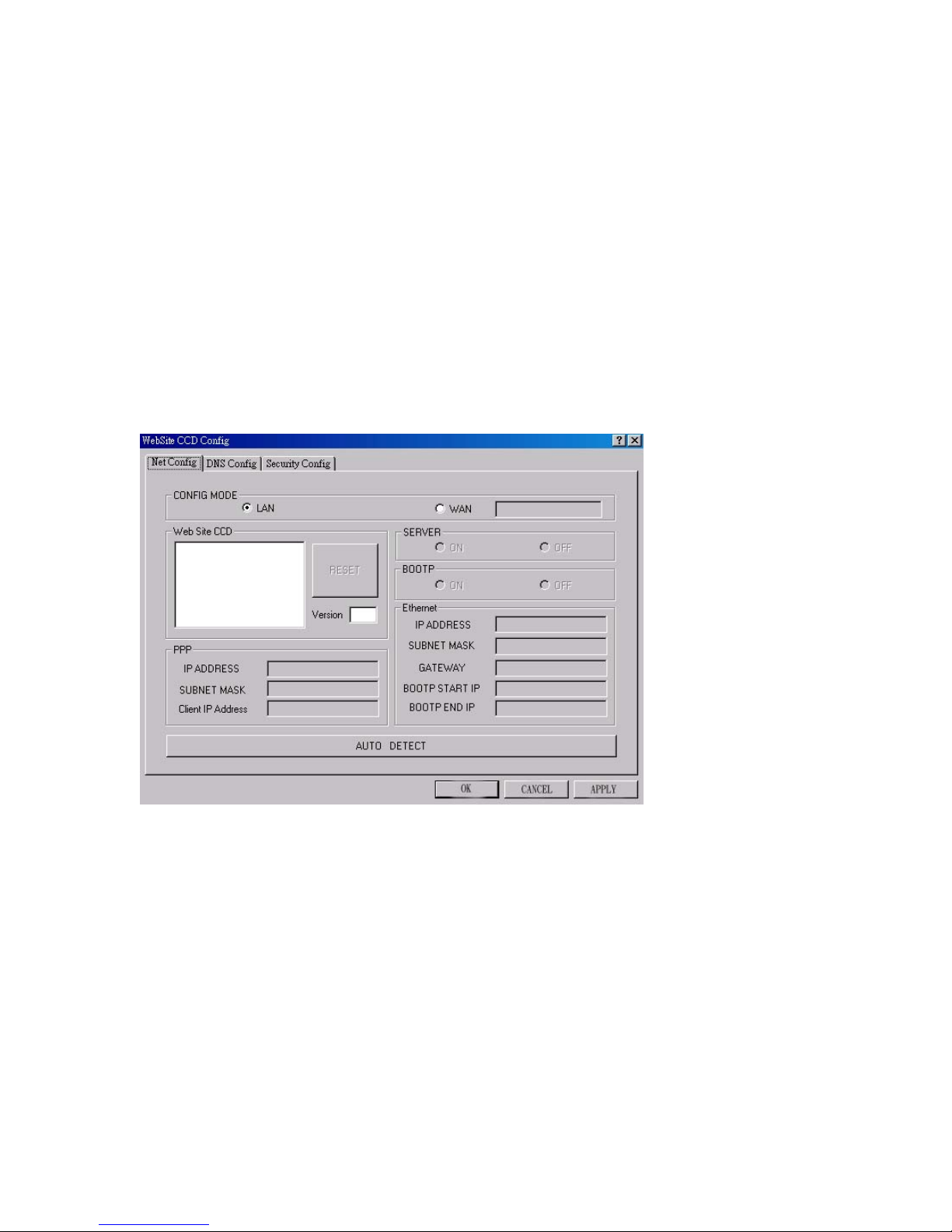
Step 7: Click on “AUTO DETECT”
Step 8: Type in your user and password
Step 9: Type the in the IP numbers that you copied in step 3
However in the 4
th
place, in the “IP Address” box, replace that
number with any number from 1-255 (except 24 or 32) these
numbers, 24 and 32, are used as an example when connecting to
your system. Those numbers will reflect the numbers that appear
on your computer.
IP Address 192.168.2. 1-255 (except 24 or 32)
Subnet Mask : 255.255.255.0
Gateway: 192.168.2.32
Step10: click “OK”
Step 11: Open your computers Window’s Explorers browser and enter
the IP address: 192.168.2. 1-255 (except 24 or 32)
Note: In the example the only variable is 24 which must be
replaced with any number (except 24 or 32)
Step 12: Installed
DMP-7300 Webcam Server User's Manual: Version 1.2
30
Page 31
y
p
Appendix C
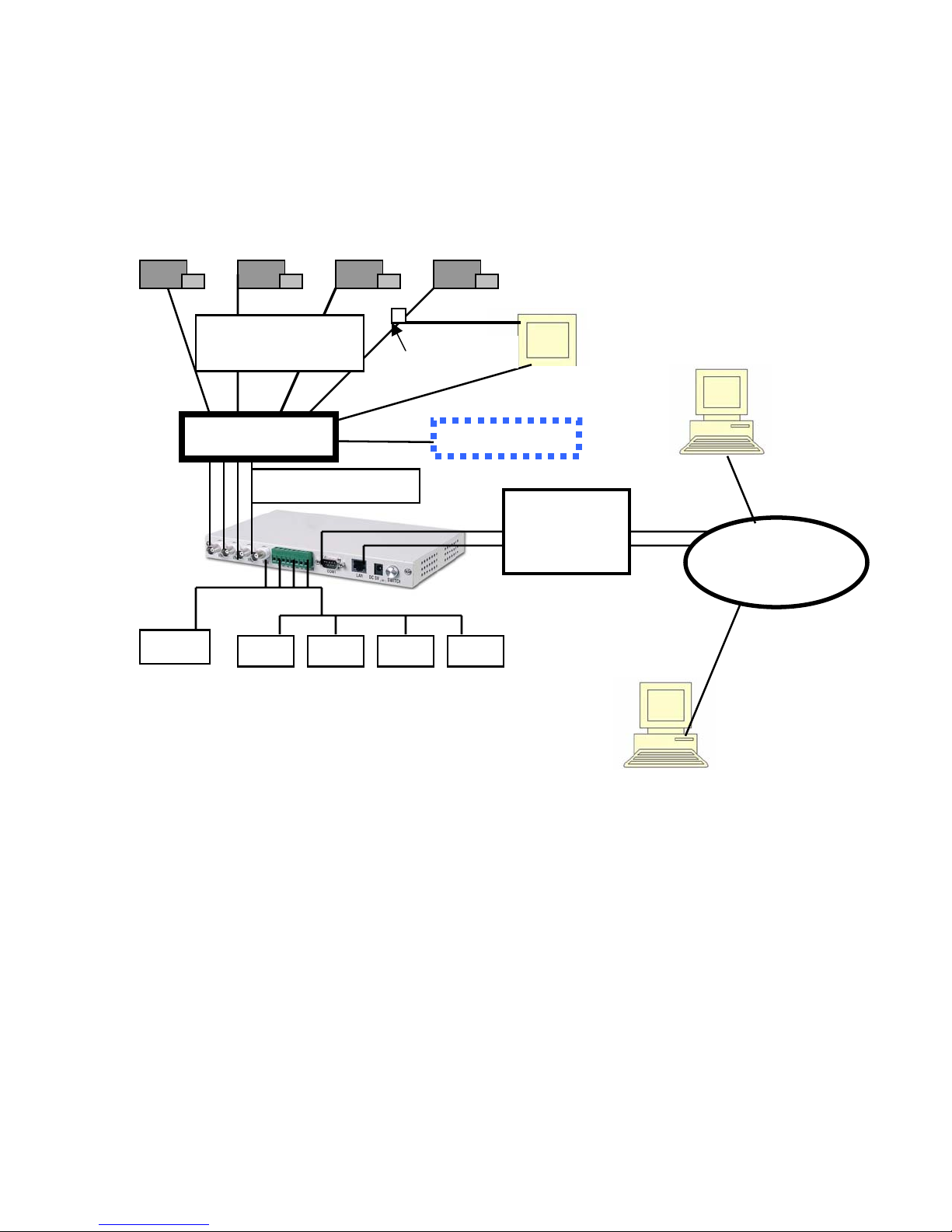
Diagram of installation connecting to a video switch
B: Splitter / quad
(O
Video Switch
*
tional)
B: Splitter / quad
T-Connector
VCR recorder
LAN:
Modem,
ADSL
Monitor
Internet
Rela
*
In most cases you will need four inputs and four
outputs connecting to and from the video switch.
A splitter or quad, as see in box B, can be used if the video
switch does not have four input or output jacks.
T-Connector: when connecting any of the cameras to a T-connector one
dip switch per camera must moved into the UP position.
DMP-7300 Webcam Server User's Manual: Version 1.2
-
-
-
-
31
Page 32
Appendix D
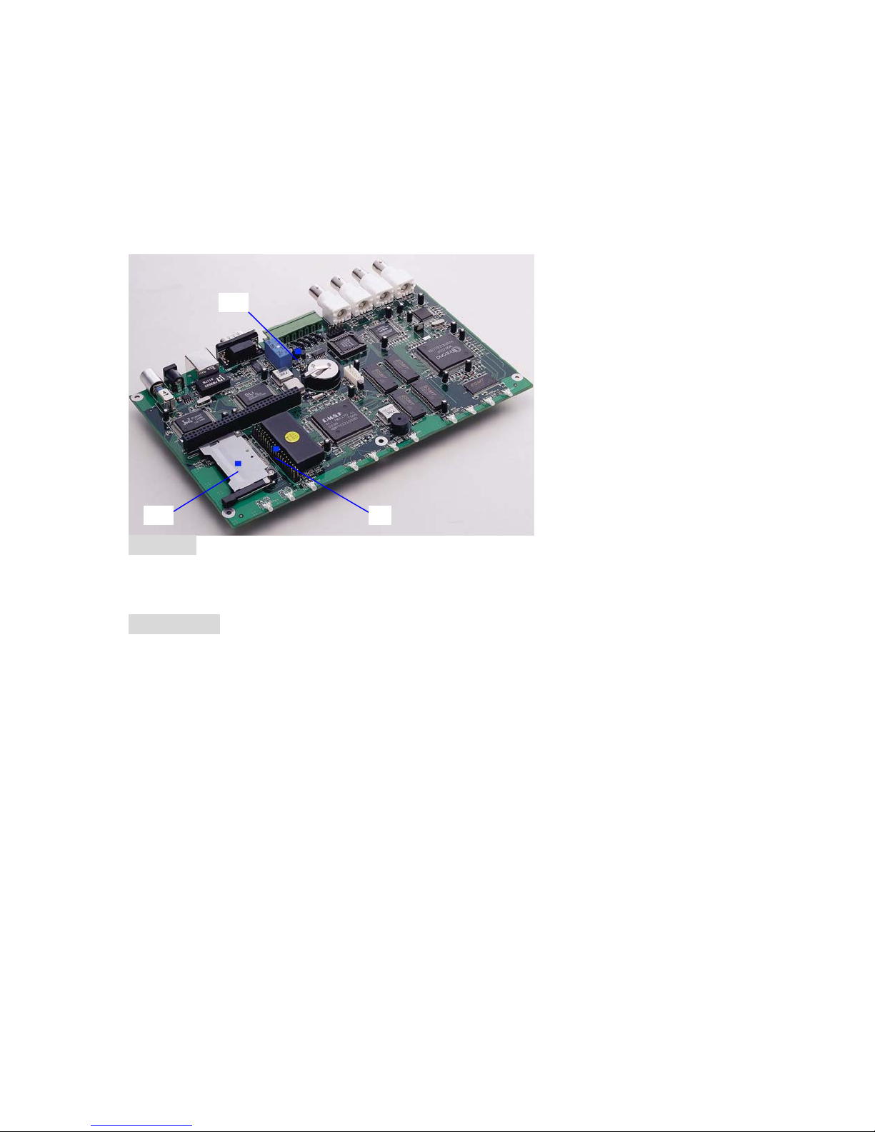
Onboard jumper and connectors.
J12
CF J4
Jumper:
J12: Alarm NC/NO jumper
1- 2: NC
2- 3: NO
Connector:
J4: IDE 40 pin connector for MicroDisk Module or HDD.
CF1: Compact Flash Card socket
DMP-7300 Webcam Server User's Manual: Version 1.2
32
Page 33

Questions and Answers
1. When connecting the internet can I use a “T” connector along with
the computer in connecting to the LAN?
Answer: No, when connecting to the Webcam server to the
internet if you nave more than two nodes you must us a hub.
2. What browser interfaces can I use?
Answer: Windows Internet Explorer only. It will not
other browser.
3. Where and how can I view my cameras over the internet?
Answer: From any Windows Internet Explorer browser site.
type in the IP address, user name and password. No additional
software is needed on the computer from where you are viewing.
4. What kind of cameras can I use?
Answer: You can use a B/W or color CCD cameras. The better
cameras and lens that you use the better clarity you will have.
5. I connected the webcam server my pictures are fuzzy what’s
wrong?
Answer: When connecting the webcam server to a switch or
multiplexer the four (DIP) switches are to be placed in the up
position if not the switches are to placed in the down position. The
switches are located on the outside next to the BNC ports. See
section 1.5
work with any
DMP-7300 Webcam Server User's Manual: Version 1.2
33
Page 34

Specifications: Addendum
Controller:
CPU: DMP M6117D (386SX-40MHz)
8 MB Memory
Ethernet: 10Base-T RJ-45 connector
RS-232 D-type 9-pin connector
Video-in by 4 BNC connector
Video:
NTSC / PAL support
Video input for 4 independent channels
Separated view windows support from full screen / 4 windows 16
windows
Indicators for 4 channels activity
Recorder (trigger by sensor):
Sensor/Alarm: 4 set NC/NO connector map to 4 channels video-in
Capacity of storage: 1 internal Compact Flash slot can install up 256MB
CF card
User's option to record time range before/after trigger enabled
Record frame can be view by any windows internet explorer
Compression:
JPEG Video compression format
Resolution:
Full screen: 704 x 480
CIF: 352 x 240
QCIF: 176 x 112
Communication interface:
RJ-45
10Base-T Ethernet
DMP-7300 Webcam Server User's Manual: Version 1.2
34
Page 35

Configuration:
HTTP web-page- Internet Explorer
Setup program:
Performance:
Ethernet: frame updated from 0.1 sec to 10 min. (static) Modem: frame
updated from 1 sec to 10 min. (static)
Protocol
IP ,ICMP ,ARP, PPP, HTTP ,FTP
Power supply request
Input: +5V DC
8 Watt
Size
Metric: 235(L)*140(W)*25(H) mm
American: 9’’ x 5 ½ ’’ x1”
NUCLEUS
1016 A Lawson St. City of Industry, Ca. 91748
Ph: (626) 581-4560 FAX: (626) 581-4169
Website: www.nucleus1.com
DMP-7300 Webcam Server User's Manual: Version 1.2
Electronics Corporation
35
 Loading...