

Page 1
Water-Jacketed Automatic CO
Incubator
2
Models
NU-8600, NU-8600E
NU-8631, NU-8631E
Operation and Maintenance Manual
November 2018
Revision 6
Series 3
For 115 Vac, 50/60 Hz Only
Manufactured By:
NuAire, Inc.
2100 Fernbrook Lane
Plymouth, MN 55447
Toll-Free: 1-800-328-3352
In Minnesota: (763)-553-1270
Fax: (763)-553-0459
Page 2

Water-Jacketed Water Jacket Invitrocell CO2 Incubator
Operation & Maintenance Manual
NU-8600, NU-8600E
NU-8631, NU-8631E
Table of Contents
Section No. 1 ..................................................General Description
Section No. 2 ..................................................Performance Parameters and Features
Section No. 3 ..................................................Models & Features
Section No. 4 ..................................................Test Performance & Procedures
Section No. 5 ..................................................Warranty Statement Notice
Section No. 6 ..................................................Shipments
Section No. 7 ..................................................Installation
Section No. 8 ..................................................Water Jacket Operation
8.1 ..............................................Sterility
8.2 ..............................................Humidity
8.3 ..............................................Control System Introduction
8.4 ..............................................NuTouch Display Screen
8.5 ..............................................Rear Component Panel
8.6 ..............................................Run Mode Operator Interactions
8.7 ..............................................Standby Mode Operator Interactions
8.8 ..............................................Front Component Panel
8.9 ..............................................Diagnostic Interactions
8.10 ............................................Resetting the Electronic Software
Section No. 9 ..................................................Calibration
9.1 ..............................................Chamber Temperature Calibration
9.2 ..............................................Door Heater Adjustments Affecting Temperature Calibration
9.3 ..............................................Setting Air Injections
9.4 ..............................................CO
9.5 ..............................................O
Section No. 10 ................................................Maintaining Your Water Jacket Invitrocell
10.1 ............................................Heated Decon Cycles
10.2 ............................................Chemical Decontamination
10.3 ............................................Shutting down the incubator
10.4 ............................................Automatic Filter Change Notification
Section No. 11 ................................................Error Indicators & Troubleshooting
Section No. 12 ................................................Communication Outputs
Section No. 13 ................................................Electrical/Environmental Requirements
Section No. 14 ................................................Disposal and Recycle
Insert ......................................................Replacement Parts List
BCD-18002 .................................................................. Dimensioned Assembly NU-8600
BCD-19905 .................................................................. Interior prep
BCD-15170 .................................................................. Rear Component Panel Assembly
ASSEMBLY DRAWINGS
BCD-18476 .................................................................. Front Component Panel
BCD-18477 .................................................................. Sensor Bay Assembly
BCD-19455 .................................................................. Right Hand Door Assembly
BCD-19456 .................................................................. Left Hand Door Assembly
ELECTRICAL SCHEMATICS
BCD-18364 .................................................................. Electrical Schematic
BCD-18007 .................................................................. Main Control Board Electrical Schematic
Calibration
2
Calibration
2
MANUAL DRAWINGS
OM0253 Page 2 of 53
Rev 6 November/2018
Page 3

Water Jacket
Invitrocell CO2 Incubator
Model: NU-8600, NU-8600E, NU-8631, NU-8631E
Operation and Maintenance Manual
1.0 General Description
The NuAire Water Jacketed Incubator has been designed to provide a reliable controlled In-vitro environment for optimum
tissue cell culture growth. The chamber also provides an environment for the storage and preservation of gametes and animal
tissue cell cultures intended for research at or near body temperature.
There are five parameters that contribute to optimum growth conditions, they are:
Humidity
Precise temperature control
Precise CO
Sterility
Reliability
Like all NuAire equipment, this Incubator has been designed to provide the highest quality standards of performance with
matching computer technology, precise temperature control, and CO
with years of design, quality, and manufacturing experience.
1.1 Extra Large (18 to 20 gallon) Water-Jacket - Each Chamber
The outer stainless steel wall is lined with a space-age insulation providing a R5.0 rating, minimizing heat loss. The large 20
gallon (75.7 liters) Water-Jacket utilizes water, one of nature’s best "sinks" of heat. Its high capacity to hold heat makes it
the ideal medium to surround a chamber in order to obtain temperature uniformity. In fact, the ability of materials to hold
heat, called the specific heat, uses water as the comparative standard. The large water-jacket surrounding the chamber
permits the water to circulate within the jacket, producing a temperature uniformity of ±0.2°C. The larger the mass, the
less susceptible the environment within the chamber is to environment fluctuations outside. It also adds cabinet stability
for the growth of vibration sensitive cells.
1.2 Incubator Closed loop chamber sample circulation system & HEPA Filter
A continuous operating air pump draws environmental sample from the chamber and circulates it through a HEPA filter
capsule then through sensors that measure CO
control
2
gas control system combining state-of-the-art technology
2
volume (as a percentage) in the chamber for monitoring and control.
2
1.3 Incubator Control Electronics
The NuAire Incubator Control Electronics is a state-of-the-art microcomputer based control system specifically designed to
service the precise control requirements of the chambers environment, providing optimum programmable conditions for
culture growth. The microcomputer is “user-friendly” and provides a 5x7 LCD screen which provides operating control
parameters, status indicators, additional key operational parameters, and an imbedded touch panel to permit efficient
operator entry of data.
The microcomputer is supported with Read Only Memory (ROM) containing executable software, Random Access Memory
(RAM) for temporary storage, and Electronically Erasable Programmable Read Only Memory (EEPROM) for control set
points and parameters. The EEPROM provides for indefinite storage of these values during periods of power off or power
interruption (power fault tolerant).
1.4 Incubator CO
The NuAire direct heat Incubator incorporates a microprocessor-based, non-dispersive infrared CO
The amount of energy received at the detector is an approximate logarithmic function of the CO
between source and detector. The wavelengths used are absorbed only by CO
Control
2
induction sensor.
2
concentration in the gas
2
making the measurement insensitive to
2
other components, such as water vapor. Detector linearization is performed with 32 bit digital accuracy. Advanced design
provides a very stable output minimizing drift and requiring less frequent calibration. The output is digital, alleviating errors
brought about by analog signals. Calibration of this control is accomplished by a zero & span calibration done on the sensor
and a display off- set calibration. These calibrations are accessible through the NuTouch LCD located on the front of the
unit.
OM0253 Page 3 of 53
Rev 6 November/2018
Page 4

1.5 All Stainless Steel Construction
The exterior is constructed of 16 gauge, type 304L stainless steel with the interior being 16 gauge, type 304L polished
stainless steel using coved corner construction, which provides an easily cleanable (for decontamination) inert surface that
does not promote biological growth. All exposed edges are deburred to insure no sharp edges. The exterior is finished in a
textured polyurethane finish, which is resistant to chemicals and easily cleaned using mild household detergents. In
addition all shelves, shelf supports and guide rails are easily removable and can be autoclaved to remove contamination.
Remember: The chamber environment is not selective. The growth environment is applied equally to all microorganisms
(specimens and contaminates) within the chamber.
1.6 Incubator Humidity
All Model(s)
A relative humidity level of up to 90% is achieved in the Incubator by the use of a stainless steel pan filled with distilled
water no purer than 1 mega ohm, and placed on the bottom of the chamber. It is necessary to set the duty cycle of the
door heater in proper proportions to reduce the possibility of condensation forming on the glass inner door and the
chamber walls. It is also important to thoroughly wipe the walls and the glass door clean before adding the humidity water
pan. Condensation will occur more readily at contamination points. There is no electronic sensing and thus no automatic
control of the humidity level in the Water Jacketed Incubator. An air pump injects fresh air into the chamber at a preset
duty cycle to reduce condensation forming on the chamber walls and front glass door. The air injections are settable by the
user to help control condensation. (See section 8.8 for this option.)
1.7 O2 Display and Control (NU-8631)
The Incubator has an available optional Oxygen display and control system. The system controls from 21% (ambient level)
down to 0.5%. The recovery time from ambient to 5% ± 2% is typically less than 15 minutes. The accuracy is ±0.25% from
any given set point.
Oxygen sensor is a type, which generates logarithmic signal based on O
by CO, H
and various acidic gases such as CO2, etc.
2
1.8 Safety Instructions
content in the chamber. The sensor is unaffected
2
These safety instructions describe the safety features of the INVITROCELL Incubator.
The incubator has been manufactured using the latest technological developments and has been thoroughly tested before
delivery. It may, however, present potential hazards if it is not used according to the intended purpose or outside of
operating parameters. Therefore, the following procedures must always be observed:
•
•
The incubator must be operated only by trained and authorized personnel.
For any operation of this unit, the operator must prepare clear and concise written instructions for operating and
cleaning, utilizing applicable safety data sheets, plant hygiene guidelines, and technical regulations, in particular.
o Which decontamination measures are to be applied for the incubator and accessories?
Which protective measures apply while specific agents are used?
o
Which measures are to be taken in the case of an accident?
o
•
Repairs to the device must be carried out only by trained and authorized expert personnel.
•
Keep these operating instructions close to the unit so that safety instructions and important information are
always accessible.
•
Should you encounter problems that are not detailed adequately in the operating instructions, please contact your
NuAire Representative or NuAire technical Services.
OM0253 Page 4 of 53
Rev 6 November/2018
Page 5
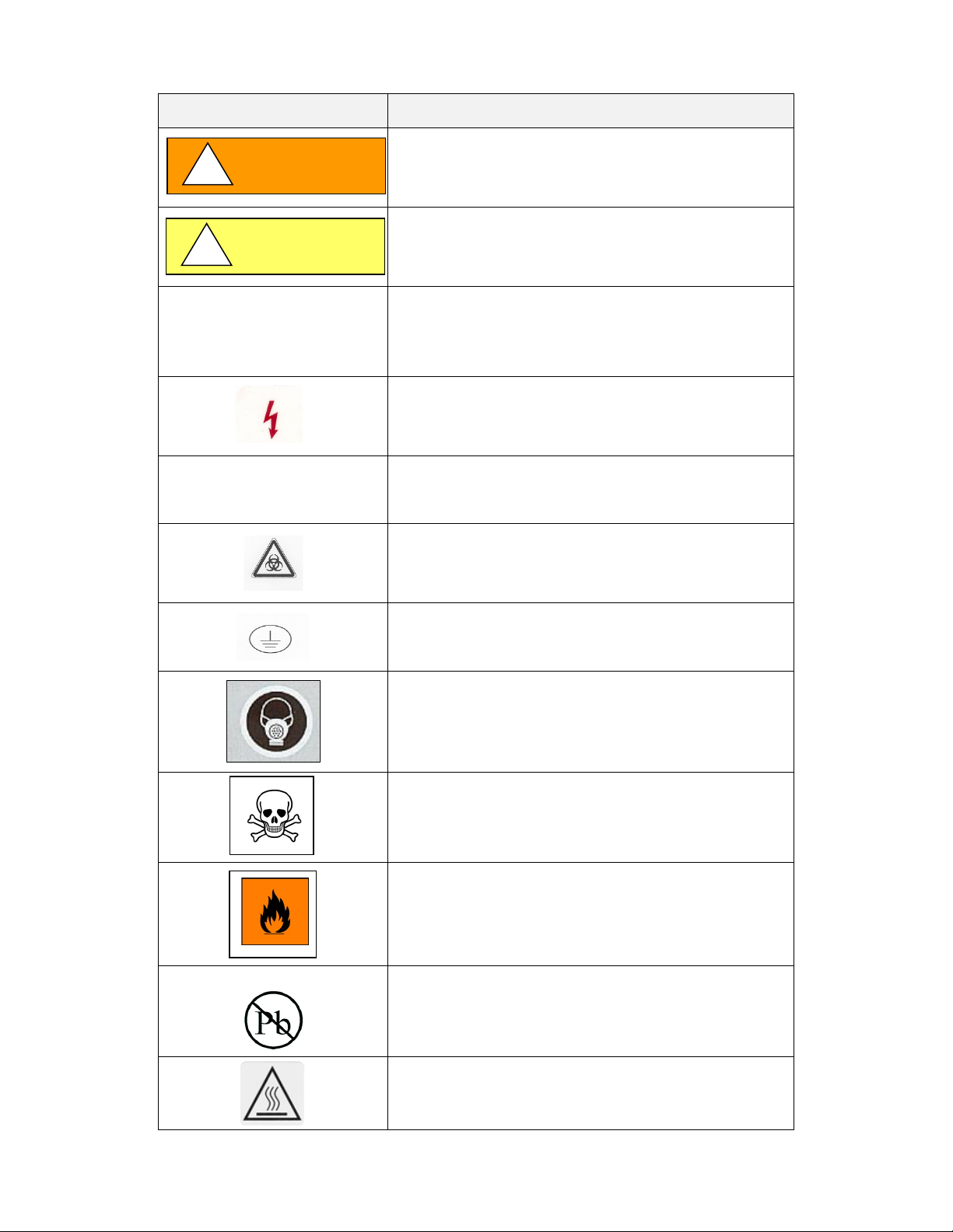
1.9 Explanation of symbols
CAUTION
!
WARNING
!
Symbol (in text box) Description (in text box)
Safety alert symbol indicates a potentially hazardous
situation which, if not avoided, could result in death of
serious injury.
Safety alert symbol indicates a potentially hazardous
situation which, if not avoided, may result in minor or
moderate injury.
CAUTION
CAUTION used without the safety alert symbol indicates a
potentially hazardous situation which, if not avoided, may
result in property damage.
Potential electrical hazard,
only qualified person to access.
Note:
Biohazard
Ground, Earth
Hazardous Gases!
Personal Protection Equipment Required.
OM0253 Page 5 of 53
Rev 6 November/2018
Chemical Hazard
Flammable Hazard
Lead Free
Hot Surface
Burn Potential
Page 6

2.0 Performance Parameters and Features
• Each chamber's water-jacket holds 18 to 20 gallons (up to 75.7 liters) of water that, in conjunction with the
microcomputer control system, provides an interior chamber temperature uniformity of ±0.2°C at 37.0°C.
• The microcomputer temperature control system has two temperature sensors located inside the chamber at the back
wall. The temperature sensors compare the values to a set point and execute a differential control algorithm that
energizes a solid-state switch, supplying power to the heaters.
• Easily removable inner shelves and rails for sterilization.
• Up to 16 shelves can be placed inside the chamber (4 shelves are shipped).
• Space-age high temperature material is used to insulate the Water Jacket walls.
• Most electronics, motors, pumps, and valves are fully accessible from the back of the unit.
• A CO
• The CO
• After a door opening the CO
sample port is provided on the front panel just below the door to check the concentration of CO2 in the chamber.
2
percentage is controlled by a solid-state gas infrared sensor using a single light source with dual wave length
2
detection, providing accurate monitoring of CO
level automatically recovers to 5.0 + 0.2/- 0.5% within a 5 minute period on average.
2
• The outer door includes an internal radiant heater in order to minimize condensation on the inner glass door.
A magnetic outer door gasket helps to insure a tight seal against the cabinet.
• The inner glass door is 3/16” tempered with smooth-ground edges and seals are tight against a silicone rubber gasket.
The door latch is cam action.
A momentary switch monitors the door position, the position being opened or closed.
• All control electronics are protected with a circuit breaker that may trip at 110% of loading rating but will trip at 145%
of load rating in less than 2 seconds.
Should the circuit breaker open (pop-out button will appear), merely depress to reset.
• The Incubator has adjustable leveling legs to compensate for uneven laboratory surfaces.
.
2
OM0253 Page 6 of 53
Rev 6 November/2018
Page 7

3.0 Models & Features
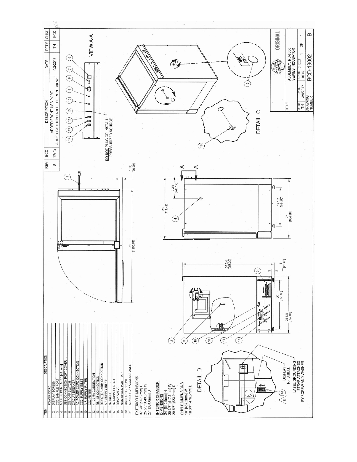
3.1 Dimensions (see also Specification Drawing BCD-18002)
Overall Dimensions - inches (mm): All Models
Height: Exterior: 37.750 inches (958 mm)
Width: 25.625 inches (680 mm)
Depth: 27 inches (685 mm)
Foot print: 22 inches (557 mm) wide x 17.5 inches (445 mm) deep
Height: Interior: 24 inches (611mm)
Width: 20.375 inches (518mm)
Depth: 20.625 inches (524mm)
Shelf Capacity:
Size: 18 inches (457mm) wide x 18.75 inches (476mm) deep
Supplied: 4 Shelves
Maximum Capacity: 16 Shelves
Maximum Weight Capacity 25 lbs. per Water Jacket shelf
125 lbs. per Water Jacket Incubator
(Make sure shelf is empty before changing position or removing.)
Water Pan:
Dimensions: Mean Length 12.0” (305mm)
Mean Width 10.0” (254mm)
Depth 1.5” (38mm)
Capacity: Maximum 2.0 Liters
Recommended Fill 1.5 Liters
3.2 Performance Parameters :
Temperature Control: Performance Determined with O₂ Set Point @ 21.0%
• Temperature Range: 5°C to 55°C (37°C default) (5°C above ambient to 30°C maximum ambient)
• Temperature Uniformity: +0.2°C @ 37°C.
• Temperature Accuracy: +0.1°C.
• Temperature Recovery: 0.12°C/minute Average
• Temperature Display Resolution: 0.1°C
• Temperature Sensor Type: Precision Integrated Circuit
• Door: Proportional base duty cycle based on Temperature set point
and -20 to +20% manually adjustable to adapt to ambient conditions.
CO
Control: Available on All Models Performance Determined with O₂ Set Point @ 21.0%
2
• CO
• CO2 Accuracy: +0.1%
• CO2 Recovery: Up to 5% +0.2/-0.5 in 5 minutes average.
• CO
• CO
• CO
• Sensor Bay Temp Chamber Set Point +3.5 Degree C.
Range: 0.1 to 20% (default 5%). (0.0 set point idles system)
2
Display Resolution: 0.1%
2
Control Logic: Fixed Algorithm/Manual Environmental Adaptable.
2
Sensor Type: Infrared single source dual wave length
2
OM0253 Page 7 of 53
Rev 6 November/2018
Page 8

O2 control and monitoring system w/ the Fujikura Zirconia sensor Available on the NU-8631 models
• O
measuring range: 0 to 25 %
2
• Default Set-Point: 21% (system is idle at this point)
• O
set- point Range: .5 to 21%
2
• O2 Accuracy: +.25%
• O2 Recovery 5% +2%: 15 minutes on average
• Connectors on rear panel are provided for Dry contact remote alarm, RS-485 2way communication,
and 4-20 mA analog output signals for system performance.
Notes: Performance ratings apply ONLY when the Incubator is installed and set up properly per the
instructions in the manual, has stabilized at all set points and is in a stable environment. See
sections 8 and 9 for proper set up.
Idle system will not inject gas or RH and will not alarm.
3.3 Standard Items Packed With Unit
• Four (4) stainless steel shelves
• Eight (8) stainless steel shelf brackets
• One (1) water pan
• Gas supply tube(s)
• Access port plug with breather hole
• One (1), 2 meter (6.5 ft.) electrical cord 10 Amp 18awg *
• Operation and Maintenance Manual
• Operating Instructions
*Do not replace electrical cord with an inadequately rated cord.
A factory supplied replacement is recommended.
3.4 Consult factory for additional Accessories (Ordered Separately)
OM0253 Page 8 of 53
Rev 6 November/2018
Page 9
OM0253 Page 9 of 53
Rev 6 November/2018
Page 10

4.0 Test Performance & Procedures
All equipment is thoroughly inspected at the NuAire Factory at the time of shipment. Quality control is maintained by
constant surveillance over the product, beginning at the receipt of purchased material and concluding with a final inspection,
which certifies the Incubator performance to the specifications. In all instances where product quality cannot be easily
assessed on the end item, the product is inspected during sub-assembly fabrication. The following test procedures are
conducted on every Water Jacket Incubator and a copy of the test report is included with each Incubator.
4.1 Visual Inspection
• Each Incubator is visually inspected to insure that the interior is clean and free from scratches, nicks, and burrs
and that all welds, both interior and exterior are finished.
• Painted surfaces are inspected to be free of scratches, nicks, insufficient covering, and noticeable paint runs.
• The doors open and close freely without binding of the hinges.
• The gasket seals the inner glass door to the Incubator tightly across its entire opening.
• The glass door is free of scratches.
4.2 Electrical Tests
• Electrical Leakage Test
All Incubators are required to have a primary-circuit filtering to meet EMC (electromagnetic compatibility)
regulations. Electrical leakage does not exceed 1.0 milliamperes.
• Dielectric Voltage – Withstand Test
1200 VDC (115 volt units) or 1970 VDC (230 volt units) is applied between dead metal parts and the hot/neutral
power source lead with no electrical breakdown using an Associated Research Model 7564SA Quadchek II, 8106
Omnia 6, or 8006 Omnia 6, or other models.
• Grounding Continuity
The resistance between the green bonding conductor of the supply cord and any dead metal part of the cabinet
shall not exceed 0.10 ohms.
4.3 Functional Tests
These functional tests are performed on every Incubator over a minimum of a 48-hour /burn-in period. The results are
recorded on the final Inspection report and a copy is included with each incubator that is shipped. All failures are noted,
corrected, and any failed test is successfully repeated. Changes from any default value of the optional configuration
parameters meant to improve performance are recorded on this report for your reference.
• Control Systems
All performance and diagnostic functions are exercised to insure proper operation of control systems,
components, and alarms.
• Temperature
Each Incubator is monitored for stable temperature control over the 48-hour burn-in period at (37°C).
• CO
• CO
• Humidity
Control
2
Each Incubator is calibrated to function at a 5% CO
level.
2
The concentration is checked with an independent calibrated instrument.
Each unit is monitored during the 48-hour burn-in period and only accepted with zero failures.
Recovery
2
Each Incubator is exercised for CO
The door is opened for 1 minute to deplete the CO
recovery time at the end of the 48-hour burn in period.
2
.
2
After the door is closed, the unit shall recover to 5% +0.2/- 0.5% within a 5 minute period.
Each unit has a default RH level intended to avoid condensation.
The door duty cycles is determined by a Base duty cycle calculation based on the chamber Temperature set point.
Automatically adjusted in response to environmental conditions but can be manually adjusted if needed to control
condensation and tune in the chamber temperature uniformity for the environment that the incubator is installed
in.
If unit is master reset these settings will be changed to a default value of 0.0.
The factory default door and setting is: Door: 0.0.
OM0253 Page 10 of 53
Rev 6 November/2018
Page 11

5 Warranty
Details regarding product warranties can be found in the published warranty data separate from this manual and included
within the data packet sent with the unit.
6 Shipments
NuAire, Inc. takes every reasonable precaution to assure that your Incubator arrives without damage. Motor carriers are
carefully selected and shipping cartons have been specifically designed to insure your purchase arrives safely and undamaged.
However, damage can occur in any shipment and the following paragraph outlines those steps you should take on receipt of a
NuAire Incubator to be sure that if damage has occurred, the proper claims and actions are taken immediately.
6.1 Damaged Shipments
6.1.1 Terms are F.O.B. factory, unless stated otherwise.
Therefore, it is important to check each shipment before acceptance.
6.1.2 If there is visible damage, the material can be accepted after the driver makes a notation on the consignee's copy of
the freight bill. Then an inspection must be made to verify the claim against the carrier. This inspection is the basis
of your filing the claim against the carrier.
6.1.3 If concealed damage is found, it is absolutely necessary to NOTIFY THE FREIGHT AGENT AT ONCE, and request an
inspection. Without this inspection, the transportation company may not accept a claim for loss or damage. If the
carrier will not perform the inspection, an affidavit must be prepared stating that he was contacted on a certain date
and that he failed to comply with the request. This, along with other papers in the customer's possession will
support the claim.
OM0253 Page 11 of 53
Rev 6 November/2018
Page 12

7.0 Installation
CAUTION
!
The Incubator is fastened to the base skid and it is usually the best procedure to leave the skid attached until the Incubator is
located in its approximate position to facilitate ease in handling. The base skid can then be removed by removing the two
bolts holding the cabinet to the skid. See BCD-18002 for dimensions and features of the incubator.
It is recommended that no less than two people
are present when the incubator needs to be moved.
Examine the Incubator carefully.
INSPECT both the exterior and the interior for any transit damage before discarding the shipping crate.
7.1 Location
In locating the Incubator, consider all possible conditions that might affect its performance as well as laboratory procedures
for its intended purpose. Do not locate near heating or cooling ducts, or next to equipment that generates heat (steam
radiators, stoves, ovens, autoclaves, etc.). Avoid direct sunrays and rapidly moving air currents. These conditions adversely
affect the even heat dissipation required from the exterior surfaces of the Incubator and may cause the temperature
variation in the chamber to exceed specifications as stated in section 3.2. Since the Incubator needs even heat dissipation
on all surfaces in order to maintain an internal temperature variation of less than ± 0.2°C, a minimum of 2 inches (50mm)
must be allowed between the rear and sides of the Incubator and any walls, partitions or obstructions to facilitate adequate
convection of air around the Incubator. Confirm clearance with a tape measure if needed. Adjust the Incubator location
accordingly. In addition, the Incubator location should address access to its power cord for connection/disconnection if
necessary. For maintenance and service purposes, the control center electronics should remain accessible. Leave at least 3
ft of clearance in front for the swinging door.
7.2 Leveling
Prior to use the incubator should be leveled using a bubble level on a middle shelf in the chamber. The Incubator should
have all 4 leveling feet firmly on the bench or floor. Level from side to side and front to back. By turning the adjustable
leveling feet counter-clockwise, raises the Incubator. The leveling feet height should allow for a 2 inches (50mm) space
between Incubator base and the floor. There is a 1 inch long Stainless Steel spacer supplied with each foot. Be sure that it
is in place when you are leveling the incubator.
7.3 Interior Chamber, Shelf & Water Pan Preparation
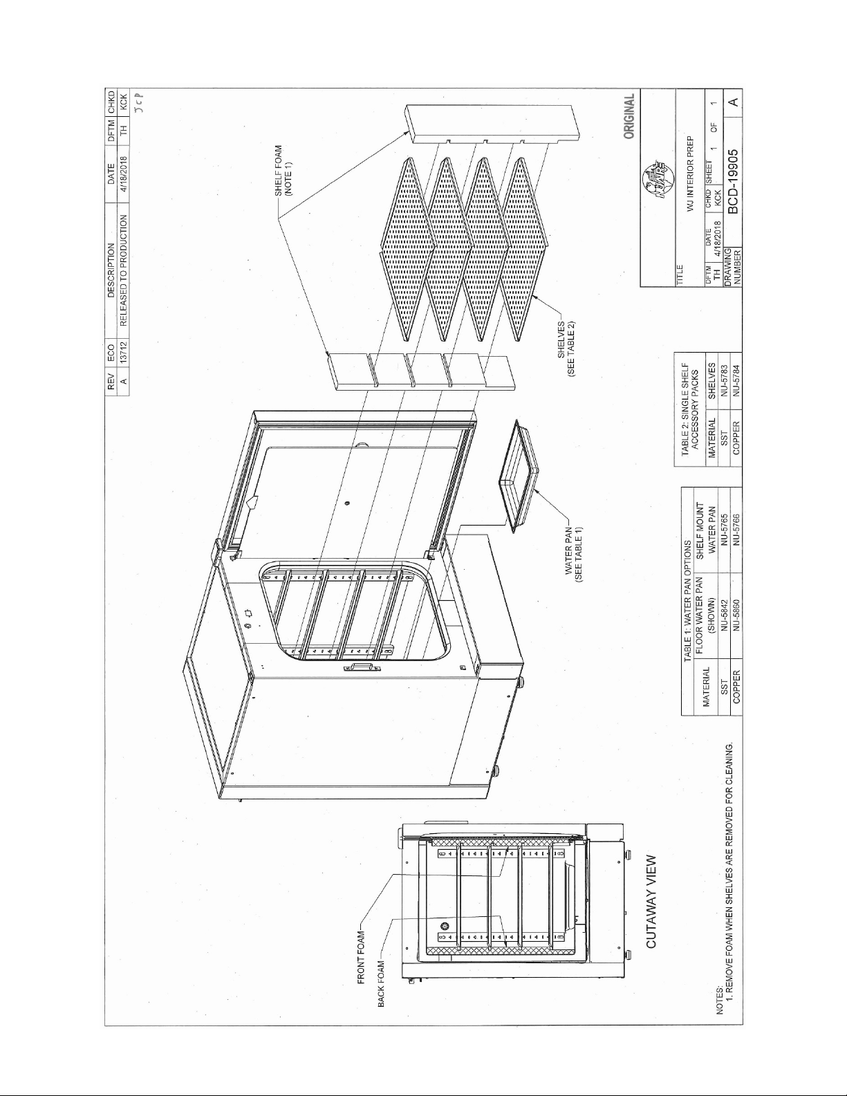
Shelves
Incubator is shipped with the shelves installed. The shelf mounted water pan is also in place that option is ordered NuAire
recommends decontamination all surfaces within the interior chamber, glass door, and outer door with gasket. They can
be wiped down with a disinfectant of 70 percent alcohol or similar non-corrosive antimicrobial agent. Use only
disinfectants that are compatible with the vinyl gasket, the powder coat paint on the outer door and the 304L stainless steel
in the chamber. See BCD-19905
Note: Absolutely no chlorinated or halogen materials are to be used in the chamber.
NOTE: NuAire does not offer any product warranty with respect to cleaning material compatibility. USE AT YOUR
OWN RISK! The information provided above is from raw material suppliers and known general source documents
for use to develop application cleaning SOP’s.
Four (4) shelves are installed in each Incubator. The shelf positions are easily changed by removing the shelf and moving
the horizontal guides to the desired position. If the shelf does not bind or disengage from the horizontal bracket it is
installed correctly. Additional shelves and shelf guides are available.
Water Pan
Place water pan in the center on the bottom of the chamber and fill with Single distilled water no purer than 1 Mega Ohm.
It is recommended to fill the pan to a maximum of about 1/2 inch below the top rim. See Sections 3.1 and 8.2 for more
specifications and operational details regarding proper maintenance instruction regarding the water.
OM0253 Page 12 of 53
Rev 6 November/2018
Page 13
OM0253 Page 13 of 53
Rev 6 November/2018
Page 14
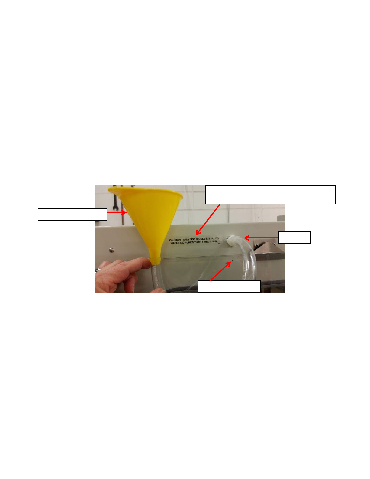
7.4 Electrical
CAUTION: ONLY USE SINGLE DISTILLED
WATER NO PURER THAN 1 MEGA OHM.
Safety Overflow Port
Hose Funnel Assembly
Fill port
The electrical supply circuit to the Incubator must conform to all national and local electrical codes.
Consult the serial-data plate, located at the front of the right side of the Incubator, for voltage, cycle, phase, and ampere
requirements before making connection. Plug the power cord securely into a grounded power source. VOLTAGE SHOULD
NOT VARY MORE THAN 10% FROM SERIAL PLATE RATINGS. Have a qualified technician check with the power source with a
properly rated volt meter if needed. A separate branch circuit is recommended to prevent possible loss of product due to
overloading or failure of other equipment on the same circuit. A SURGE PROTECTOR IS STRONGLY RECOMMENDED to
avoid power-related faults.
7.5 Precaution for Incubator Filling
To prepare the Incubator for filling, turn on main power switch located on back panel. The “Maintenance Required”
notification will show in the main screen indicating that the Jacket requires water.
CAUTION: Only turn the Incubator on when you are ready to fill the water jacket.
7.6 Filling & Draining the Water-Jacket
The fill port plug is located on the front top left side behind the door. Install the fill port fitting. Place the tubing over the
adapter and connect the other end to either a funnel or serrated tap. Use single distilled water, NO PURER THAN
1 MEGA OHM. Fill the Water Jacket until the "Maintenance Required" indicator in the display screen turns off. Add an
additional 3 to 4 liters of water, remove the tube adapter, and replace with the fill port plug.
Be sure to position and level the Incubator as desired before filling with water.
The Water Jacket requires no anti-bacterial agents. The Incubator already incorporates a copper tube producing copper
sulfate which eliminates bacterial growth within the water jacket. ABSOLUTELY NO CHLORINATED OR HALOGEN
MATERIALS ARE TO BE USED IN THE WATER JACKET.
A safety overfill port is located next to the fill port plug so if overfill does occur, the water will be relieved through the port.
This can be drained from the drain plug located on the bottom front under the valance. The drain uses a ball valve to
control the drain water. If the valve stem is perpendicular to the port in the valve it is closed. Turn it clockwise to open. A
white safety plug must be removed prior to draining located on the bottom of the ball valve. It also insures no leakage will
occur.
OM0253 Page 14 of 53
Rev 6 November/2018
CAUTION
DO NOT OVERFILL!
Page 15
7.7 Air Inlet Connection
CAUTION
!
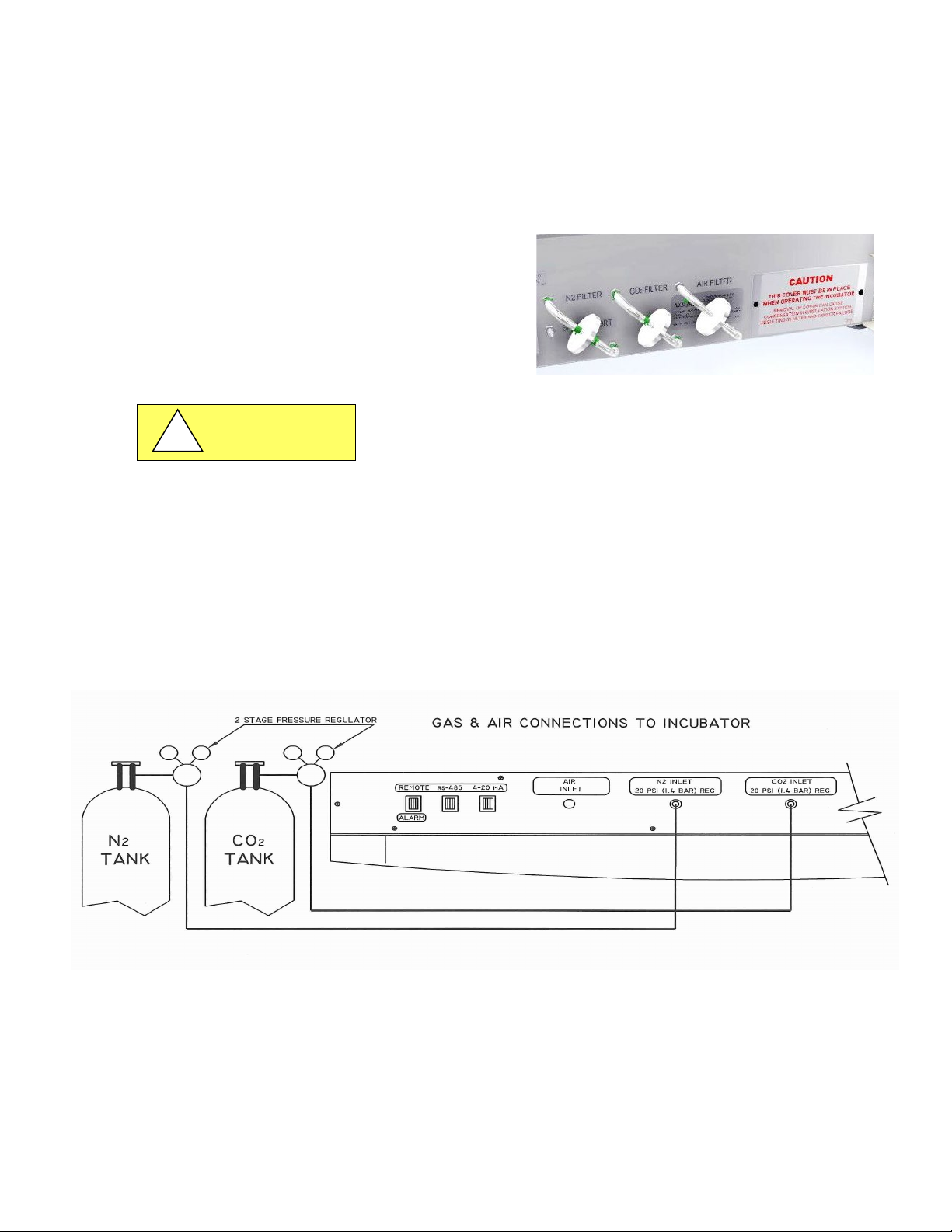
The air inlet and filter are installed at the Factory. The filter has flexible hose that attaches to bulkhead fittings in the
bottom of the front panel and can be found under the valance that is beneath the door. One 50mm polypropylene .3micron HEPA filter is connected to the hoses. The filter is labeled “Air filter”. To remove the valance the outer door must
be open. Reach in under the valance and lift it to remove. See BCD-18476. The air inlet on the back of the incubator is
connected to the filter by a hose at the factory and does not require installation.
CAUTION: This is a free air supply. DO NOT connect to a pressurized air source.
7.8 CO2 / N2 Gas Supply Setup
7.8.1 Gas and Air supply HEPA filtering is installed at the
Factory on the front of the incubator as illustrated
in the picture.
Each incubator is equipped with the filters required
for the control systems available on that model.
• CO
Pressure to the Invitrocell is rated at 20 PSIG or 1.4 BAR.
2/N2
Do not exceed 25 PSIG or 1.8 BAR to avoid damaging the incubator.
• CO
of medical grade is recommended.
2/N2
• A two-stage pressure regulator, Linde #19590 (NU-1564)
or equal is recommended.
• DO NOT USE a single stage regulator.
7.8.2 CO
/ N2 Gas Supply Tubing Connections
2
Included with this unit and for all models of the 5800 series is (1) six foot (2 m) of vinyl tube.
It connects between the low pressure side of the 2 stage regulator at the CO
INLET (as shown in the following Figure). Next, secure each connection with the clamps supplied.
CO
2
supply and incubator fitting labeled
2
On Model NU-8631 there is a second six foot (2 m) of vinyl tube. It connects between the low pressure side of the 2
stage regulator at the N
supply gas and incubator fitting labeled N2 INLET. Next, secure each connection with the
2
clamps supplied.
Figure illustrating CO
and N2 gas supply connections
2
OM0253 Page 15 of 53
Rev 6 November/2018
Page 16
7.8.3 CO2/ N2 Supply
CAUTION
!
CAUTION
!
• CO
/ N2 of medical grade is recommended.
2
• A two-stage pressure regulator, Linde # 19590, or equal, is recommended.
• DO NOT USE a single stage regulator.
It will not give a stable output at 20 psi and exposes the Incubator to the gas cylinder pressure.
• High concentrations of CO
gas can cause asphyxiation!
2
• Install Incubator in a well-ventilated area.
• Gas Supply pressure to the Invitrocell is rated at 20psi (1.4 bar).
• Do not exceed 25psi (1.8 bar) or damage to the incubator may occur.
This Incubator is designed to be operated with CO
Connecting a flammable or toxic gas can result in a hazardous condition.
Gases other than CO
CO
gas cylinders have a UN1013 label on the cylinder and are equipped with a CGA 320 outlet valve.
2
/ N2 should not be connected to this equipment.
2
Check the gas cylinder for the proper identification labels.
Do not use CO
A siphon tube is used to extract liquid CO
gas cylinders equipped with siphon tubes.
2
from the cylinder which can damage the pressure regulator.
2
Consult with your gas supplier to ensure that the CO
7.8.4 CO
/ N2 Pressure Regulators
2
• The regulator’s high-pressure stage direct from the supply cylinder must have a range of from 0 to 2000 PSI or
0 to 140 BAR. This gauge indicates actual tank pressure.
• The low-pressure stage should have a range of 0 to 30 PSI or 0 to 2 BAR (100 PSI or 6 BARS maximum). This
gauge will indicate the actual CO2/N
• Some single stage CO
All NuAire Incubators use CO
pressure regulators have two gauges. USE A TWO-STAGE REGULATOR.
2/N2
in such quantities that precise metering of CO2/N2input pressure is important for
2/N2
2
maximum performance.
To connect the regulator:
1. Open the CO
cylinder slightly, for an instant (this is termed “cracking the valve.”)
2
This will blow out dust or dirt that may have collected in the valve outlet.
BE SURE to keep your face away from the valve outlet to protect your eyes from dust or dirt.
2. Make sure the regulator pressure-adjusting screw is released by turning it counterclockwise
until it turns freely.
3. Attach the regulator to the cylinder valve and tighten the connection nut with a wrench.
BE SURE DISC SEAL IS IN PLACE BEFORE MAKING CONNECTION.
7.8.5 CO
/ N2 Supply Adjustment
2
With the regulator OFF (i.e. fully counterclockwise), open the cylinder valve slowly usually 1 to 2 turns is sufficient.
NEVER STAND IN FRONT OR BEHIND THE REGULATOR WHEN
OPENING THE VALVE. ALWAYS STAND TO ONE SIDE.
The cylinder tank pressure should read: 700 to 800 PSI (48 to 55 BAR) for CO
more or less depending on the temperature of the cylinder.
for N
2
Next turn each regulator's pressure adjusting knob clockwise until the low-pressure gauge reads 20 PSI or 1.4 BAR.
Both gas connections are now complete.
Note: OSHA requires the CO
tanks to be physically restrained (i.e. via chained to wall)
2
to prevent accidental damage to cylinder.
7.8.6 Checking the Connections
The connections can be checked for leakage by brushing a small amount of soapy water on each one.
Observe to see if any bubbles are blown. If not the connection is secured properly.
If it is, the cause of the leaking needs to be determined, (i.e. loose clamp or damaged hose) and corrected.
gas only.
2
cylinder does not contain a siphon tube.
2
pressure to the Incubator.
or 2550 to 2650 PSI (176 to 183 BAR)
2
OM0253 Page 16 of 53
Rev 6 November/2018
Page 17
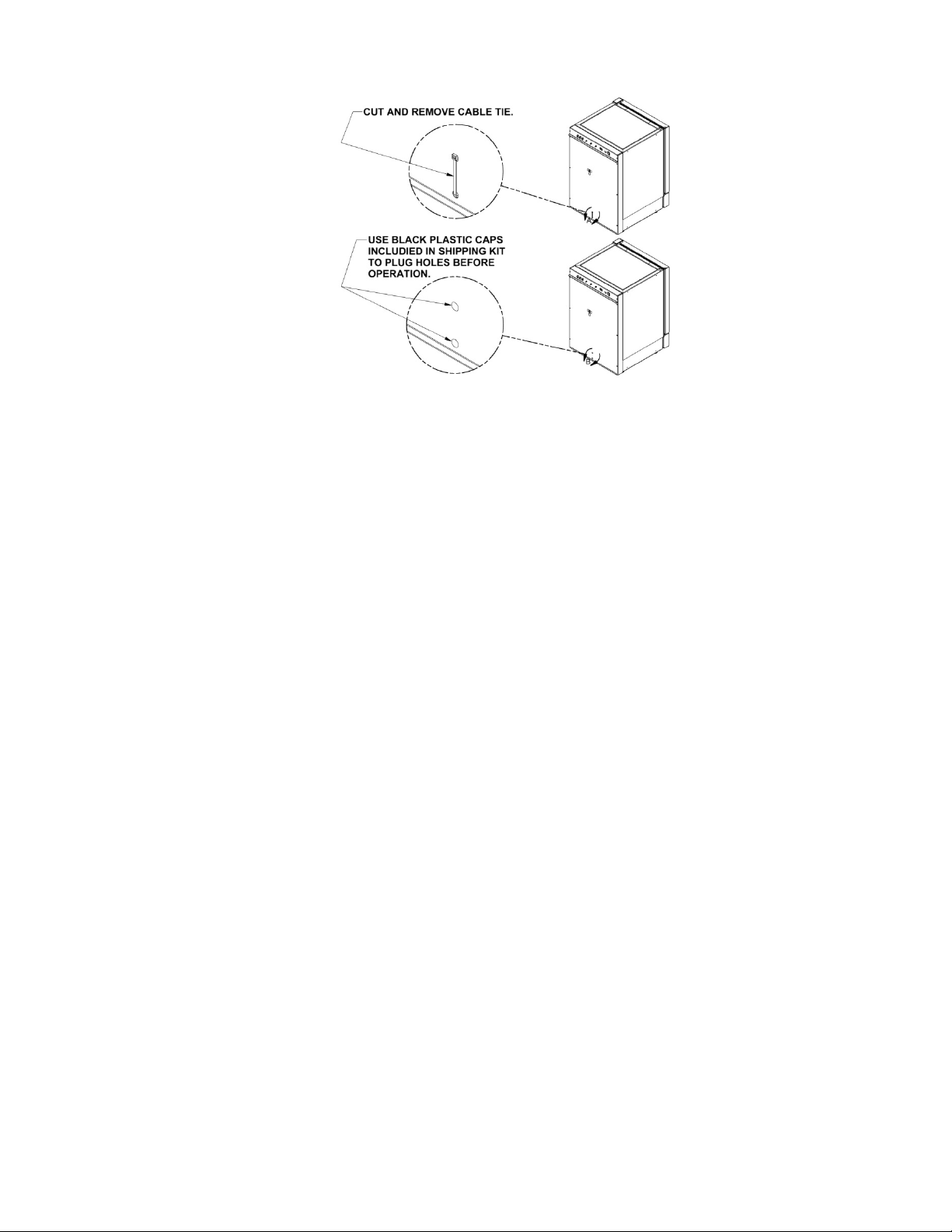
7.9 Removing the cable ties used to secure the Air pump for shipping:
7.10 Setting up the access port:
When utilizing the access port do not block or restrict the relief holes in the center of the port plug. Blocking this venting
can cause performance issues for the incubator. Cut slits or new holes in the vented plug to make passage for cables or
other items requiring access to the chamber if needed.
7.11 Correct Installation
When the Incubator is installed correctly connected to the power source it is rated for gas connections made properly,
the water pan filled, the shelves in place, and the unit is leveled. Read section 8 and follow all instructions for setting set
points at the desired value. Then calibrate the Incubator control systems as explained in section 9. If the Incubator is
installed and calibrated correctly it will meet the performance specs listed in section 3.2.
7.12 Reversing Incubator Hinges
Reversing the incubator hinges from the right to the left side SEE PTB0236 for instructions.
This requires disassembly of the incubator and should be done by a qualified service technician.
OM0253 Page 17 of 53
Rev 6 November/2018
Page 18
8.0 Water Jacket Operation
564
191
ATTENTION ACCOMPANY'S
SYMBOL
POTENTIAL ELECTRICAL
PERSON TO ACCESS
188
HOT SURFACE
!
CAUTION
!
Safety alert symbol indicates potentially hazardous
Situation which, if not avoided, may result in minor
Or Moderate injury.
CAUTION: A qualified technician who is familiar with the proper maintenance procedures required for this equipment,
as well as repair, must perform all maintenance actions on this equipment.
The Incubator is designed to provide a sterile, constant temperature, constant CO
for optimum growth of tissue cell cultures and other organisms requiring this precise environment. To operate the Incubator
properly, the following parameters must be reviewed, carefully set, and/or prepared.
8.1 Sterility
The chamber environment is not selective. The growth environment is applied equally to all microorganisms (specimens
and contaminates) within the chamber. Therefore, before placing any cultures in the Incubator, the shelves and sidewall
top plenums should be sterilized. The interior sidewalls, top, bottom, door, as well as the gasket should be wiped clean
with a 70% solution of isopropyl alcohol or other disinfectant compatible with the chamber construction, to remove any
contamination. Use mild detergent to clean the exterior of the Incubator.
NOTE: NuAire does not offer any product warranty with respect to cleaning material compatibility. USE AT YOUR
OWN RISK! The information provided above is from raw material suppliers and known general source documents
for use to develop application cleaning SOP’s.
INFORMATION OR IMPORTANT
HAZARD ONLY QUALIFIED
BURN POTENTIAL
level and naturally humidified atmosphere
2
8.2 Humidity
Water Pan available on all Models
Humidification of the Incubator chamber is achieved through the process of water evaporation (vapor water pressure) from
a stainless steel water pan placed on the bottom of the chamber. Materials of different thermal resistance (e.g., glass,
plastic) do not offer sufficient thermal recovery and are not recommended for water pan usage. Although some metals
offer better thermal coefficients than stainless steel, dissimilar metals cause electrolysis in the acid atmosphere (carbonic
acid) and should never be used, or placed within the chamber.
Use only distilled or mineral-free water, no purer than 1 mega ohm, in the stainless steel pan. The water should be
changed at least once a week. FLOODING THE BOTTOM OF THE INCUBATOR IS NOT RECOMMENDED since it is difficult to
change the water weekly and almost always necessitates the use of chemicals, which are not recommended and may
damage the stainless steel. Also, it promotes condensation on the inner walls because it steals the natural convection, heat
flow through the inner chamber and condensation points occur.
NOTE: ABSOLUTELY NO CHLORINATED OR HALOGEN MATERIALS ARE TO BE USED IN THE CHAMBER.
Humidity Recovery: Using the water pan supplied with the incubator and with a 5.0% CO₂ set point.
NU-8631: Recovery after a door opening is directly dependent on the O₂ set point and ambient RH.
The lower each of these factors is the longer the recovery time.
Contamination in the water pan may be avoided by adding a small amount of copper sulfate to the water pan after each
Incubator decontamination.
NOTE: Please contact the copper sulfate manufacturer to determine the proper amount of copper sulfate
that should be added to the water pan.
OM0253 Page 18 of 53
Rev 6 November/2018
Page 19
Condensation on the glass door / front chamber or in the back of the chamber indicates that the door heater cycle requires
calibration (see section 9.2). The fresh airflow that the air pump delivers to the chamber has been preset at the factory. If
condensation starts forming on the sides or back wall in the chamber, the number and length of air injections into the chamber can
be increased. (See section 8.8.1.2 for instructions.) To alleviate the condensation, increase the airflow. To increase RH in the
chamber reduce the airflow. If airflow is decreased, some condensation may be unavoidable. The port plug with breather hole must
be used on the side port.
NOTE: DO NOT SEAL OR RESTRICT THE OPENING IN THE PORT PLUG.
THIS IS A PRESSURE RELIEF FOR THE CHAMBER.
8.3 Control System Introduction
The NuAire Incubator Control Electronics system is designed to serve the control requirements of the Incubator chamber.
Temperature, CO
conditions for culture growth within a chamber. Operator input is coordinated through the NuTouch LCD keypad and status
displays.
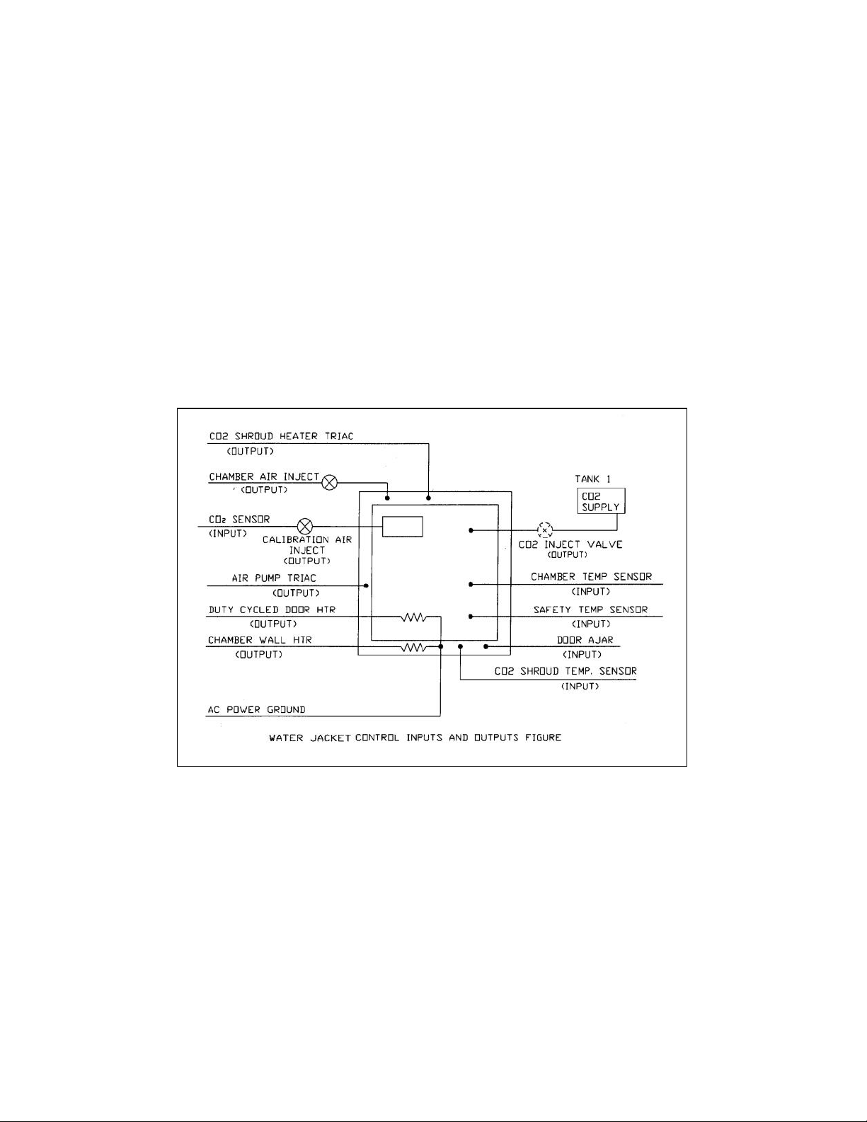
Figure 1 shows the various inputs and outputs of the system.
levels in all models and O2 in available models are controlled by preset values to provide the optimum
2
OM0253 Page 19 of 53
Rev 6 November/2018
Page 20
8.3.1 Chamber control in a single electronic package.
Button Description
Action when touched
Control system description
(i.e.….TEMP or CO2)
Brings a pop up screen that describes the control system
that was touched
Goes to the Environmental Set Point Screen
the password function is enabled)
Goes to “System Settings” Screen for
access to more menus
Date & time display
Goes to screen for adjusting time and date
Save
Cancel
Exit
Close
Cancel
Exit
CancelNextStart
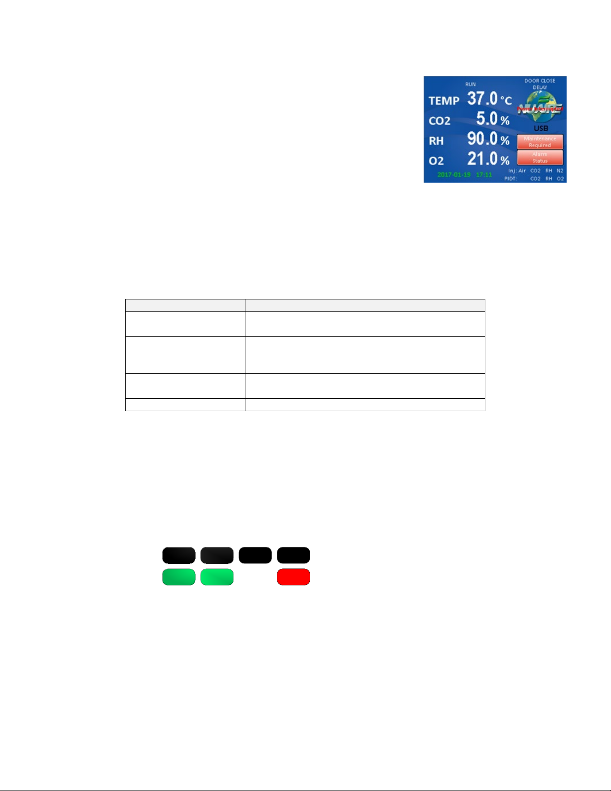
8.3.2 Enhanced information presentation on a NuTouch LCD
Main Screen Continuously displays:
• Measured Chamber Temperature
• Measured CO
• Measured O
%
2
% in available models
2
• Current Screen ID “MAIN SCREEN”
• A mode status indicator (RUN, STANDBY or Power loss Recovery)
• Door ajar status displays when door is ajar
• Door Closed status displays when door is closed
and flashes during the post door close delay time.
• NuAire Logo button Leads to the System settings
menu when pressed
• Date and Time
• Air, CO
• PIDT: CO
& O2 inject indicators show when gas or RH is injecting.
2
& O2 indicate that the system showing is in Post Inject Delay Time.
2
• An Alarm Status Menu
• Maintenance Required displayed
8.3.3 Active buttons on the MAIN SCREEN:
Measured value of
each control system
(Key pad to enter password will pop up if
NuAire Logo
8.3.4 Accessing the Incubator Control Screens
Accessing the many Control screens, performing functions and diagnostic tests, and maneuvering through the
NuTouch LCD menu system is accomplished through the following methods:
• Touching a “graphic” Icon like the NuAire Logo in the Main Screen which access the System Settings menu,
or lead you to an Enter Password screen when a password has been established.
• Touching a “Button function” button command that is visible on the screen.
The button will have text in it indication the function you are about to perform.
The following buttons are used on all models:
An explanation of these buttons is as follows:
Save – This command saves the changes you have made and returns you to the calling screen or, in some
cases, back to the main menu.
Exit – This command exits you from the current screen and returns you to the calling screen.
Close – The command causes the current screen to be removed and returns back to the calling screen.
Cancel – This command will cancel the changes you have made, and in some circumstances, cancels the
“set of requests” that you have entered and returns you back to the calling screen.
(e.g., cancel in the middle of the Decon screen setup returns you to the calling screen)
Start – This command causes a main event to begin (e.g. Decon Cycle).
OM0253 Page 20 of 53
Rev 6 November/2018
Page 21

Next – This command causes another step (screen), in a list of steps (screens) to be displayed
(e.g., Decon cycles and some CO
calibration screens).
2
Back – This command returns you to the previous screen.
Decon – This command begins the Decon sequence.
• Touching a “Text” button command. The text or numerical value will be in blue indicating that is a link
similar to the computer or on the internet. The system settings menu screen shown below is a good
example of both the Text commands and Button commands:
Note: The Main Screen is the one exception for the above described buttons.
The green clock text is and is a link to adjusting the time.
The large white Control system measured values are also a “second” link to the “Environmental Set-
Points” menu and the control system descriptions are a link to system description pop up screens
when touched.
8.3.5 Functioning accessed from the System Settings screen:
The “System Settings” menu screen can be accessed from the “Main Screen” by touching the NUAIRE logo:
Environmental Set-Points: Allows adjustment of Temperature, CO
Note: You can also access the Environmental set points by touching any
control system numerical value in the MAIN SCREEN.
Performance Monitor: Views a function’s Set-Point and Measured values over the last seven days.
Service Settings: Protected by the password 9876, it facilitates Calibrations, Option settings,
and access to Diagnostics.
System Information: Views the units Model Number, Serial Number, Control board assembly (CCBA)
Software Revision and the Display board assembly (LCBA) Software Revision.
Display Settings: Brightness: Allows adjustment of the screen brightness.
Slide right to increase / left to decrease
Calibrate: Press button to access screen calibration - follow screen prompts /
target symbols.
Save: Remember to press the “Save” button after making changes or
calibrating the screen. They will be lost if “Cancel” is pressed to exit
the screen.
Set Password: A 4 digit password can be set and will protect access to Environmental Set points,
running Decon cycles, and changing the password. See section 8.3.7 for instructions
to set the User Password.
System Settings Screen
, and Door heater power level settings.
2
OM0253 Page 21 of 53
Rev 6 November/2018
Page 22
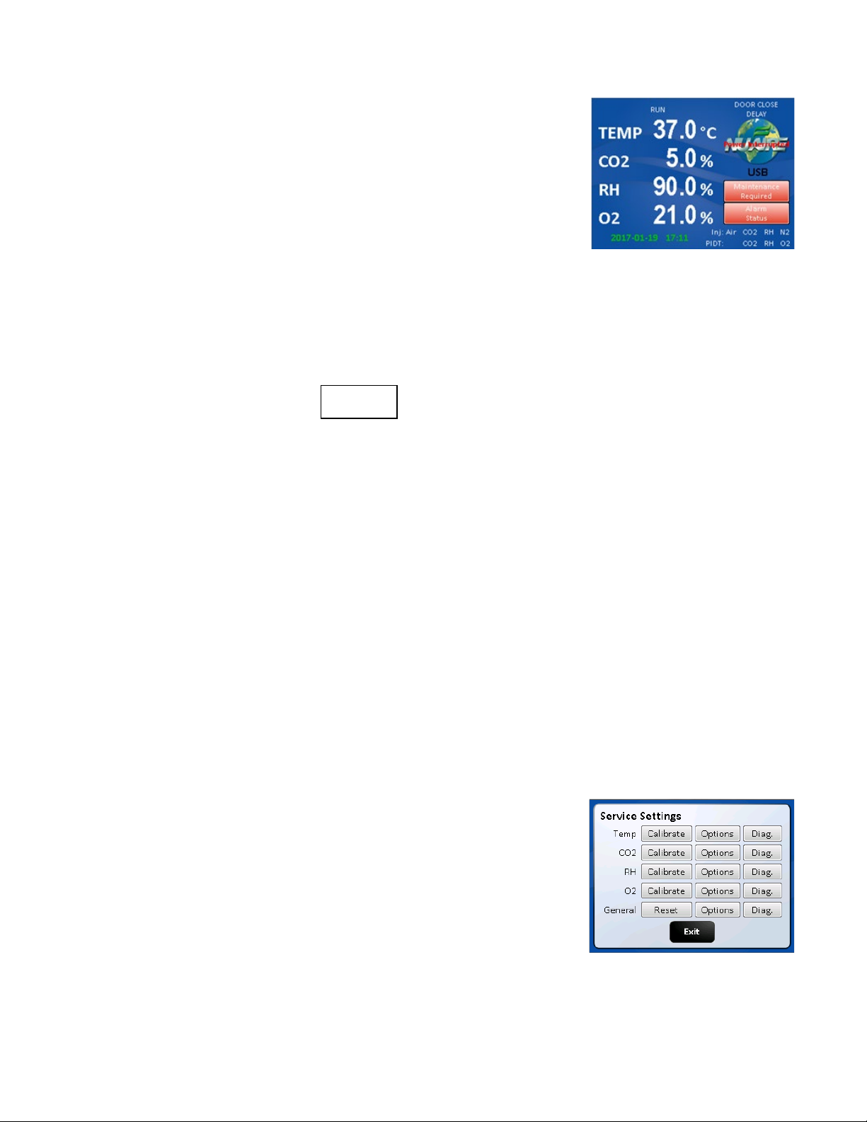
8.3.6 Automatic notification of abnormal situations (See Section 11 for details)
9 8 7 6
The red “Alarm Status” text message (button) will appear on the Main
Screen to indicate a fault within the Incubator system. An audible
alarm is also heard. The audible alarm is on for 10 seconds at the beginning
of an alarm condition and thereafter, it will be on 1 second every 30
seconds.
By depressing (touching) the Alarm Status text on the Main Screen, you now
reach the Incubator Alarm Status screen which will identify which Incubator
sub-systems are in an alarm state (Temperature, CO
exit the screen or touch any of the sub-system buttons which will give you
more specific information on alarm conditions. See Section 11.0 for more
specifics on alarm conditions.
8.3.7 Password Protection
There are 2 levels of password protection.
1. The permanent numerical password required for accessing the “Service Settings” menu screen.
This screen is accessed by pressing the “Service Settings” text Icon in the “System Settings” menu screen.
The password is and it cannot be changed or deleted.
The functions in the “Service Settings” screen are intended to be used by qualified technicians to calibrate
the control system sensors like Temperature and CO
incubator performance, perform system diagnostics and to Factory or Master reset for returning the
incubator to Default settings.
, or General). You may
2
, adjust optional parameter settings to customize
2
2. A selectable 4 digit numerical password that is entered by the Incubator user to prevent others that are not
authorized to change the Incubator set points (CO
Decon Cycle or changing passwords. The password protection may be initiated by accessing the “Set
Password” menu in the System Settings menu screen. Once initiated, a four digit number must be entered,
then re-entered for verification.
8.3.8 Standard remote communication capability
The NU-8600 & NU-8631 Incubator model series comes equipped with the following remote communication tools:
• USB Output of daily, weekly & monthly performance logs and an event log that indicates when alarms,
door openings and power interruptions occur.
• 4-20 milliamp analog Output
• RS-485 2 way communications
• A USB method of updating the software
8.3.9 Diagnostic and calibration assists.
To access the Service Settings Menu, perform the following steps: NuAire
Logo → Service Settings → 9876 Enter. You are now in the Service Settings
Menu (screen). This screen provides you the capability to review and
analyze numerous Incubator functions including the following:
• Individual analog inputs may be displayed to assist calibration.
• Individual outputs may be forced to an on or off condition.
• Individual digital inputs may be displayed.
• Calibrated and Uncalibrated values are displayed.
• All options may be individually tested.
%, Temp), running conditions of the Incubator, initiate a
2
OM0253 Page 22 of 53
Rev 6 November/2018
Page 23

8.4 NuTouch Display Screen
The system LCD touch screen has the following functions.
8.4.1 Front LCD touch screen Descriptions
The NuTouch LCD allows the user to access a wide variety of unit
configurations and diagnostic menus by touching the NuAire logo icon.
The Main Screen displays:
• Power Interrupted message displayed when power is lost and then
re-connected
• current Calibrated values of control systems that have been enabled
• Current operating mode (run or standby)
• Door Ajar, Alarms, and Maintenance notices
8.4.2 Inject CO
On the bottom right of ‘Main’ screen, “CO
/ O2
2
/ O2” text indicates when the inject valve is open and the gas is flowing
2
into the chamber maintain set point for each of the control systems.
Each text icon appears independently when that System is actively injecting.
8.4.3 Post Inject Delay Time (PIDT)
On the bottom right of the ‘Main” screen just below the inject status icons from 8.4.2, “CO
/ O2” text indicates when
2
these systems are in post inject time after the injection is done.
Each text icon appears independently when that system is in the delay time.
8.4.4 Inject Air Status
On the bottom right of the Main screen “Air” text indicates that fresh air is currently being injected into the chamber.
8.4.5 Door Ajar Status
The door ajar white text message indicates when the inner glass door is not closed and latched; the inner glass door
is open. The door ajar status is a result of the pressure switch (open/closed) located along the top middle of the
front panel. After the door is closed, the text will display “Door Closed Delay” indicating the delay time (60 sec
adjustable).
8.4.6 USB status
The USB status icon appears in the lower right side of the Main screen when a memory stick is placed in the USB port
to the right of the NuTouch display while down loading performance and event history. This icon disappears when
the memory stick is removed from the port.
CAUTION: When a memory stick is placed in the USB port it can interfere with the RS-485 communication output.
The RS-485 communication may have to be restarted after the memory stick is removed from the port.
8.4.7 Power Interruption Notification
Indicates when a power interruption has occurred. This can be from a power outage or just turning off the
incubator. Responding by touching the text will return the Logo button.
8.4.8 Maintenance Required Notice
The Maintenance required notice appears in the middle of the right side of the screen indicating that either the
water jacket needs to be filled or that it is time to check the capsule filter in the Sensor bay. Press the notification
button to bring up the screen that indicates the maintenance that is required.
8.4.9 Alarm Status Notice
The “Alarm Status” button indicates an abnormal status condition.
This text appears just above the AIR CO
status messages (paragraph 8.4.2 and 8.4.3). The “Alarm Status” button and
2
audible alarm indicates the abnormality. A catastrophic temperature control condition will de-energize the safety
relay and cause the chamber to cool below the set point. The unit will resume heating when it has recovered from
the abnormality. See section 8.3.5 and 11.0 for more details on Alarms.
OM0253 Page 23 of 53
Rev 6 November/2018
Page 24

8.5 Rear Component Panel Detail
The rear control panel contains the following functions (see also BDC-15170)
8.5.1 Power Cord
The power cord is 6.5-foot (2 m) in length, type “SVT” molded plug, allowing for long life and easy cleaning.
8.5.2 Circuit Breaker
All control electronics are protected with a circuit breaker that may trip at 110% of load rating, but will trip at 145%
of load rating in less than 2 seconds.
Should the circuit breaker open (pop-out button will appear), merely depress to reset.
8.5.3 N2 Inlet on NU-8631
inlet provides a fitting for vinyl tubing for oxygen control.
The N
2
Be sure to follow the recommended inlet pressure to insure proper flow rates and consistent O
percentage
2
readings.
8.5.4 CO
The CO
Be sure to follow the recommended inlet pressure to insure proper flow rates and consistent CO
Inlet All models
2
inlet provides a fitting for vinyl tubing.
2
percentage
2
readings.
8.5.5 Power Switch
The power switch, located at the top of the rear panel, controls all power to the Incubator.
8.5.6 Standard Communication Interface’s / Alarm
Three receptacle connectors are provided for direct field connection of a computer for 2 way communications and
incubator monitoring/or output to a printer or other device only capable of receiving RS-485 digital information,
dry contact remote alarm indicator, also 4 to 20 mA output to an analog monitoring device or system.
All come standard and ready to use. See section 10 for more detail.
8.5.7 Air Inlet (All Models)
This is a free air supply.
DO NOT CONNECT TO A PRESSURIZED SOURCE.
Air filter is installed at the factory on the front of the unit.
8.6 Front Component Panel
The front component panel contains the following functions. See BCD-18476
8.6.1 N
Supply filter (Available on NU-8631)
2
supply filter is installed at the factory and should be changed following the instructions found in Maintenance
The N
2
Section 10.
8.6.2 CO
Supply Filter
2
The CO
supply filter is installed at the factory and should be changed following the instructions found in
2
Maintenance Section 10.
8.6.3 Air Inlet Filter - All models
The air inlet filter is installed at the factory and should be changed following the instructions found in Maintenance
Section 10. This is a free air supply.
Note: DO NOT CONNECT TO A PRESSURIZED SOURCE.
8.6.4 Chamber sample port
The Sample port is provided for checking the CO
level in the chamber to monitor the calibration the Sensor and
2
determine if it need adjustment. Located in the inner glass door.
OM0253 Page 24 of 53
Rev 6 November/2018
Page 25
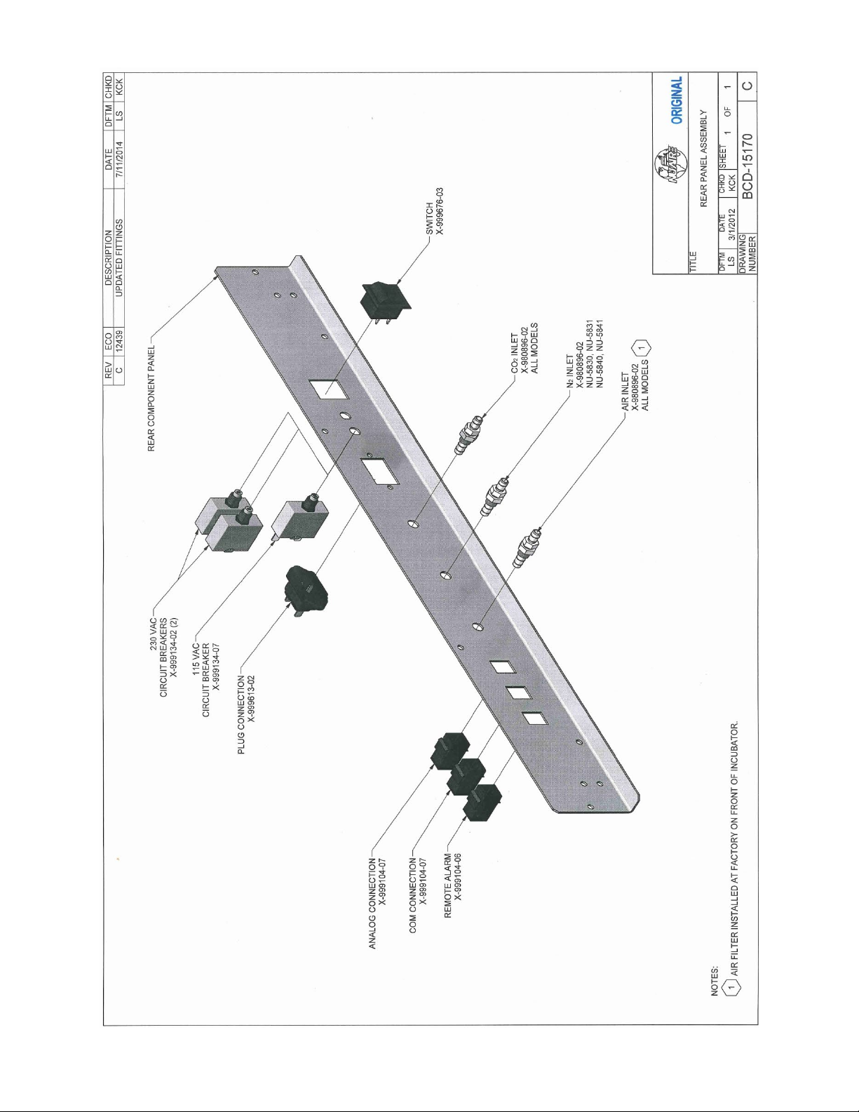
OM0253 Page 25 of 53
Rev 6 November/2018
Page 26
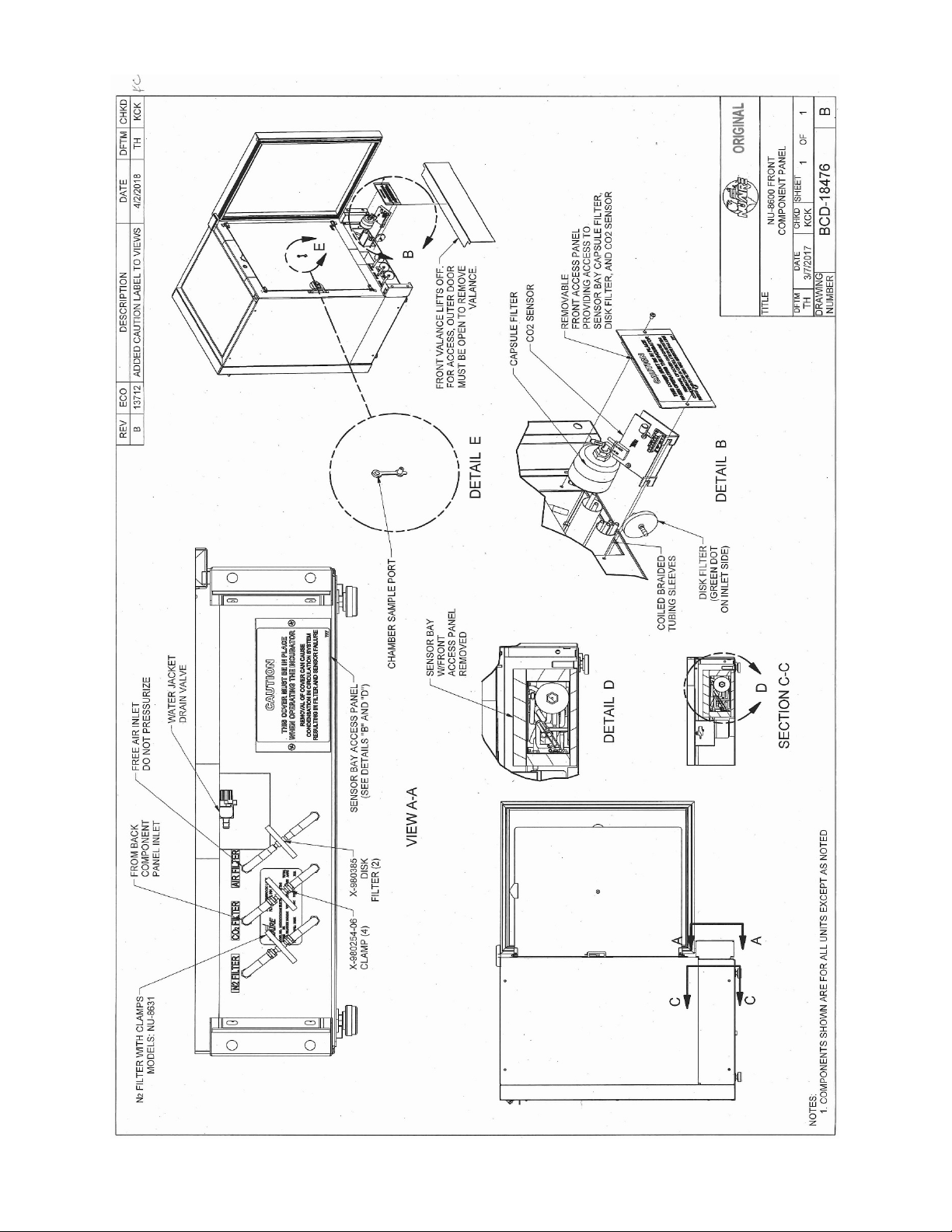
OM0253 Page 26 of 53
Rev 6 November/2018
Page 27

8.7 Run Mode Operator Interactions
8.7.1 THE FIRST TIME THE INCUBATOR IS TURNED ON
• The NuTouch boot up screen appears then shows a screen instructing you to “Read the manual and follow
all instructions to properly install the incubator” Both screens will automatically advance after 5 minutes.
To manually advance:
o Press the exit button then a thank you screen will appear.
o Press the “Continue” button then the unit will go to the “MAIN SCREEN”.
These screens will not show again unless you “MASTER RESET” the incubator control board.
• Setting the Clock
Clock display organization:
YYYY-MM-DD Hr: Min and is displayed in green text in the lower left of the display screen.
• Press the green text and the Time and date adjustment screen appears.
After a power interruption the date and time will flash as follows:
• Green text indicates there was a power interruption but the real time clock remained
powered. Press the flashing text to bring up the “set the clock” screen. If no change is
needed press cancel to go back to the main screen. Otherwise make the required
changes then, press the save button to save the changes and return to the main screen.
• Yellow text indicates the real time clock lost the backup power and the date and time
need to be reset. Press the flashing text to bring up the date/time setting screen Use the
up/down arrows to increase or decrease the highlighted value.
• Use the left/right arrows to move between date and time values that require changing.
• Press “Save” to save the changes you just made or Press “Cancel” to abort the changes and return
to the main screen.
The mode display, on the ‘Main’ screen, is used to identify the mode of chamber operation: either standby or run.
In general, there is no need for operator interaction in "run" mode. However, operator interaction is required when
the incubator is first turned on then to perform calibration functions and address abnormal conditions status. If an
abnormal condition has, or does, exist for a particular parameter, an alarm becomes active and the ‘Alarm Status’
button will appear. This could be a catastrophic alarm condition, which could harm the tissue culture cells. It does
indicate an operational abnormality and should be checked. To acknowledge the abnormality, simply press the
“Alarm Status’ button to view the alarm, to dismiss it press the corresponding alarm’s button. The audio and visual
alarms will then extinguish. If the abnormality still exists, the return after waiting the specified alarm time.
Let the Incubator run normally, and if the alarm doesn't come back on, then everything is normal. If the alarm does
come back on, use the troubleshooting guide to correct the abnormality (see Section 11.0).
8.8 Standby Mode Operator Interactions
The NuAire incubator automatically enters the standby mode when necessary.
There is no action required by the user to enter this mode.
All functions that put the incubator in standby mode automatically start a 10 minute timer.
If the function is not interfaced through the screen on the NuTouch display, the incubator then returns to the MAIN SCREEN
and switches to RUN mode.
8.8.1 Chamber Temperature, CO₂% & O₂% Set- points
8.8.1.1 Accessing the Environmental Set point screen used to manage set
points is done one of two ways:
• Press any control system value displayed in the main
screen.
• Press the NuAire logo then press the Environmental Set
Point text in the Systems Settings screen
8.8.1.2 Pressing the blue numerical value next to the control system that
you intend to change will bring up a number key pad. Punch in the
new value and hit the
“ent” key to leave the key pad and return to the Setpoint screen. You will be asked if you want to save the new set point(s) when you press Exit to leave the set
point screen and return to the Main screen.
Press “Save” to retain the changes.
OM0253 Page 27 of 53
Rev 6 November/2018
Page 28

8.8.1.3 Default Set points
Temperature
37.0 C
All Models
Note 1: A set point of 0 (zero) will put the system into an Idle
level of gas in the chamber.
Note 2: A set point of 21.0% will put the system into an idle
lower O₂ set points.
Automatic maximum
O₂ Adjustment
0.1% to 1.0%
20.7%
1.1% to 3.0%
20.0%
3.1% to 6.0%
19.0%
6.1% to 10.0%
18.0%
10.1% to 15.0%
17.0%
15.1% to 20.0%
16.0%
CO₂ 5.0%
state where it does not control and all alarms are
inhibited. The sensor remains active and reports the
All Models
state where it does not control and all alarms are
inhibited.
O₂ 21.0%
Note 3: O₂ set points below 10% will automatically reduce
the Air Injection Time value to “0”. This stops air
injections that will interfere with achieving these
8.8.1.4 Automatic Adjustment of Post Inject Delay Times when O₂ control system is active
Post inject delays are automatically adjusted according to the O₂ set point to facilitate gas recovery after a
door opening. The value displayed in the option menu will not change but is the basis for a formula in the
software that calculates the new delay time depending on the O₂ set point. As the set point is reduced the
delay times are shortened.
The value of the post inject delay time used is the value that shows in the Options display for that control
system whether it is the default or user selected.
8.8.1.5 When the CO₂ system is active the level of CO₂ inversely affects the O₂ present in the chamber.
The maximum achievable O₂ set point is indicated by the following table.
NU-8631
CO₂ Set Point
OM0253 Page 28 of 53
Rev 6 November/2018
Page 29
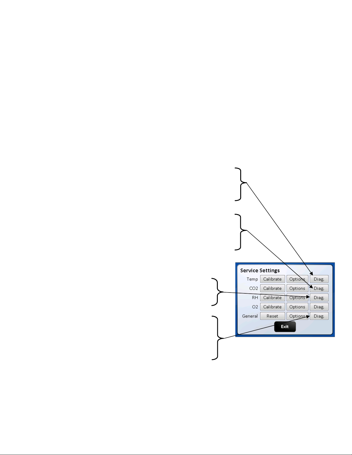
8.9 Diagnostic and Checkout Procedures
The Incubator controller provides general diagnostic facilities:
• Diagnostic mode is intended for factory and field technicians.
• It allows them to turn the controller's output signals (heaters, valves, safety devices etc.) on and off.
• Diagnostics are located in the “Service Settings” menu categorized by the control systems (i.e. Temperature, CO
RH and O
) plus a general category for diagnostics not directly related to the control systems.
2
Press the “Diag” button to access them.
• Each screen and the function buttons in them initiate a 5 minute timer. When the timer runs out, the display will
exit that screen and go back to the Main screen. Manually exiting the diagnostic screen will automatically stop
that timer and return to the Service Settings screen. The function button that was activated will return the
function to the default diagnostic condition at the end of the 5 minute timer. Manually putting the button back to
the default condition will reset and stop the timer.
8.9.1 Diagnostic Mode
To initiate the diagnostic mode, perform the following from the ‘Main’ screen:
• Select the NuAire Logo to enter “System Settings”
• Select “Service Settings” and enter 9876, and then hit enter (ENT)
• In the Service Settings menu, select the “Diagnostics” button for the desired function
Output/Input Diagnostic Parameter Functions
Temperature
1. Safety Relay (on/off)
2. Chamber Temp. Sensor (shows current temp.)
3. Safety Temp. Sensor (shows current temp.)
4. Chamber heater Triac control (0 - 50% - 100 % phase firing)
5. Door Heater Triac control (0 - 50% - 100 % phase firing)
CO
2
1. INACTIVE
2. CO
3. CO
4. CO
5. CO
Sensor (Display current CO2 percentage)
2
Inject Valve /on/off
2
Sensor bay Heater Triac (0 - 50% - 100 % phase firing)
2
Sensor bay Temp. Sensor (Displays current temp.)
2
O
2
Sensor (shows current oxygen level
1. O
2
Inject Valve /on/off
2. N
2
Bypass valve on/off
3. O
2
4. Blocking Solenoid / on/off
General diagnostics
1. Power Supply Regulated +12 VDC (current voltage)
2. Power Supply Regulated -12 VDC (current voltage)
3. Air Inject Solenoid (on/off)
4. Alarm dry contact Relay (NO/C/NC) switch states
5. Air Pump Triac (on/off)
6. Spare AC Triac
(Note: Default values are in bold)
The paragraphs on the following page provide a more complete description of the diagnostics listed above.
The Diagnostic screen is shown to the right of each of the control systems Temperature, CO
& O2 and the General category
2
for your reference. Once entered, the Diagnostics screen will display the calibrated and uncalibrated values of the given
function and all related components.
,
2
OM0253 Page 29 of 53
Rev 6 November/2018
Page 30
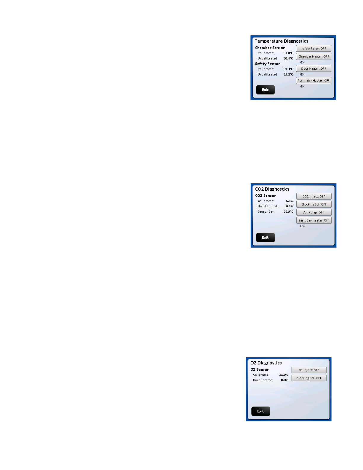
Temperature Control Diagnostics
1. Safety Relay
This function shows the current state of the safety relay.
LCD display will show “On” or “Off” corresponding to the
relay condition. On for closed or set or yes.
2. Chamber Temperature Sensor
This function shows on LCD the current values, calibrated (displayed) and
not calibrated of the temperature sensor controlling the chamber
temperature.
3. Safety Temperature Sensor
This function shows on LCD the current values, calibrated
and not calibrated of the Safety temperature sensor located in the chamber.
4. Chamber Heater Triac Control (0%, 50%, and 100%)
This function allows the jacket heater to be turned on at different percentages 0, 50,100)
5. Door Heater
This function shows on LCD the current state of the door heater. This function also allows the door heater to be
turned on at different percentages (0, 50, and 100 percent). The LCD display will show phase firing percentage
chosen default is 0%.
Control Diagnostics
CO
2
1. CO
Sensor
2
This function shows the current CO
sensor reading both the
2
“Un-Calibrated sensor signal and the Calibrated value shown in the display
screen.
2. CO
Inject Valve / on/off
2
This function shows on LCD the current state of the CO
inject valve. LCD
2
will show “ON” or “OFF” corresponding to the valve condition. On for open
or set or yes.
3. Sensor Bay Heater Triac Condition / on/off
This function shows on LCD the current state of the sensor bay Heater
triac. LCD will show 0, 50, and 100 percent corresponding to the relay
position. The triac can be toggled to each percent of phase firing manually.
4. CO
Sensor Bay Temperature Sensor
2
This function shows on LCD the sensor bay temperature in degrees C.
The Sensor bay is heated to temperature set point +3.5 degrees
5. Air inject Solenoid / on/off
This function shows on LCD the current state of the Air Inject Solenoid.
LCD will show “ON” or “OFF” corresponding to the solenoid position.
Default is off-solenoid activates when the button is touched
6. Air Pump / on/off
Control Diagnostics Functioning
O
2
Sensor
1. O
2
This value displays the current value of the chambers oxygen sensor both
the Calibrated value shown in the display screen and
Un-Calibrated sensor signal.
Inject Valve /on/off :
2. N
2
This function indicates the on/off (default off) state of the N
solenoid valve and allows the activation of it.
Bypass valve on/off: THIS FEATURE IS NOT ACTIVE.
3. O
2
4. Blocking Solenoid /on/off
This function indicates the on/off (default off) state of the Blocking
solenoid valve and allows the activation of it.
OM0253 Page 30 of 53
Rev 6 November/2018
Inject
2
Page 31
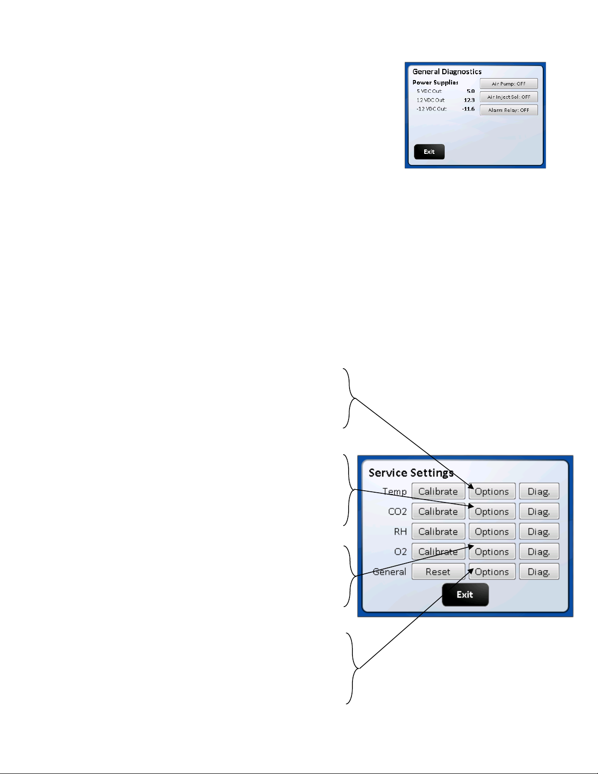
General Control Diagnostics
1. Power Supply Regulated +12 VDC
This function will display on the LCD screen the current value (+12.xx) of
the regulated +12 VDC power supply.
2. Power Supply Regulated – 12VDC
This function will display on the LED screen the current value (-12xx)
of the regulated -12VDC power supply.
3. Power Supply Regulated +5 VDC
This function will display on LCD screen the current value (+5.00) of the
regulated +5 VDC power supply.
4. Chamber Air Inject Solenoid
This function shows on LCD the current state of the Air Inject Solenoid.
LCD will show “ON” or “OFF” corresponding to the solenoid position.
Default is off-solenoid activates when the button is touched
5. Remote Alarm Relay
This function shows on LCD the current state of the remote alarm relay. The LCD display will show “ON” or “OFF”
corresponding to the relay condition and its Normally Open (NO0 pair of contacts
6. Air Pump Triac
This function shows on LCD the current state of the Air Pump Triac. LCD will show “ON” or “OFF” corresponding to
the relay position. The triac can be manually turned On and Off.
Option Configuration Parameters
Format: Option (Default, Minimum/Maximum)
All the options for the NU-8600 & NU-8631 Incubator use this same format. The default is set at the factory and can be
restored in the field with a Master or a Factory reset command. On the following pages, there is a short description of
each Option with its Default/Minimum/Maximum setting, followed by a more detailed description.
Temperature
1. Maximum Above Set Point (1.0°, .1/10.0)
2. Temp Low Time Out Timer (360 minutes, 0/420)
3. Minimum Below Set Point (0.5°, .1/10.0)
4. Temp Sensor Differential (6.0°, 0/10.0)
5. Recovery Delay Time (60 seconds, 0/120)
CO
2
1. System Enable (On, On/Off) (in Settings Screen)
2. Maximum Above Set Point (1.0%, .1/10.0)
3. CO
Low Time Out Timer (10 minutes, 0/240)
2
4. Minimum Below Set Point (0.5%, .1/10.0)
5. Post Inject Delay Time (PIDT) (60 seconds, 0/250)
O
2
1. System Enable (On, On/Off) (in Settings Screen)
2. Maximum above Set Point (1.0 %, 0.0/10.0)
3. O₂ Time out timer (30 minutes, 0/300)
4. Minimum below Set Point (1.0 %, .1/10)
5. N₂ Post Inject Delay time (PIDT) (30 seconds, 0/300)
General
1. Door Close Delay Time (60 seconds, 0/300)
2. Air Inject Time (5 seconds, 0/100)
3. Air Inject Cycle Time (1 minute, 0/120)
4. Digital Output Interval (0 minutes, 0/120)
5. Door Ajar Alarm Delay (5 minutes, 1/60)
6. Settings (Text in top left side of screen)
Note: Selecting any of the Option title texts will open a brief description of that option’s functions.
OM0253 Page 31 of 53
Rev 6 November/2018
Page 32

Default values are in bold
The following paragraphs provide a more complete description of the Optional configuration parameters listed above.
Temperature
1. Maximum Above Set point
This value determines the maximum deviation, measured in (°C) that the chamber is permitted to rise above set
point, once it is reached before an alarm condition is declared. An alarm condition will cause the chamber to enter
a safe condition where no power is enabled to any of the system output controls until the situation is rectified.
2. Temp Time Out
This value determines the time, in minutes, for the temperature to achieve set point. If the temperature doesn't
get to within 0.2° of set point within this time period, an alarm condition is declared.
3. Minimum Below Set point
This value determines the maximum deviation, measured in (°C) that the chamber is permitted to fall below set
point, once it is reached before an alarm condition is declared. CO2 injections are stopped, and air is injected for
15 minutes incase CO2 was not being detected by the sensor. This alarm can be cleared through the alarm screens
or by opening the inner door.
4. Temp Sensor Differential
This value specifies a maximum differential, measured in temperature (°C) that the two temperature sensors may
deviate from one another, or from the last read value. If this differential is exceeded, a warning LED is shown on
the running chamber. If multiple sensors fail to read within the specified limits, an alarm condition is declared. An
alarm condition will cause the chamber to enter a safe condition where no power is enabled to any of the system
output controls until the situation is rectified.
5. Recovery Delay Time
This value determines the time, in seconds, to turn off the chamber heaters in half-degree increments during a
temperature recovery cycle. The delay time is required to prevent temperature overshoot of the control set point.
CO
2
1. CO₂ System Enable (Enabled/disabled) is located in the bottom right of the screen
This function will enable or disable the CO₂ system. If the system is Enabled it will be displayed in the MAIN
screen. If it is disabled it will not be displayed in the Main or Option/Settings screen for the CO₂ system:
System Enabled (with check mark) means the System is enabled
System Enabled (without check mark) indicates that the system is disabled
2. Maximum Above Set point
This value determines the maximum deviation, measured in (%) that the chamber is permitted to rise above set-
point, once it is reached before an alarm condition is declared.
3. CO
This value determines the time, in minutes, for the CO
Time Out Timer
2
percentage to achieve set point. If the CO2 percentage
2
doesn't get to within its lower limit of set point within this time period an alarm condition is declared
4. Minimum Below Set Point
This Function gives the ability to set the value in percent CO₂ below set point that starts the CO₂ time out timer
described in item 2.
5. Post Inject Delay Time
This value specifies the time, in seconds, for an injection of CO
to be measurable at the sensor. When CO2 is
2
injected into the chamber, the system delays until this time period has elapsed before making a new control
decision. In this manner, diffusion induced delays will not cause the CO
system to overshoot the control set point.
2
O₂
1. System Enable (Enabled/disabled) on model NU-8631
OM0253 Page 32 of 53
Rev 6 November/2018
Page 33

Is located in the bottom right of the screen
This function will enable or disable the O₂ system. If the system is Enabled it will be displayed in the MAIN screen.
If it is disabled it will not be displayed in the Main or Option/Settings screen for the O₂ system:
System Enabled (with check mark) means the System is enabled
System Enabled (without check mark) indicates that the system is disabled
Note: System is disabled on all other models
2. Maximum Above Set-Point
This value determines the maximum deviation, measured in (%) that the chamber is permitted to rise above set point, once it is reached before an alarm condition is declared.
3. O₂ Time Out Timer
This value determines the time, in minutes, for the O₂ percentage to achieve set-point. If the O₂ percentage
doesn’t get to within its upper limit of set-point within this time period an alarm condition is declared.
4. Minimum below set-point to Start Alarm Timer
This value determines the limit in percent that starts the Alarm Timer for declaring the alarm.
5. N₂ Post Inject Delay Time
This value specifies the time, in seconds, for an injection of N₂ to be measurable at the sensor. When N₂ is injected
into the chamber, the system delays until this time period has elapsed before making a new control decision. In
this manner, diffusion induced delays do not cause the O₂ system to overshoot the control set-point.
General Options
1. Door Close Delay Time
This value determines the time, in seconds, to increase the door and parameter heater to duty cycle by 10% after
the inner door is closed. Also inhibits gas for the same period.
2. Air Inject Time
This value specifies the time, in seconds, for an injection of air into the chamber
3. Air Inject Cycle Time
This value specifies the amount of time in minutes between each injection of air into the chamber
4. Digital Output Interval
This parameter specifies the frequency, in minutes that performance and set point data is output to a device such
as a printer that is only capable of receiving data. If the frequency is specified as zero, no data will be output.
5. Door Ajar Alarm Delay
Determines how long in minutes the glass door can be open before an alarm is declared.
7. Settings (text located at the top of screen)
Pressing the next button will go to the second page containing the following:
• The Filter Maintenance button to access:
Resetting the change filter notice
Setting time to reminder (24 months/1/48) 0 disables the feature.
View time remaining until current notice is triggered.
• The Clear Password button that clears the 4 digit password that was input through the Set Password
screen.
• Change language Button: Pressing this button brings up a screen with the language choices of English
(default), Spanish, French & German. Pressing the button in that screen of the language desired will
change the user screens to that language.
• Screen Lock button (default Main Screen Unlocked). Pressing this button will change it to “Main screen
Locked” (Lockout = 1). This puts a “Press to unlock” button on the Nuaire Logo in the Main screen. This
feature stops accidental screen changes by brushing the touch screen. You must press and hold (2
seconds) until the message disappears which unlocks the main screen so that you can navigate into; the
System settings, Alarms, Environmental Set Point and Clock Adjustment screens. Pressing the button
again will change the text to “Main Screen Unlocked (Lockout = 0). This removes the “Press to Unlock”
button from the Nuaire Logo and the Main screen goes back to the default condition.
• Power Loss Mode cancel button. Cancels Power loss mode. Only use this if it is certain that there is no
condensation in the circulation system. See Section 10.2 for further details about the Power Loss Mode.
OM0253 Page 33 of 53
Rev 6 November/2018
Page 34
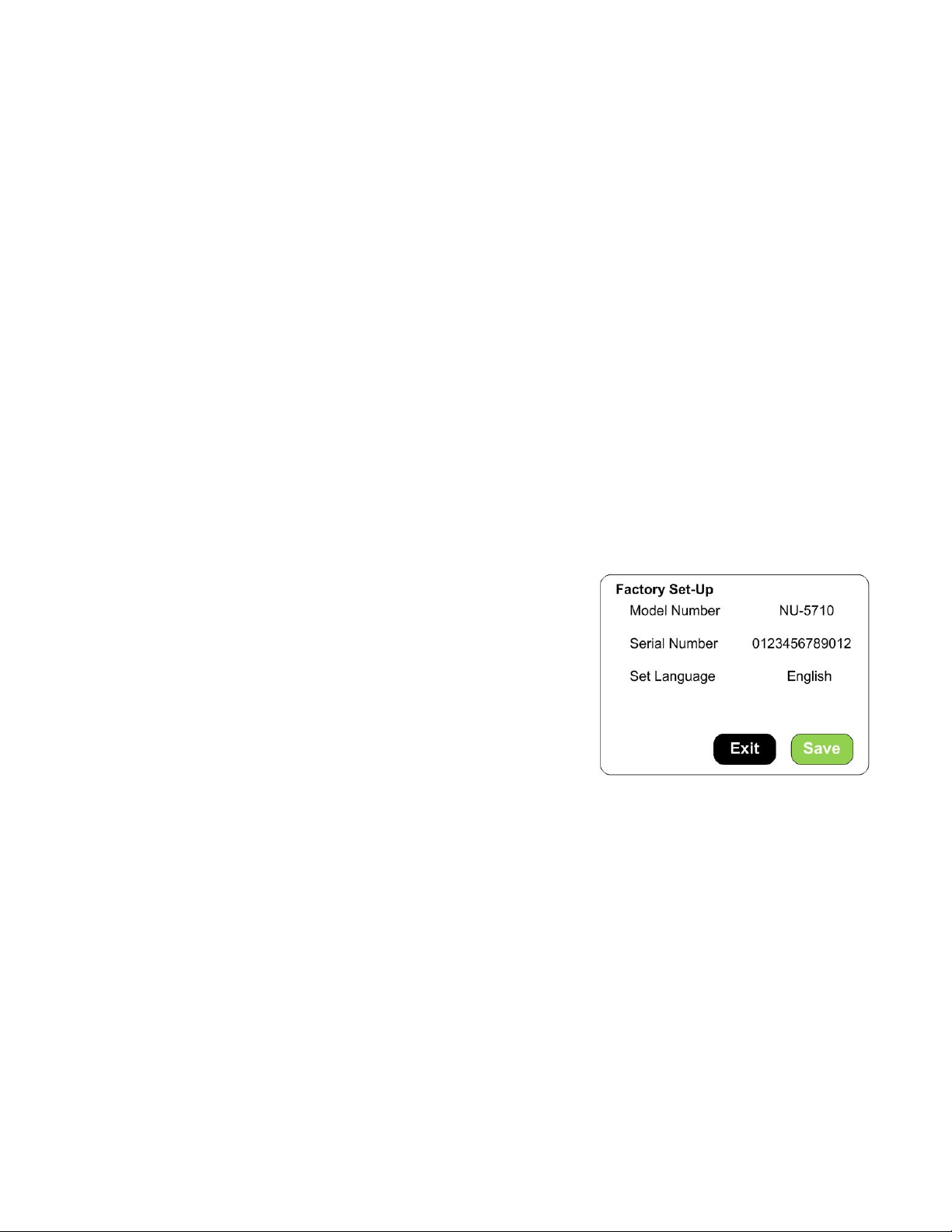
8.10 Resetting the Electronics Software
8.10.1 Factory Reset
The Factory Reset is similar to the Mast Reset. However, it only changes the Options (returned to default settings)
and the environmental set-points (returned to their defaults).
To perform a Factory Reset, you will need to do the following:
NuAire Logo → Service Settings → 9876 Enter → Reset → Factory Reset → Confirm
The Incubator will perform the Factory Reset and return to the Main screen.
8.10.2 Master Reset
The master reset diagnostic function is the last effort to correct operational faults which otherwise cannot be
solved. By reloading the default configuration, the entire memory will be reset and ALL CALIBRATION OFFSETS,
USER PASSWORD, CONFIGURATION OPTIONS WILL BE LOST. All calibrations will need to be performed following a
master reset.
To perform a Master Reset, you will need to do the following:
NuAire Logo →
Service Settings →
9876 Enter →
Reset →
Master Reset →
Confirm
The Incubator will perform the Master Reset then the “Factory Setup” Screen will appear
The Factory Setup screen shows the Model Number, Serial
Number and Language that was chosen for the user screens.
As long as this information is correct you can press Save which
will resave the information displayed in the screen then, take you
to the date and time set screen. If the date and time are correct
you can press exit and go to the MAIN screen. If you press Exit
you will go to the main screen however if there is a power cycle
the incubator will reboot to the Factory set up screen again. All
setup information will show correctly but, you must press save to
boot up into the MAIN screen after a power cycle.. The model
number and the serial number can be verified by comparing them
to the serial number label found down behind the valence under the door. The language defaults to English. It can
be changed any time through the Service Settings/General/Option/settings menu. See section 8.10 for further
instructions.
Note: After performing either Factory or Master Reset remember to turn the incubator off
then on again to ensure that all intended parameters were reset.
OM0253 Page 34 of 53
Rev 6 November/2018
Page 35
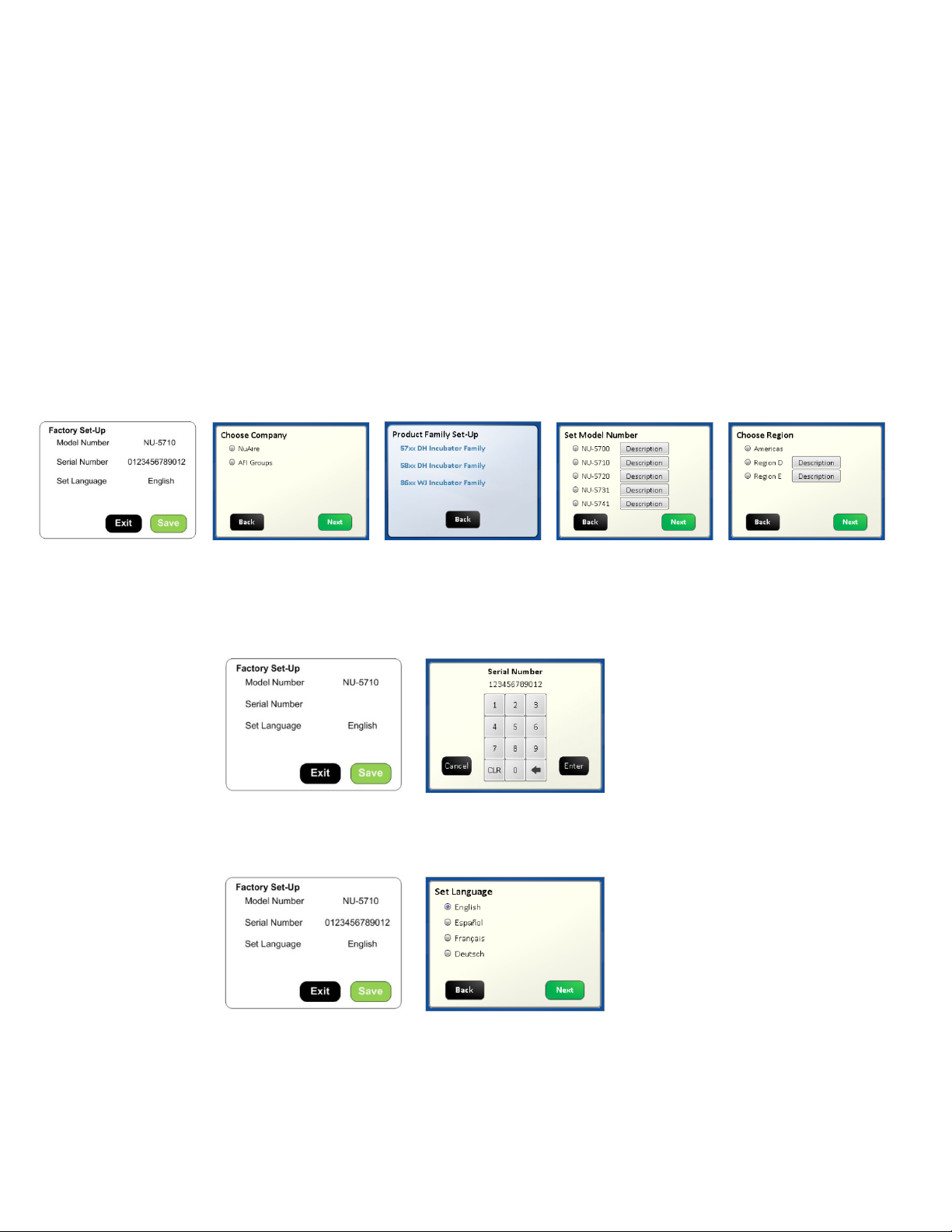
8.10.3 Inputting the Factory settings:
The “Factory Set-up” screen will appear after the master reset. If the Model Number or the Serial Number need to
be re-input for any reason the following steps should be taken:
Setting the model number sets the following function:
• All Nuaire customers will press Nuaire in the “Choose Company” Screen. This will bring up the
Nuaire logo in the main screen.
• Model number NU-8600 and NU-8631 and E or D models
Enables Temperature and CO
Chooses the algorithm suited for low watt heating of the chamber
Supresses the decon button in the “Systems Settings” screen
Loads the model number in the System information screen
• Model numbers NU-5720 through NU-5741 and E or D models
Enables Temperature and CO
Chooses the algorithm suited for high watt heating of the chamber suited for heated Decon cycles.
Activates the heated decon cycle choices in the “Systems Settings” screen
• Touch the “Model Number” text then follow the screen prompts as shown below.
Pressing continue on the choose Region screen will bring you back to the Factory Set-Up screen showing
the Model Number you just entered. Default is NU-5800 if no model number is entered
the only control systems available on this model
2
plus RH and O2 control systems as available on the various models
2
• Touch the Serial Number text then enter the 12 digit serial number which can be found on the serial
number label located behind the valance under the sample port. Press the ENT button on the key pad
screen and you will return to the Factory Set-Up screen showing the serial number you just entered.
Default is blank if no number is entered.
• Touch the Set Language text then touch the save button. This sets the language on all of the user screens.
The language in the Service Settings menu /screen will remain in English. English is default language if
none is chosen. Touch the green save button to exit the factory screen.
• The final change that is requested is the clock. It should not have been reset. As long as the date and
time are correct you can press cancel or save in that screen to exit to the Main screen.
See section 8.8.1 if for instructions to reset date and/or time.
OM0253 Page 35 of 53
Rev 6 November/2018
Page 36
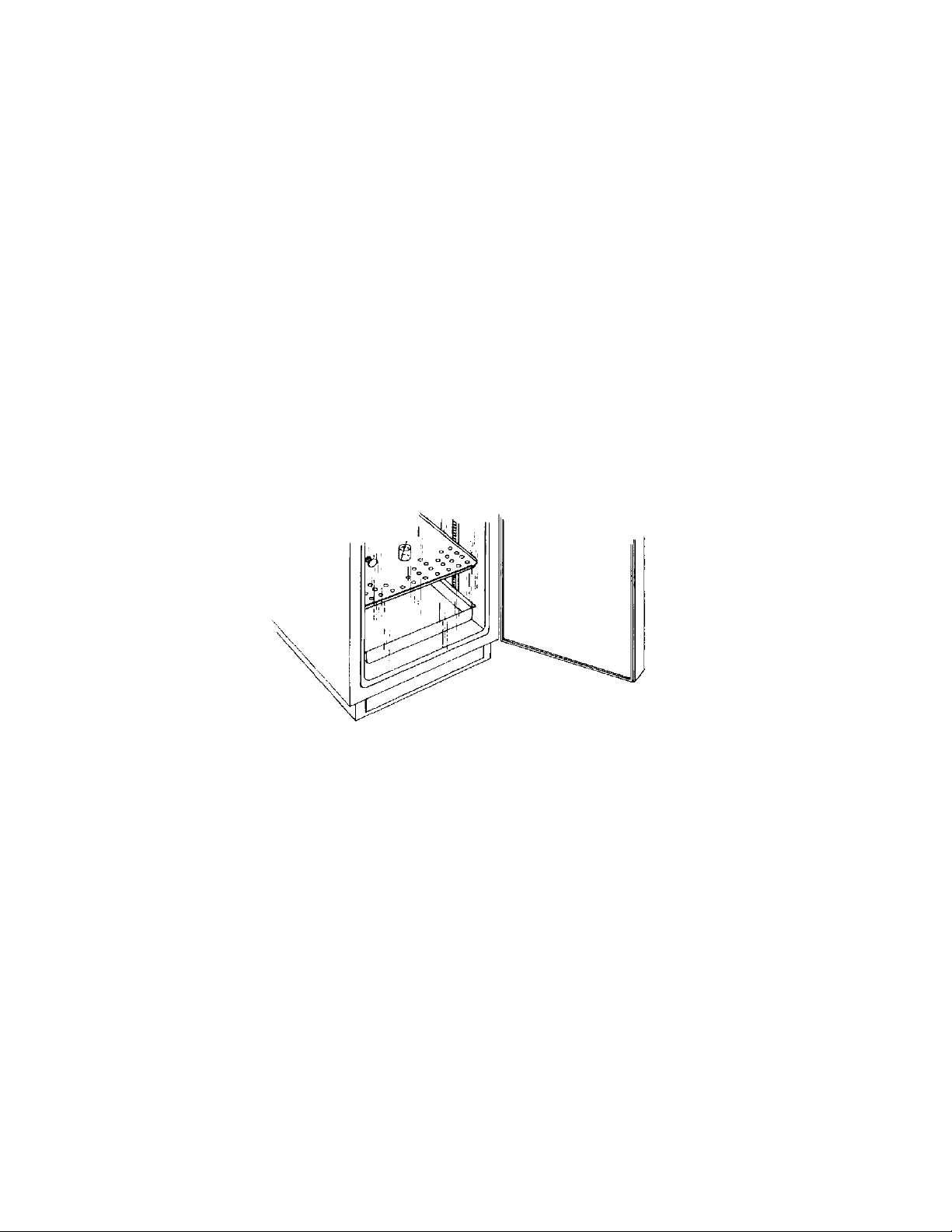
9.0 Calibration
Proper calibration of the incubator involves following parameters. On all models of the Invitrocell incubator the chamber
temperature, door temperature, and CO
regular schedule. The first two, chamber, and door temperature should be completed and stabilized before any CO
calibration is performed. On Invitrocell Below, each calibration procedure is described in detail. For the best results, follow the
procedure carefully, and if the desired result is not achieved, try procedure again from the start.
9.1 Chamber Temperature Calibration
The DH’s TEMPERATURE CALIBRATION MUST BE PERFORMED WITHIN 1°C OF THE PLANNED OPERATING TEMPERATURE.
Normally, 37.0°C is the most common set point. To initiate the procedure, turn on the incubator via the power switch on
the back panel. The default set point is 37.0°C; enter “Environmental Set Points” and adjust if desired Let the unit stabilize
for 8 to 12 hours. Use an independent calibrated instrument to check and calibrate the temperature.
Below is a description of calibration with a glass thermometer as one example for temperature calibration.
At the beginning of this procedure, set a calibrated glass thermometer in a glass beaker filled with water resting on a shelf
in the middle of the chamber. Do not place the glass beaker on the bottom of the chamber because it will result in a slightly
higher temperature reading due to the heater located on the chamber bottom. Placing the thermometer in glass beaker on
the middle shelf will give the most accurate results for calibration. The chamber should be humidified to avoid false low
readings due to evaporation of water from the flask. An accurate digital thermometer with a type K thermal couple could
also be used. No matter what instrument is used the measurement for this calibration should be taken in the middle of the
incubator chamber and in a stabilized condition.
sensor require calibration at installation and the calibration should be checked on a
2
sensor
2
When the unit has stabilized at the operating temperature, perform the following calibration procedure.
• Allow Incubator to stabilize at its given temperature set point in run mode.
• Enter “Service Settings” by means of your provided password.
• Press the Temperature Calibration button.
• Determine actual temperature within chamber by reading temperature measurement instrument.
• Select the number digits below the “Current Calibrated Sensor Reading” blue text button
• Input the current value displayed on your temperature measurement instrument and exit calibration.
Note: THE DISPLAY DOES NOT UPDATE IMMEDIATELY; IT TAKES 2-3 SECONDS
The chamber temperature calibration is complete. Let unit stabilize for 8 to 12 hours. If the chamber temperature (actual
thermometer) still does not match the display, perform the above procedure again. In some cases it might be necessary to
calibrate several times to achieve a stable condition due to ambient conditions of temperature and humidity within the
laboratory.
OM0253 Page 36 of 53
Rev 6 November/2018
Page 37
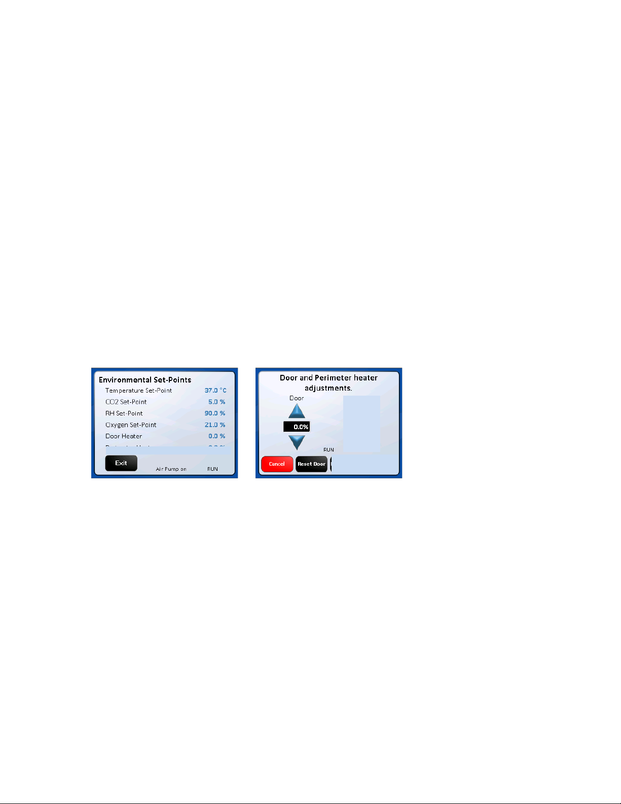
9.2 Door Duty Cycle Adjustments for Temperature Calibration
The Door heater is run on “Base Duty Cycle” calculations that are automatically increased or decreased to run in accordance
with the chamber temperature at a chosen set point. These duty cycles work in the controlled lab environment but due to
the many variables involved in temperature control there is also a manual adjustment. The heater duty cycles can be
adjusted to control condensation or to improve the temperature uniformity in the chamber.
The inner glass door temperature calibration is best accomplished by running the Incubator for
a minimum of 24 hours with the water pan in place and perform the following calibration sequence, if required. Open the
outer Incubator door and look for general condensation. Some condensation on the glass door can be desirable as an
indication of adequate humidity in the chamber. Typically, one to two inches of condensation in the corners of the glass
door and/or gasket indicates a properly calibrated door heater. If calibration is required, simply perform the procedure as
stated below. As stated earlier, the door heater operates on a base duty cycle calculated for the chamber temperature set
point being used. In the door heater (adjustment) screen “0.0” = the calculated base duty cycle. Adjusting the value up or
down will increase or decrease the percent of power to each heater in 0.1% increments. Small adjustments are
recommended to a maximum of 5.0% at a time.
The following steps should be taken for setting these duty cycle percentages:
• Allow Incubator to stabilize at its given temperature and humidity level in run mode.
• Enter the “Environmental Set Points” screen either from the MAIN SCREEN or the SYSTEM SETTINGS screen.
• Select the numerical digits following the “Door” text. Go to the adjustment screen.
• Press UP or DOWN keys to increase or decrease the numerical value to the desired level. The limits the settings can
be changed to are +50 and -20.
• Press “Done” to set current value and exit calibration.
• The reset button for the door heater resets the number displayed to 0.0 removing any adjustment previously
made.
OM0253 Page 37 of 53
Rev 6 November/2018
Page 38

9.3 Setting Air Injections
If there is still some undesired condensation in the chamber when the door heater is set for the desired result, the air
injections can be adjusted. There is a control for length of the air injection labeled, Air Inject Time, and the frequency that
air is injected called, Air Inject Cycle. These controls are described in more detail in the "General Options" section of the
Service Settings menu. The default is 5-second injections every 1 minute. Start by increasing the length of the injection by
a few seconds at a time then increase the frequency if needed. If the humidity in the chamber is less than desired, reduce
the Air Inject Time.
Air and O
When the O
interfere with achieving the lower O
Levels
2
set point is set below 10% the “air inj time” is automatically reduced to 0(zero) to stop air injects which will
2
set points.
2
9.4 CO
The Water Jacket infrared CO
Calibration
2
sensor may be calibrated using one of four techniques: Open Door CO2, Closed Door CO2,
2
Off-Set, and CO
calibrations menu in “Service Settings” and following the on screen instructions. To perform Off-Set, Open Door, and
CO
2
Closed Door calibrations attach an independent CO
injection calibrations. CO2 calibrations can be performed in approximately ten minutes, by accessing the
2
measurement device to the Sample Port in the front of the unit before
2
the calibration begins.
9.4.1 CO
Off Set Calibration
2
CO2 Off Set Calibration can be performed anytime an independent measurement doesn't correlate to the front panel
display. However, this calibration SHOULD NOT BE PERFORMED MORE THAN ONCE PER WEEK. Sensor calibration
should be performed if an independent measurement, if it doesn't match the display within +0.3 percent within one
week after a sensor calibration. Before doing the following calibration, check and change, if necessary, the Incubator
in-line filter found within the Sensor bay.
When unit has stabilized at the operational temperature and CO
percentage, take an independent measurement
2
and, if necessary, perform the following:
• In “Service Settings” enter the CO
• Press the “CO
Offset Calibration” text button
2
• Use an independent instrument to determine actual CO
Calibrations menu.
2
percentage (compare the display CO2 to the
2
independent measurement). If these two readings have a difference equal to or less than 0.5 percent,
proceed to enter the CO
below) If the difference is greater than 0.5 percent, it is recommended to perform a CO
Fyrite value. This calibration only allows a maximum of 0.5% offset. (See * Note
2
Open Door
2
Calibration.
• Enter the value measured by the independent device
• Exit and Save to retain this value.
*Note: When the display value is more that 0.3% different from the measured value, offset display
1/2 the difference measured. Allow the Incubator to stabilize back to set point, then measure
the CO
in the chamber again. Offset the display again if necessary.
2
9.4.2 CO
Sensor Calibration (Zero/Span/CAL. INJ.)
2
There are 2 sensor (zero/span) calibration routines available to the lab professional. The first option is the “open
door” routine involving opening the outer and inner door to zero the sensor. This routine also automatically
calibrates to the CO
injection rate during the injection for the span portion of the sensor calibration. It is
2
recommended that this routine be used during the initial setup of the Incubator, if the set point of the system is
changed or if other changes are made on the Incubator affecting the CO
system.
2
The second option is a “closed door” routine. This routine allows calibration of the sensor without opening the door
avoiding undue exposure to the cultures that may be in process. This routine injects “fresh air” into the detector
head of the sensor to calibrate zero. The chamber air is then allowed back into the detector head to calibrate the gas
span that is detected.
OM0253 Page 38 of 53
Rev 6 November/2018
Page 39

9.4.3 Open Door CO
• Attach independent CO
• Enter CO
• Select the “CO
Sensor Calibration Routine
2
monitoring device to the sample port on the front of the unit
2
calibrations by means of Service Settings
2
Open Door Zero Span” text
2
• Follow on screen instructions
The CO
unnecessary to run the separate “Injection Calibration”. The injection is dependent on the proper gas pressure and
factory set flow rate. Any changes in either will result in a change to the value reached during this injection.
9.4.4 Closed Door CO
inject rate is automatically calculated from the CO2 injection made during the span calibration making it
2
Sensor Calibration Routine
2
• Attach independent CO
• Enter CO
• Select the “CO
calibrations by means of Service Settings
2
Closed Door Zero Span” text
2
monitoring device to the sample port on the front of the unit
2
• Follow on screen instructions
Enter measurement on independent device when prompted
Allow unit to run and stabilize for a minimum of 2 hours then, check calibration with an independent instrument.
Compare the display CO
percent to your independent measurement. If these two readings have a difference
2
greater than 0.3%, repeat above procedure. If these two readings have a difference of less than 0.3%, perform the
Offset calibration procedure in Section 9.4.1.
CO
2
9.4.5 CO
Injection Calibration
2
The CO
time required to recover the CO
injection calibration can be performed separately from zero/span calibration to optimize the gas injection
2
level to set point after a door opening. The recovery time should be as minimal as
2
possible with virtually no overshoot. Verify the CO
sensor calibration prior to performing an injection calibration.
2
The injection calibration is not required after an “Open Door” sensor calibration since it is performed automatically
during this routine. The injection calibration should be performed after a “Closed Door” sensor calibration when
possible, if CO
The following steps should be taken for the CO
• Enter CO
• Select the “CO
supply pressure of the Incubator is changed, or is the CO2 flow control valve is disturbed.
2
injection calibration:
2
Calibrations by means of the Service Settings menu
2
Injection Time” text
2
• Follow the on screen instructions
Calibration – System available on Model NU-8631
9.5 O
2
When unit chamber has stabilized at the operational temperature, CO
least 10 minutes ensuring the sensor is up to temperature - take an O
through the chamber sample port used for taking CO
readings. It is located behind the cover under the incubator outer
2
door and, if necessary, perform the following:
NOTE: If a Fyrite instrument is used,
BE SURE TO READ THE O
FOR PROPER O
MEASUREMENTS AND SAFETY CONSIDERATIONS.
2
FYRITE OPERATING AND SAFETY INSTRUCTIONS
2
Display Offset Calibration:
Press the Calibrate button on the Service settings screen produces the Calibrate the O
sensor reading value to access the key pad to input the independently measured value then press the ENT button on the
key pad. When you return the Calibrate O
offset screen press the save button to return to the System settings screen.
2
Press the exit button in this screen to go back to the main screen.
%, and O2 system has been powered for at
2
measurement with an independent instrument
2
offset screen. Press the Calibrated
2
OM0253 Page 39 of 53
Rev 6 November/2018
Page 40

10.0 Maintaining Your Water Jacket
Water Jacket Chamber
The chamber maintenance is up to the discretion of the owner and the extent of cleanliness and sterility desired.
The shelves and bracket supports are all removable and autoclavable.
The interior should be wiped down with an appropriate disinfectant such as 70% ISOPROPYL ALCOHOL or equivalent.
Note: DO NOT USE ANY CHLORINATED OR HALOGEN MATERIALS IN THE CHAMBER.
SUCH MATERIAL IS HARMFUL TO THE POLISHED STAINLESS STEEL.
NOTE: NuAire does not offer any product warranty with respect to cleaning material compatibility. USE AT YOUR
OWN RISK! The information provided above is from raw material suppliers and known general source documents
for use to develop application cleaning SOP’s.
The humidity pan should also be sterilized and the water changed regularly to assure sterility.
A small amount of copper sulfate may be added to the humidity pan to inhibit bacterial growth.
/ N2 Supply Filter
CO
2
P/N X-980385 (50 mm Disk, Uni-directional In-Line, Dry)*
The CO
Note: Direction of flow (IN is labeled on one side of filter) when replacing filter.
Sensor Bay Capsule Filter
P/N RF566 (Capsule, Uni-Directional In-Line, Wet)
This filter should be replaced EVERY TWO YEARS to assure optimum performance.
A visual check should be performed when maintenance reminder appears in the main screen to assure filter integrity.
Remove sensor bay cover to perform visual check.
Air Supply Filter
P/N X-980385 (50 mm Disk, Uni-directional In-Line, Dry)*
The Air Supply Filter should be replaced every fifth empty CO
Note: direction of flow (IN is labeled on one side of filter) when replacing filter.
CO
P/N X-980366 (50mm Disk, Uni-Directional In-Line, Wet)*
The filter should be changed when discolored (yellow brown).
The filter is plumbed in the chamber sample hose and can be inspected when the cover is removed to check the air pump filter.
This filter has a green dot to distinguish it from the "dry" filter.
/ N2 Supply Filter should be replaced every fifth empty CO2 tank or when the filter is visibly discolored (yellow-brown).
2
tank or when the filter is visibly discolored (yellow-brown).
2
Sensor Filter
2
* Note: The word "In" on the outer rink of the body indicates the inlet side of the filter
and should be installed toward the gas supply.
OM0253 Page 40 of 53
Rev 6 November/2018
Page 41
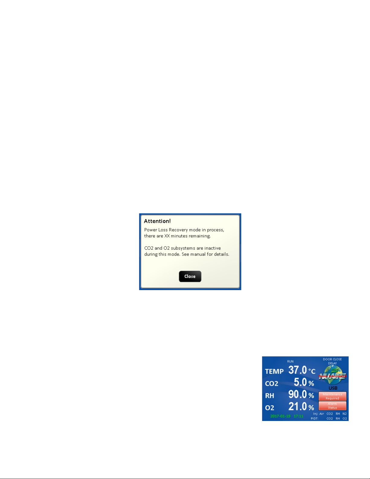
10.1 Chemical Decontamination of the Incubator Chamber
To chemically decontaminate NuAire Incubator inner chambers, users may use the traditional formaldehyde or Chlorine
Dioxide in gas form, or Vapor Phased Hydrogen Peroxide. All three of the chemicals are compatible to all parts within
NuAire Incubator chambers. The incubator should be turned off during these procedures
Note: As stated previously, the chamber and components can also be wiped down with a
70% solution of Isopropyl Alcohol for cleaning and decontamination.
10.2 Power Loss Recovery Mode
When an incubator experiences a sudden loss of power there is an increased chance of condensation building up in the
circulation system tubing. This mode helps to dissipate that buildup before it causes the sensors to fail
- Conditions for entering mode: - Incubator must be without power for 45 minutes or longer. This includes first time
setup. Mode is automatically triggered after power is restored (after 45+ min outage). If less than 45 minutes have
passed incubator will enter normal Run mode.
- When in Power Loss Recovery Mode:
o Blocking solenoid will be turned “ON” which will bypass the CO2 and O2 sensors in the circulation system.
o Both systems will be put in standby mode meaning they will not control or alarm while in this mode.
o “Power Loss Recovery” shows in place of “RUN” in the main screen. Heaters and Air Pump run as normal.
- Once entered, this mode will run for 1 hour. A count down timer screen (seen below) can be found when pressing
the CO2 or O2 Diagnostics button in the Service Settings screen. It is also recorded in the event log.
-
10.3 Shutting down the Incubator
Prior to shutting down the Incubator open the inner and outer doors and remove the water pan. Leave doors open for at
least 5 minutes prior to shutting it off. This will purge the chamber, circulating system and the sensors of humidity that
could condense and cause faulty readings when the Incubator is turned back on. Be sure to empty the water pan prior to
putting it back into the chamber if the Incubator is going to be shut off for any length of time.
10.4 Automatic Filter Change Notification
The Capsule filter located in the Sensor bay (see BCD-18477 for location) should be
checked average every 2 years to see if it should be changed. The Filter material is
normally a white material. Discoloration of the filter material is an indicator that it
should be changed. Retro Fit Kit RF566 should be ordered for the replacement
filter. A timed notice triggers a Maintenance Notification button in the Main Screen
when this timer counts down to zero. Pressing the Maintenance Required button
produces a screen indicating that the timer for filter life has expired.
OM0253 Page 41 of 53
Rev 6 November/2018
Page 42

Responding to the notification:
From the main screen press the NuAire Logo / Service settings / General Option /
Settings / Filter Maintenance to access the Filter Maintenance Adjustments screen.
In this screen you can:
• Extend the alarm by 1 month by pushing the Extend. Press the Exit button
to retain the extension and go the General Settings screen. Pressing Save
will not retain the time extension.
• Reset the notification timer to the default of 24 months by pressing save.
This is recommended.
• Change the timer by sliding the green button right(to decrease)
or left (to increase) the amount of time until the next notification.
The number of months showing will change as the button is moved. Setting the timer to 0 months deactivates
the notification.
• Press the Save button to save the timer setting and go the General Setting screen.
• Setting the timer to 0 months deactivates the notification.
After extending or resetting the timer you can return to the main screen by following the screen prompts to save your
choice and exit the menu.
OM0253 Page 42 of 53
Rev 6 November/2018
Page 43
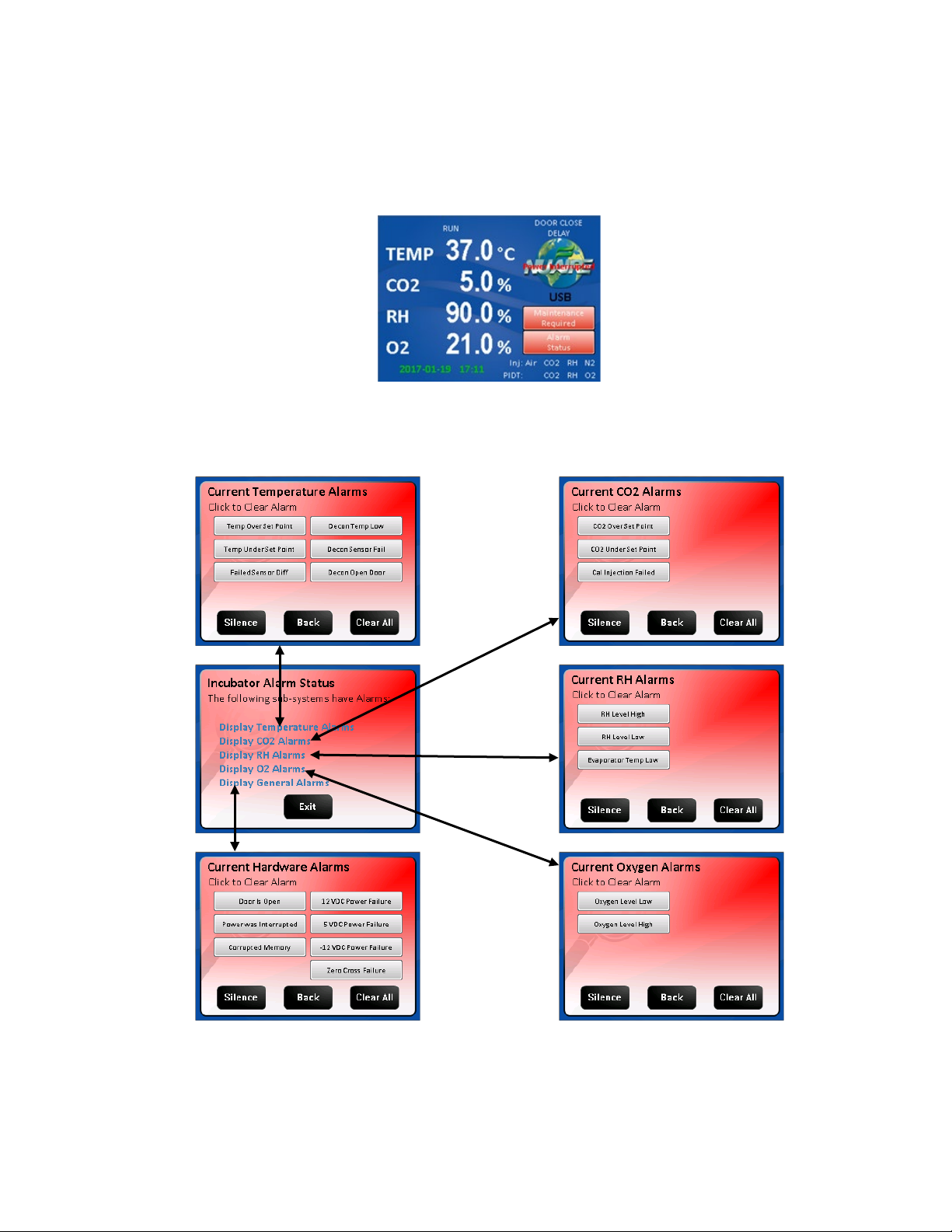
11.0 Error Indicators & Troubleshooting
Step 1 NOTE ALL ERROR INDICATORS
When the Incubator is running, the Alarm Status button indicates an error.
Pressing the Alarm Status button, entering the correlating Alarms Menu and pressing the Silence button in the
Alarms Menu will silence the audible alarm until Diagnostics is entered or another alarm becomes active.
Step 2 CLEAR ERROR INDICATORS.
Error indicators can be cleared by entering the Alarms Menu and pressing the Clear All button; if the error is still
present the indicator will return when the alarm time reaches 0.
Step 3 MONITOR REOCCURRENCE OF ERROR INDICATORS.
If reoccurrence of the error indicator is immediate or daily, use guide below to correct the situation.
OM0253 Page 43 of 53
Rev 6 November/2018
Page 44
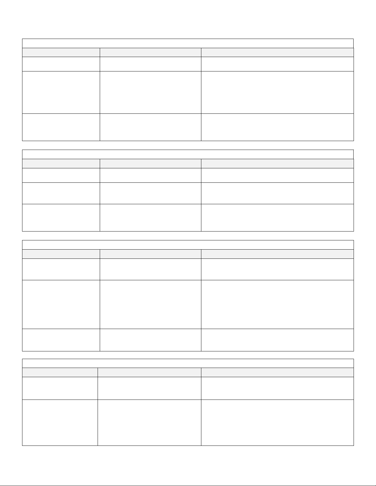
-Temperature over set point
− Check temperature sensor calibration.
Faulty TRIAC, replace control board.
− Check temperature sensor calibration.
set-point in a low ambient temperature.
-Sensor temperature (differential)
sensors exceeds 4°C.
− Check temperature sensor calibration.
− Confirm it is plugged in at board connector P6.
− Replace CO2 shroud temperature sensor.
Check control board output to relay, replace board if faulty.
Check sensor bay heater for function, replace if faulty.
Check control board output to relay, replace board if faulty.
Check for uncontrolled sources of heat influencing the bay.
− Perform CO2 sensor calibration.
Check sensor and disk filter for condensation.
− Check CO2 gas supply - inline gas filters, CO2 gas tank pressure,
Check for leaks in air pump and hosing.
- Cal inject calibration failed.
− Check gas supply then run calibration again.
O2 System
Displayed Error Code
Code Description
Checks and Corrections
− Perform O2 sensor calibration.
Check sensor and disk filter for condensation.
− Check O2 gas supply - inline gas filters, CO2 gas tank
Error Indicator Troubleshooting Guide
Temperature System
Displayed Error Code Code Description Checks and Corrections
Temp Over Set Point
Temp Under Set Point
Failed Sensor Differential
Displayed Error Code Code Description Checks and Corrections
Temp Sensor Failure -Defective shroud temperature sensor
Sensor Bay Temp Low
Sensor Bay Temp High Sensor bay temp is above 65 deg C
Displayed Error Code Code Description Checks and Corrections
Normal mode
-Temperature time out error
during normal running and in
error normal running.
-Occurs when difference between
CO2 Sensor Shroud Heater
Sensor bay is below temp set point +2⁰ -
diagnostics screen
See CO
2
CO2 System
−
− Replace fuse.
− Faulty TRIAC, replace control board.
− Faulty chamber heater contact NuAire Technical Service.
− Door heater needs to be increased with a high temperature
− Check connection on control board.
− One or both temp sensors faulty, replace.
−
− Check that all connections are secure.
−
Check that all connections are secure
Check sensor bay heater for function, replace if faulty.
CO2 Over Set Point - CO2 over set point
- CO
time out error. The measured
2
CO2 level has not reached with in the
CO2 Under Set Point
allowed percentage in the allowed
time. CO2 stops injecting and air is
injected for 15 minutes in case the
sensor is not detecting the CO2.
Cal Inject Failed
Not enough increase in the CO2
reading after gas was injected.
O2 Under Set Point - O2 under set point
O2 Over Set Point - O2 time out error
OM0253 Page 44 of 53
Rev 6 November/2018
− Check injection solenoid for leaking valve.
−
CO2 sensor function.
− Run Cal Inj. Calibration (see Section 9.3.3).
− Check/replace CO2 gas supply tanks.
− Check for leaks in chamber - inner door gasket, recirculation
tubes.
−
− Call NuAire Technical Services if error persists.
− Check injection solenoid for leaking valve.
−
pressure, O2 sensor function.
− Check/replace O2 gas supply tanks.
− Check for leaks in chamber, inner door gasket, chamber
blower fan shaft seal.
− Check for leaks in air pump and hosing.
Page 45

General Indicators
- Inner glass door is not closed or switch
− Close and latch inner glass door.
Check door switch, if faulty, replace.
“Power Interuption” Text
instead of the NuAire Logo
Flashing Green:
return the date and time to green text.
Shows when incubator has lost power for more than 45
dissipate. Gas control is then resumed.
Corrupted memory was detected during
boot up of the incubator
− Replace Control Board.
A change in parameters failed to write
to memory
− Replace Control board.
− Check output @ Power Supply. If good, could be Control Board.
DC power supply failed. Replace.
− Check output @ Power Supply. If good, could be Control Board.
DC power supply failed. Replace.
− Check output @ Power Supply. If good, could be Control Board.
DC power supply failed. Replace.
− Check that AC line voltage to the board is at the correct level. If
Replace Control Board.
Memory stick no compatible try another one. May take several
USB port not functioning contact Nuaire technical service
- Glass door, gasket or front wall of
chamber is wet.
− Increase door heater duty cycles.
See section 9 for detailed instructions.
− Decrease door heater duty cycle.
− See section 9 for detailed instructions.
Condensation Persists After
Door Duty Cycles are Adjusted
− Increase air injections, increasing duration first, recommended
initial change to 6 sec (Air Inj) & 1 minute (Air Cyc).
− Check side access port stopper pressure relief hole(s) for
chamber to be less than flow into the chamber.
Displayed Error Code Code Description Checks and Corrections
Door Ajar
not making connection with the control
board.
- Interruption of power
date/time flashing - Interruption of power
Power Loss Recovery Mode
Corrupted Memory
Data Write Failure
Displayed in main screen in place
of RUN or STANDBY.
− Confirm connection on the Control Board.
−
− Press the power interruption text to dismiss the notice.
Indicates that the real time clock did not lose power. See
section 8.7.1.1 to address this. Canceling or saving in the
clock set screen will return to the main screen and stop the
flashing.
Flashing Yellow
Indicates the real time clock lost backup power and needs to
be set again. See section 8.7.1.1 to address this. Save must
be pressed in the clock set screen to stop the flashing and
minutes long enough to get condensation in the circulation
system and cause the CO2 and O2 sensors to malfunction.
This mode blocks circulation through the sensors and does
not control the gas for 1 hour to allow the condensation to
+ 12 VDC Power Failure
- 12 VDC Power Failure
5 VDC Power Failure
Zero Cross Failure
Universal Serial Bus Error
Condensation Excessive
(Humidity pan in place)
Note: Depending on the ambient conditions where the Incubator is operating, the operator may have to readjust the door heater duty cycle.
Low voltage detected on the 12 VDC
power circuit
Low voltage detected on the 12 VDC
power circuit
Low voltage detected on the 5 VDC
power circuit
The Power Triacs control circuit not
working
Stops trying to write to USB memory
stick after several tries
- Back wall bottom and top walls
If the door heater cycle is too low, the glass door and front wall of the chamber will show excessive condensation. If the door heater
duty cycle is too high, the back wall or sides will have excessive condensation.
− Check power supply connection to Control Board
− Check power supply connection to Control board
− Check power supply connection to Control board
not, trouble shoot cause and correct.
− Check for loose line voltage connection to control bd.
− Replace fuse with slow blow fuse of the correct amp rating as
specified on the wiring diagram.
−
tries
−
Condensation on the face of
the incubator outside of the
chamber
OM0253 Page 45 of 53
Rev 6 November/2018
Pressure in chamber high enough to
cause blow by around the inner door
gasket
blockage.
− Check circulation system for blockage causing flow out of the
Page 46
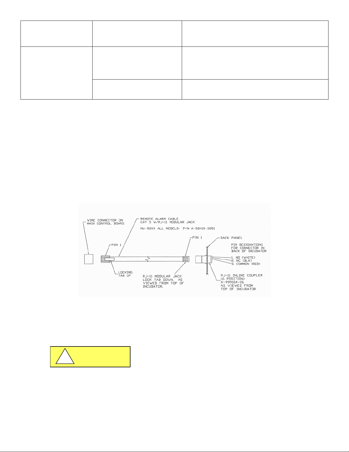
Excess Vibration
− Check for and remove the block of shipping foam from under
room where the incubator is installed.
− Check and Change filters in sensor bay and reset timer.
Responses.
− Fill Water Jacket with single distilled water no purer
Float switch bad. Replace.
CAUTION
!
the air pump.
− Turn the incubator off. If the vibration persists, it is from the
Press button
Message says it is time to change
Maintenance Required
Button in Main Screen
For further assistance, call NuAire Customer Service at 1-800-328-3352 or (763) 553-1270 USA.
Filter
Message says Water Supply Low
− Check Filter and extend timer if filter doesn’t need
− Changing.
− Extend Timer – See section 10.4 for more detail on all
−
− Than 1 Mega Ohm per instructions in manual.
−
12.0 Communication Outputs
12.1 Remote Alarm Contacts
The NuAire Water Jacket Incubator contains a set of contact points to connect to a remote alarm system. The contacts
are located on the rear panel (see page 14). The contacts are housed in a modular (RJ-11) telephone jack and rated for
(30V at 1 Amp). The contacts provided are normally open (NO), normally closed (NC) and common (COM) as shown
below. The alarm contacts do not distinguish between a CO
the contacts upon an alarm condition. Power interruption will also change the state of the contacts.
12.2 4 to 20mA Analog System Performance Output: Refer to PTB0235 rev 3 or higher
12.3 RS-485 2-way Communications: Refer to PTB0234
12.4 On-Board USB Port:
Uploading Service Performance/Event Data: Refer to STB0348
Uploading Incubator Programming: Refer to PTB0347
When connecting external accessories or components to the system,
attach only components that have been tested and certified for
compliance to UL/IEC 60601-1 or UL/IEC 60950
temperature and any other alarm. Each will open or close
2
OM0253 Page 46 of 53
Rev 6 November/2018
Page 47

WARNING
!
13.0 Electrical/Environmental Requirements
13.1 Electrical
Model: NU-8600 and NU-8631
Domestic Units: 115V, 50/60Hz, 1 Phase, 5 Amps
“E” Units: 230V, 50/60Hz, 1 Phase, 3 Amps
Start Up Power 575 Watts
Running Power 250 Watts
13.2 Operational Performance (for indoor use only)
Environment Temperature Range: 60°F-85°F (15°C – 30°C)
Environment Humidity: Maximum relative humidity 80% for temperatures up to
31°C decreasing linearly to 50% relative humidity at 40°C
Environment Altitude: 6562 ft (2000 m) over sea level maximum
13.3 Light Exposure
Standard Fluorescent Lighting @ 150 ft. candles (1614 LUX) maximum intensity.
13.4 Installation Category: 2.0
Installation category (overvoltage category) defines the level of transient overvoltage, which the instrument is designed
to withstand safely. It depends on the nature of the electricity supply and its overvoltage protection means. For
example, in CAT II, which is the category used for instruments in installations supplied from a supply comparable to public
mains such as hospital and research laboratories and most industrial laboratories, the expected transient overvoltage is
2500V for a 230V supply and 1500V for a 120V supply.
13.5 Pollution Degree: 2.0
Pollution degree describes the amount of conductive pollution present in the operating environment. Pollution degree
2.0 assumes that normally only non-conductive pollution such as dust occurs with the exception of occasional
conductivity caused by condensation.
13.6 Chemical Exposure
Chemical exposure should be limited to antibacterial materials used for cleaning and disinfecting. Chlorinated and
Halogen materials are not recommended for use on stainless steel surfaces. Chamber decontamination can be
accomplished by paraformaldehyde, vapor phased Hydrogen Peroxide or Ethylene Oxide without degradation of cabinet
materials.
13.7 EMC Performance (classified for light industrial)
Emissions: EN61326
Immunity: EN61326
Class A equipment is intended for use in an industrial environment.
In the documentation for the user, a statement shall be included drawing
attention to the fact that there may be potential difficulties in ensuring
electromagnetic compatibility in other environments, due to conducted
as well as radiated disturbances.
OM0253 Page 47 of 53
Rev 6 November/2018
Page 48
13.8 Heat Rejection: 14 BTU/Minute.
Component
Material
Incubator Cabinet
Painted Steel
Outer Door
Painted Steel
Chamber
Stainless Steel
Outer Door Gasket
Vinyl Clad Magnet
Inner Door Gasket
Silicon Rubber
Front Service Panel
Painted Steel
Electronics Panel
Painted Steel
Sensor Bay
Aluminum
Exhaust Filter
Aluminum
Hosing
Silicon Rubber
Tubing
Stainless Steel
Air Pump
Various Steel/Copper/Nylon
Motor
Various Steel/Copper/PVC
Printed Wiring Assembly
Lead Free Electronic
Wire
PVC Coated Copper
Solenoid Valves
Various Steel/Copper
Connectors
PVC
Hardware
Stainless Steel and Steel
BIOHAZARD
RECYCLE
LEAD FREE
CAUTION
!
14.0 Disposal and Recycle
Incubators that are no longer in use and are ready for disposal contain reusable materials. ALL components with the
exception of the HEPA filters may be disposed and/or recycled after they are known to be properly disinfected.
Note: Follow all local, state and federal guidelines for disposal of HEPA filter solid waste.
Prior to any disassembly for disposal the incubator must be decontaminated
Note: Material type can be verified with use of a magnet with stainless and aluminum being non-magnetic.
OM0253 Page 48 of 53
Rev 6 November/2018
Page 49
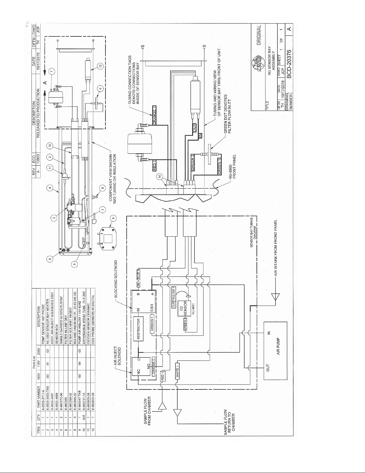
OM0253 Page 49 of 53
Rev 6 November/2018
Page 50
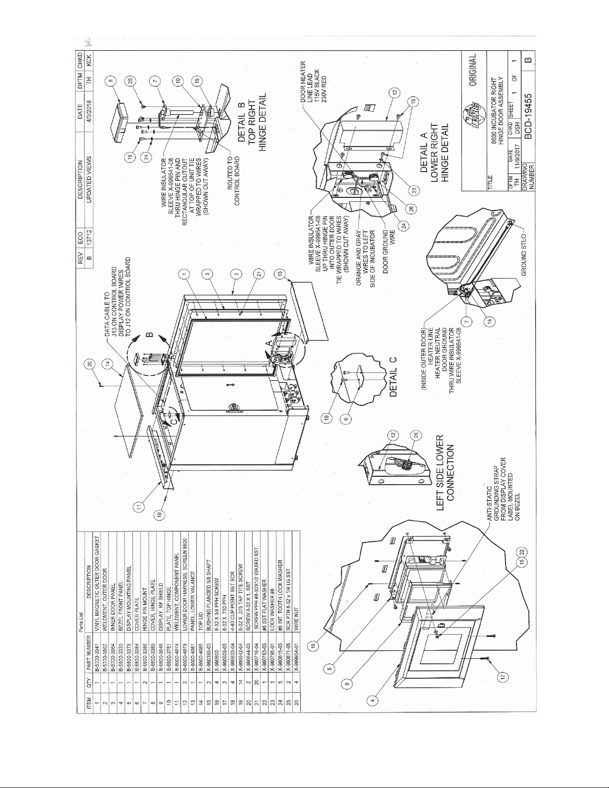
OM0253 Page 50 of 53
Rev 6 November/2018
Page 51
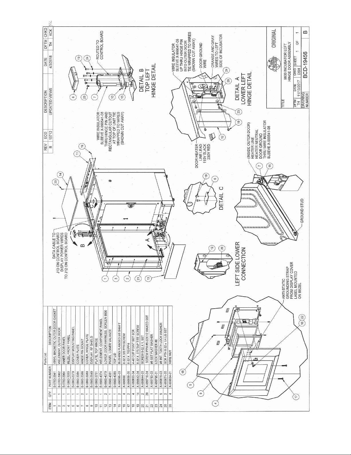
OM0253 Page 51 of 53
Rev 6 November/2018
Page 52
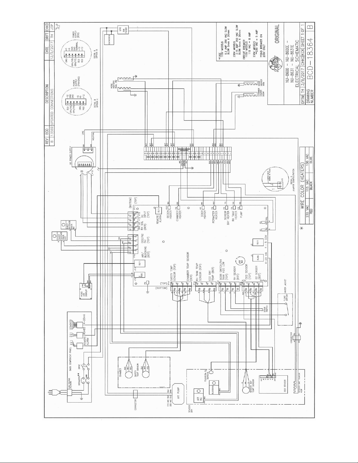
OM0253 Page 52 of 53
Rev 6 November/2018
Page 53
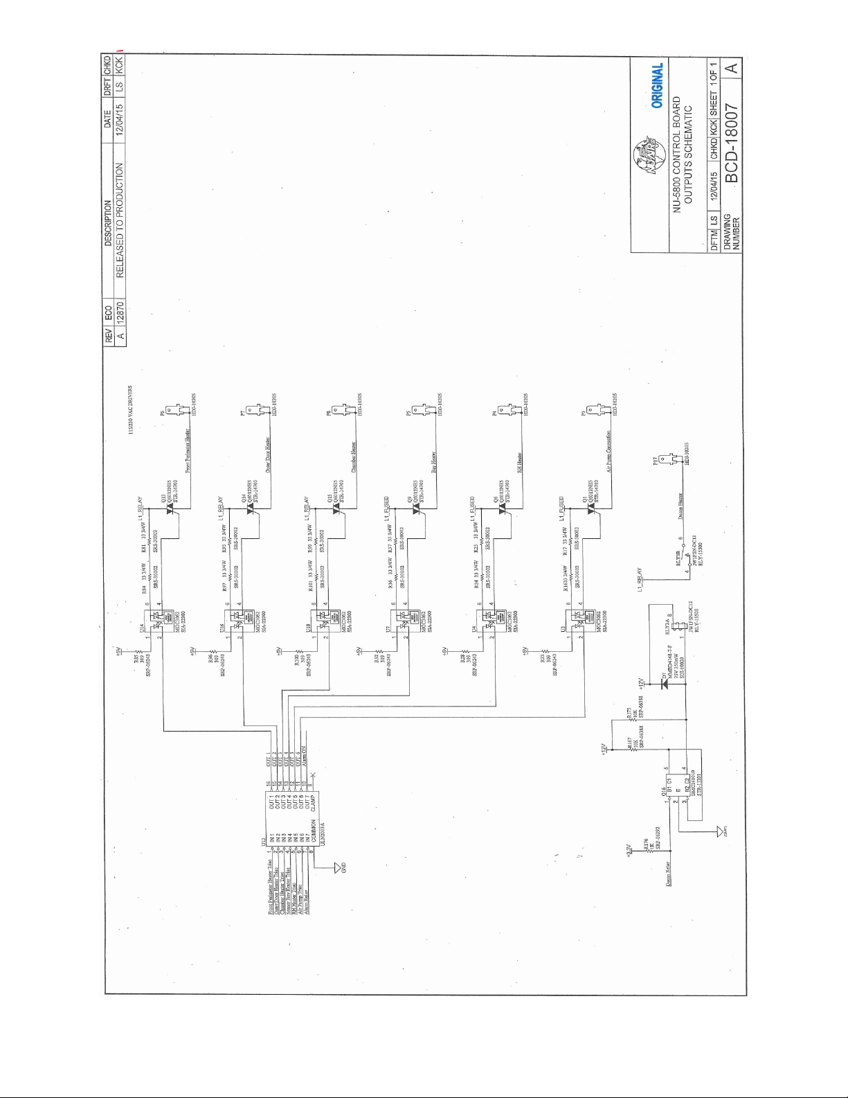
OM0253 Page 53 of 53
Rev 6 November/2018
 Loading...