

Page 1
Page 2

TABLE OF CONTENTS
CHAPTER 1……....
CHAPTER 2…........
CHAPTER 3……….
CHAPTER 4……….
CHAPTER 5……….
CHAPTER 6……….
CHAPTER 7……….
CHAPTER 8……….
CHAPTER 9………
CHAPTER 10……..
CHAPTER 11……..
CHAPTER 12……..
CHAPTER 13……..
CHAPTER 14……..
CHAPTER 15……..
CHAPTER 16……..
CHAPTER 17……..
CHAPTER 18……..
CHAPTER 19……..
APPENDEX A..…...
APPENDEX B…….
SPECIFICATIONS ..........................................................................................1
PRECAUTIONS ..............................................................................................2
MACHINE ORIENTATION ...........................................................................3
GENERAL MAINENANCE ...........................................................................5
Recommended Lubricants and Fluids ......................................................6
ELECTRICAL CONTROLS AND OPERATION ..........................................9
REEL STANDS, REELS AND EXPANDABLE ARBORS .........................16
HYDRAULIC SYSTEMS .............................................................................22
Maintenance ...........................................................................................22
Hydraulic Fluid Troubleshooting ...........................................................22
Changing Hydraulic Fluid and Filter .....................................................22
DRIVE SYSTEM ...........................................................................................26
SHEAR ASSEMBLY .....................................................................................30
BEAD AND STRIATION ROLLER ASSEMBLY.......................................34
ENTRY GUIDE ADJUSTMENT ..................................................................36
CLIP RELIEF ROLLER ASSEMBLY ..........................................................39
ENTRY DRUM ASSEMBLY .......................................................................40
WIDTH CHANGE PROCEDURE ................................................................41
PROFILE CHANGEOVER PROCEDURE ..................................................49
ROLLER SYSTEMS AND PANEL PROFILE DRAWINGS ......................63
RUN OUT TABLES AND REMOTE LIMIT SWITCH ...............................84
QUICK CHANGE POWER PAC ..................................................................87
TROUBLESHOOTING .................................................................................89
PLC CONTROLLER .......................................................................................1
Home ........................................................................................................2
Manual Operation ....................................................................................2
Automatic Operation ................................................................................2
Job Entry ..................................................................................................3
Programming Jobs ...................................................................................3
Clear Jobs .................................................................................................4
Auto Run ..................................................................................................4
Automatic Operation ................................................................................5
On the Fly Calibration .............................................................................5
Calibration................................................................................................5
Setup: .......................................................................................................6
Status/Diagnostics: ...................................................................................7
Security: ...................................................................................................8
Coil Tracking: ..........................................................................................9
Colors .....................................................................................................10
Coil Length Calculator ...........................................................................11
ELECTRICAL SCHEMATICS .......................................................................1
i
Page 3

LIST OF FIGURES
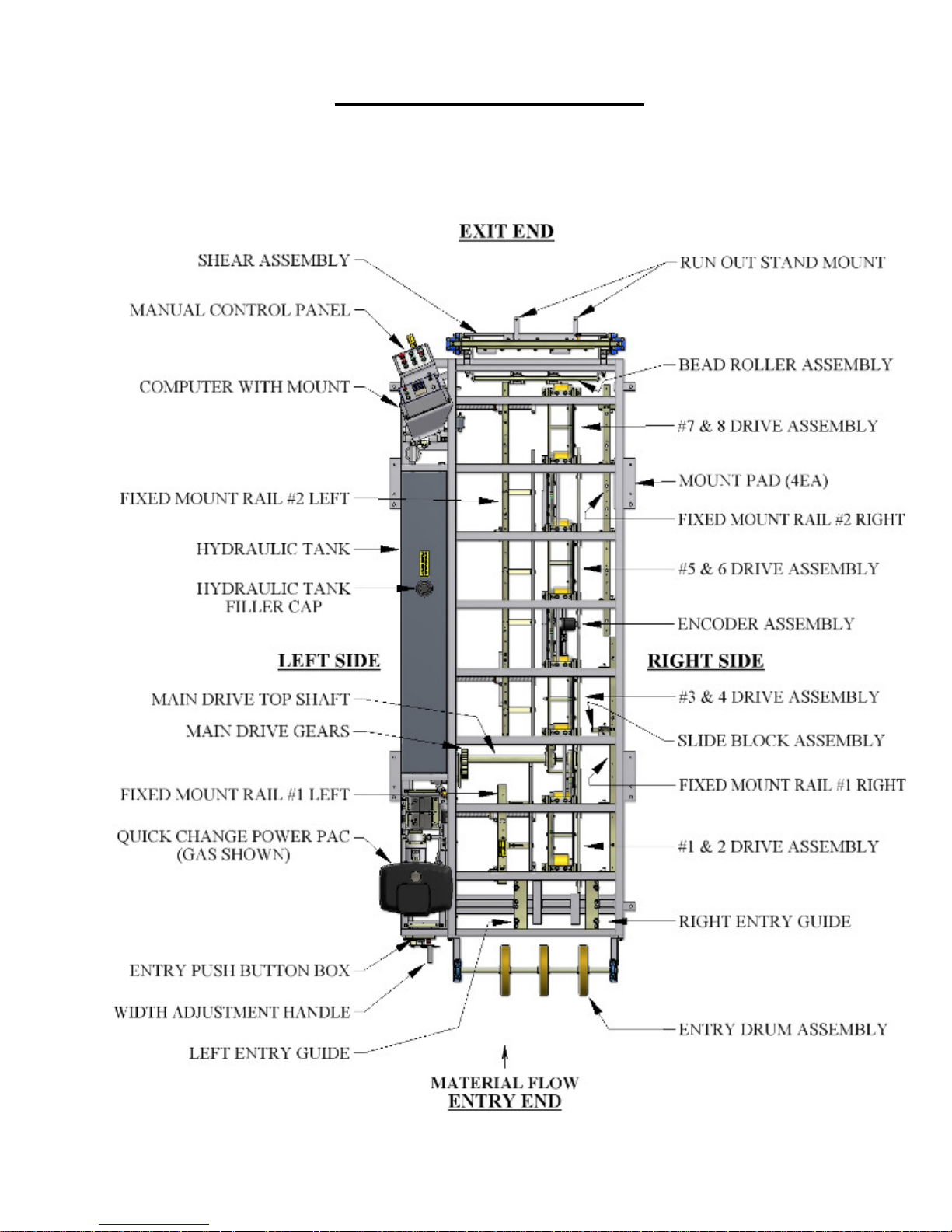
Figure 1: Machine Orientation ............................................................................................................ 3
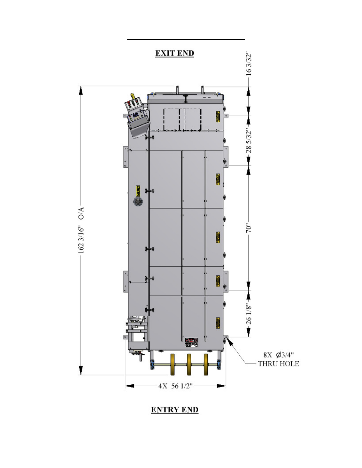
Figure 2: Mounting Foot Detail .......................................................................................................... 4
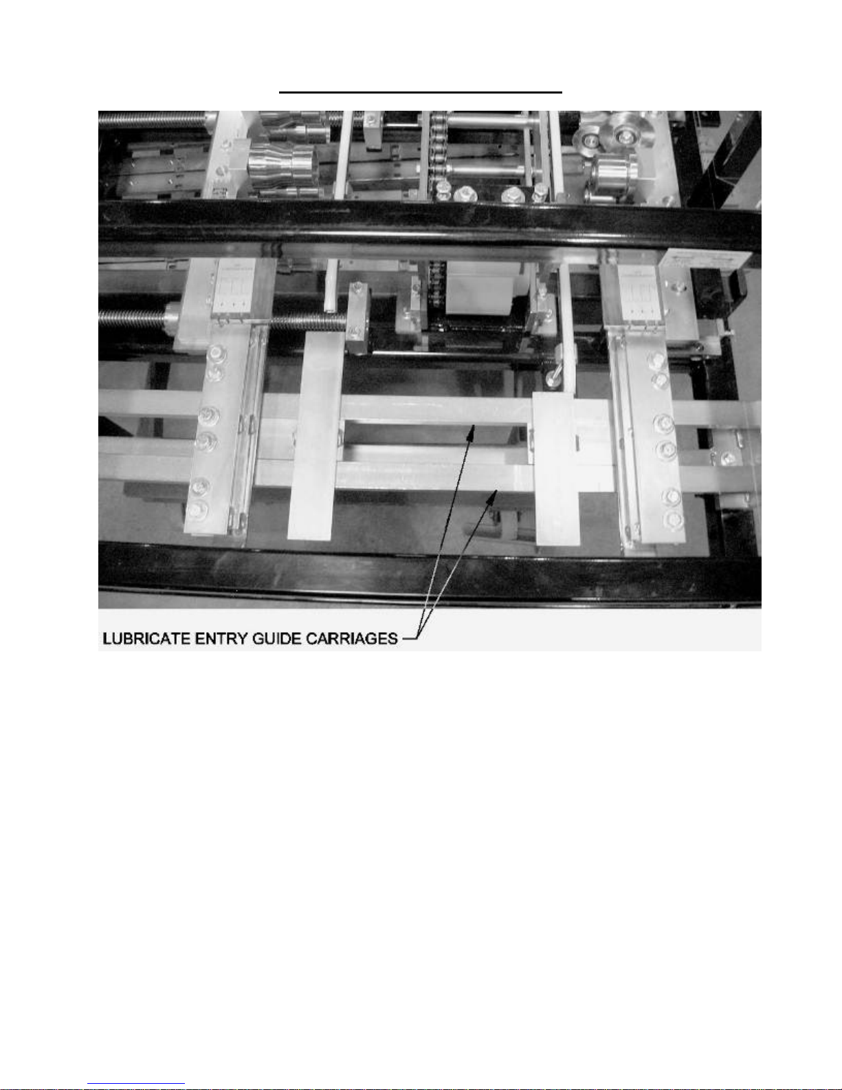
Figure 3: Entry Guide ......................................................................................................................... 7
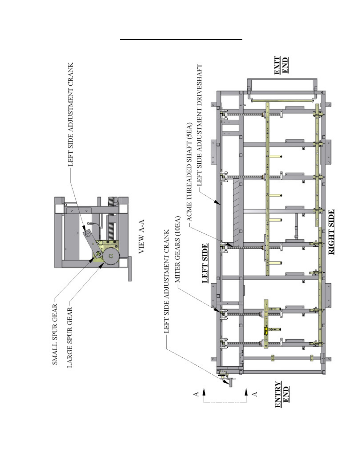
Figure 4: Acme Shafts and Left Side Adjustment .............................................................................. 8
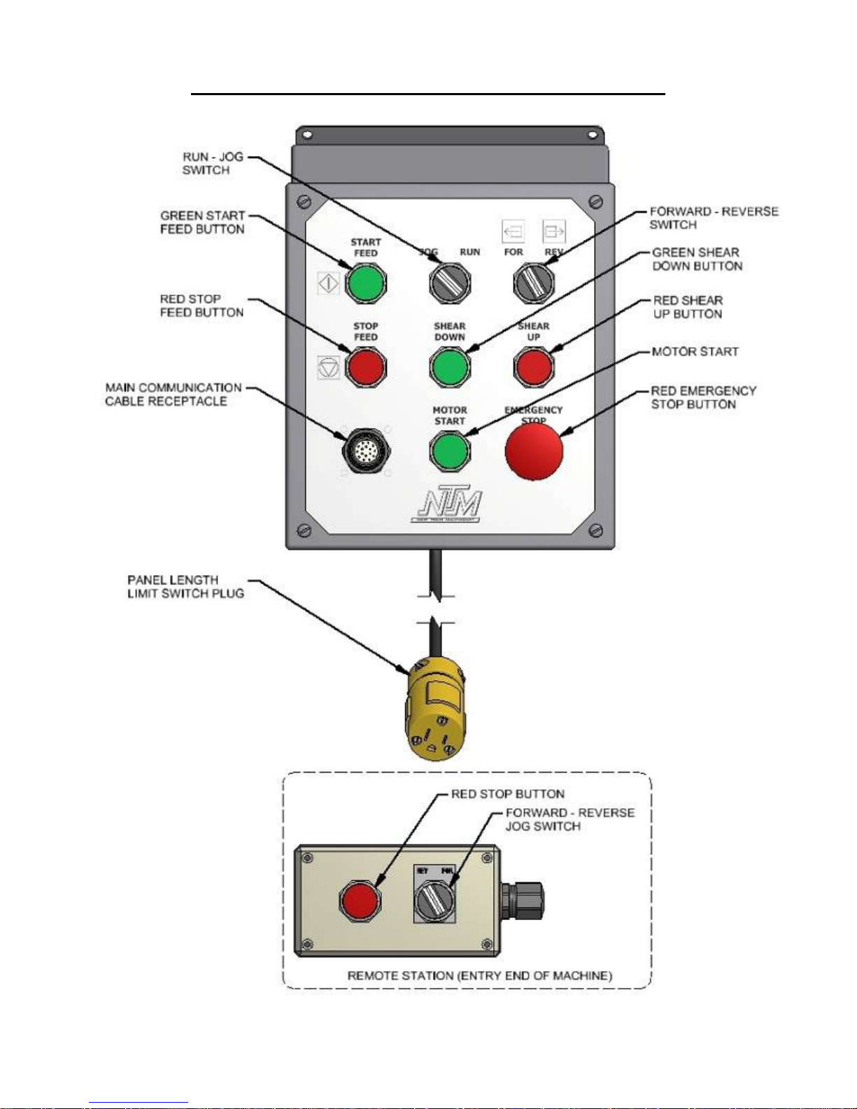
Figure 5: Controls ............................................................................................................................. 12
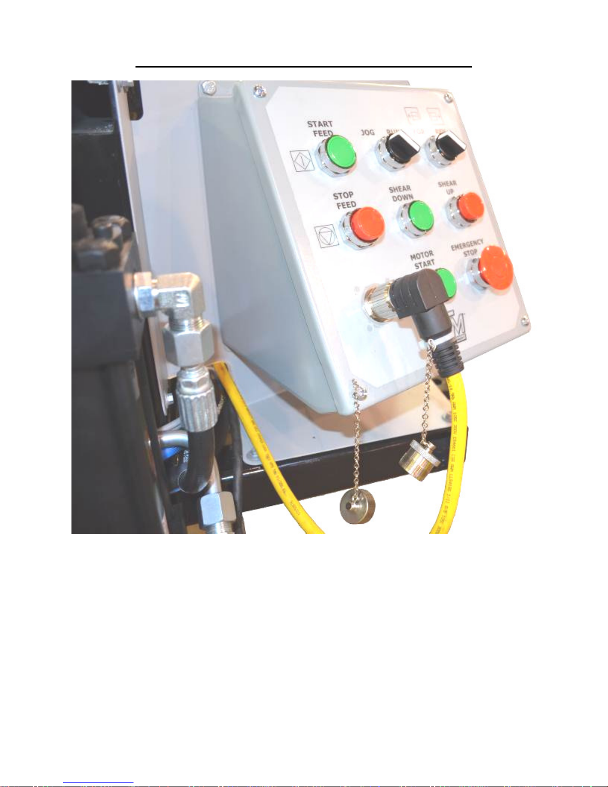
Figure 6: Main Control Cable ........................................................................................................... 13
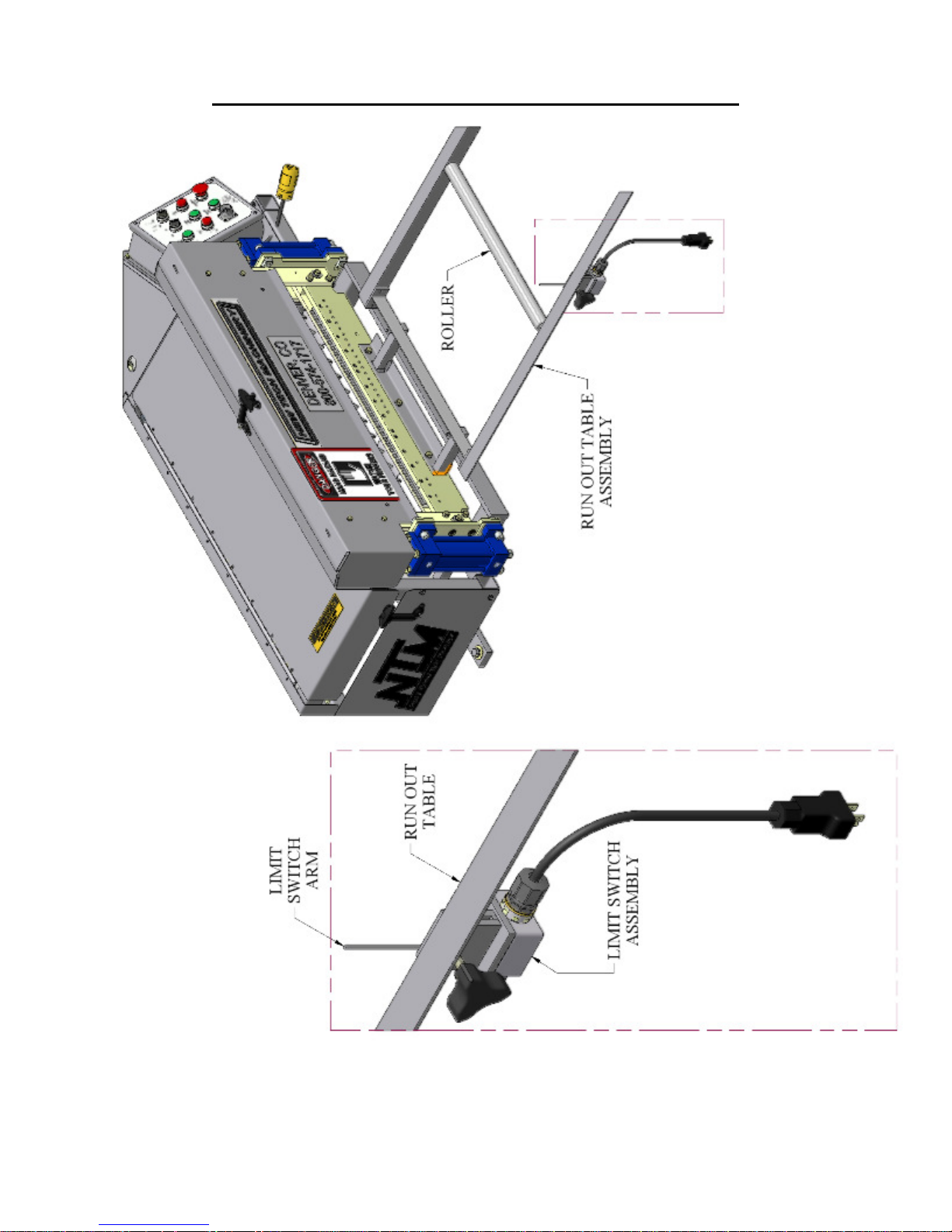
Figure 7: Run Out Table and Remote Limit Switch ......................................................................... 14
Figure 8: Main Control Box Fuse ..................................................................................................... 15
Figure 9: QCPP E 1-6 Fuse Location ............................................................................................... 15
Figure 10: Expandable Arbor Set-Up ............................................................................................... 17
Figure 11: Expandable Reel Assembly ............................................................................................. 19
Figure 12: Material Routing.............................................................................................................. 21
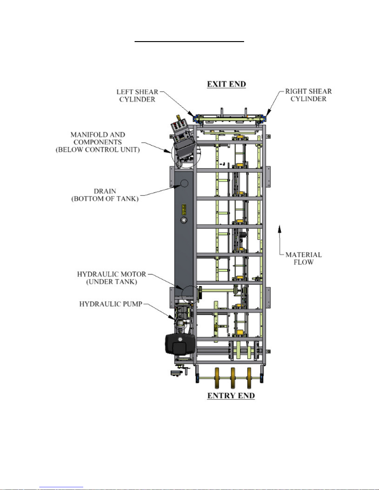
Figure 13: Hydraulic System – Overview ........................................................................................ 23
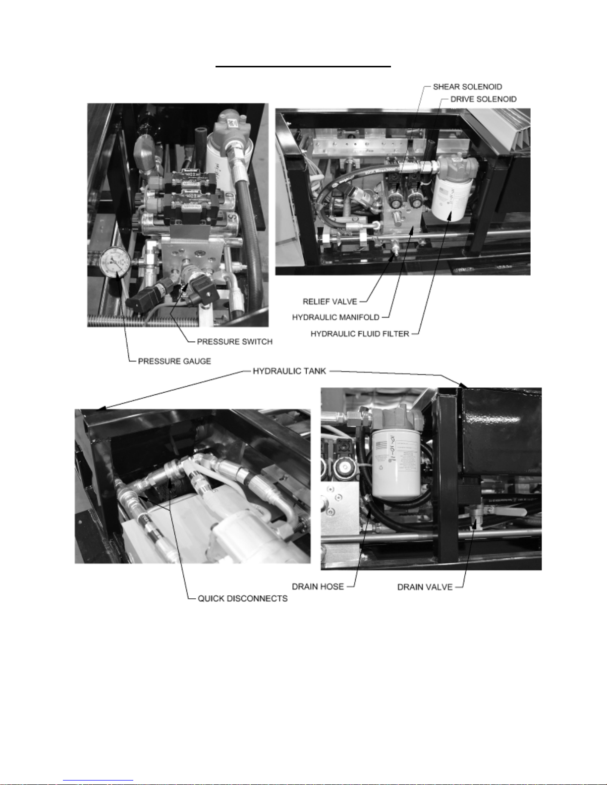
Figure 14: Hydraulic System – Details ............................................................................................. 24
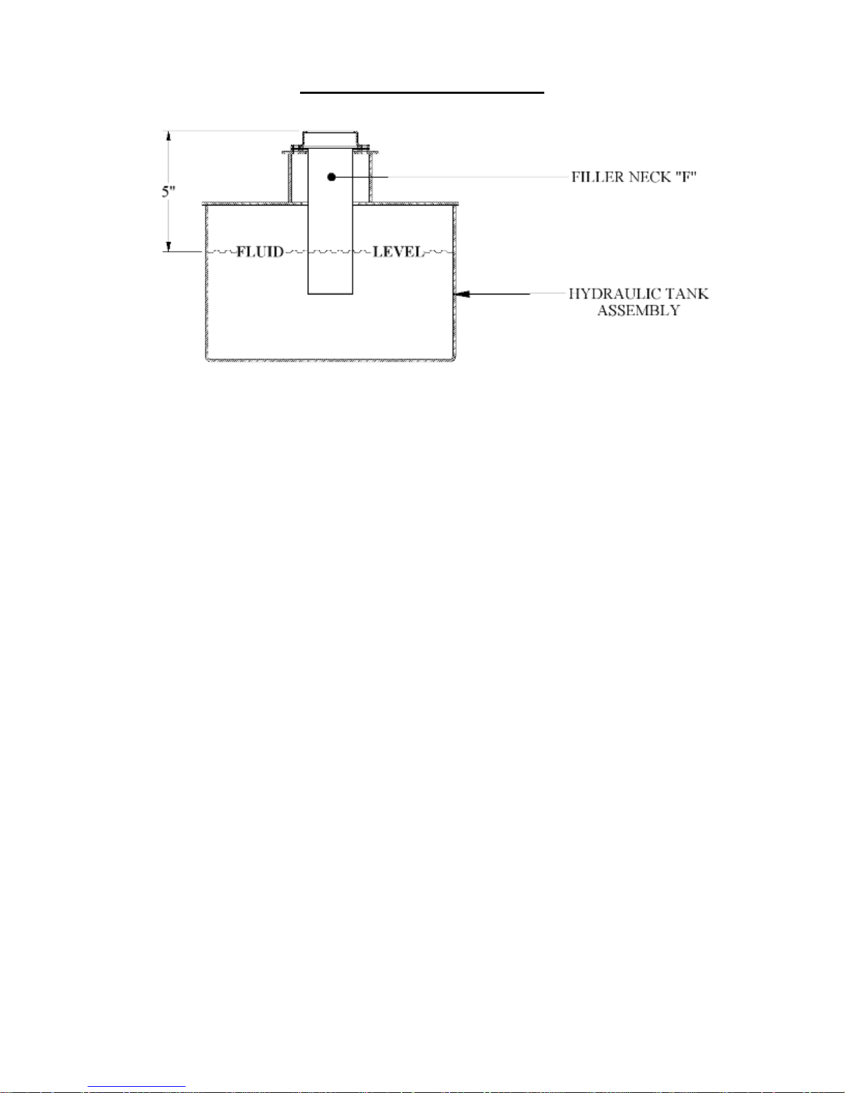
Figure 15: Hydraulic Fluid Level ..................................................................................................... 25
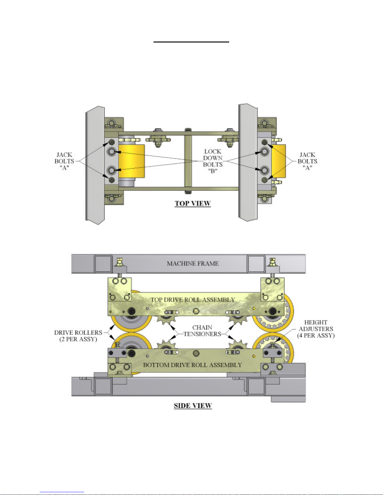
Figure 16: Drive Roll Assembly View ............................................................................................. 27
Figure 17: Gears and Shafts .............................................................................................................. 28
Figure 18: Chains Upper and Lower ................................................................................................. 29
Figure 19: Entry/Exit Views ............................................................................................................. 31
Figure 20: Shear Die Detail Views ................................................................................................... 32
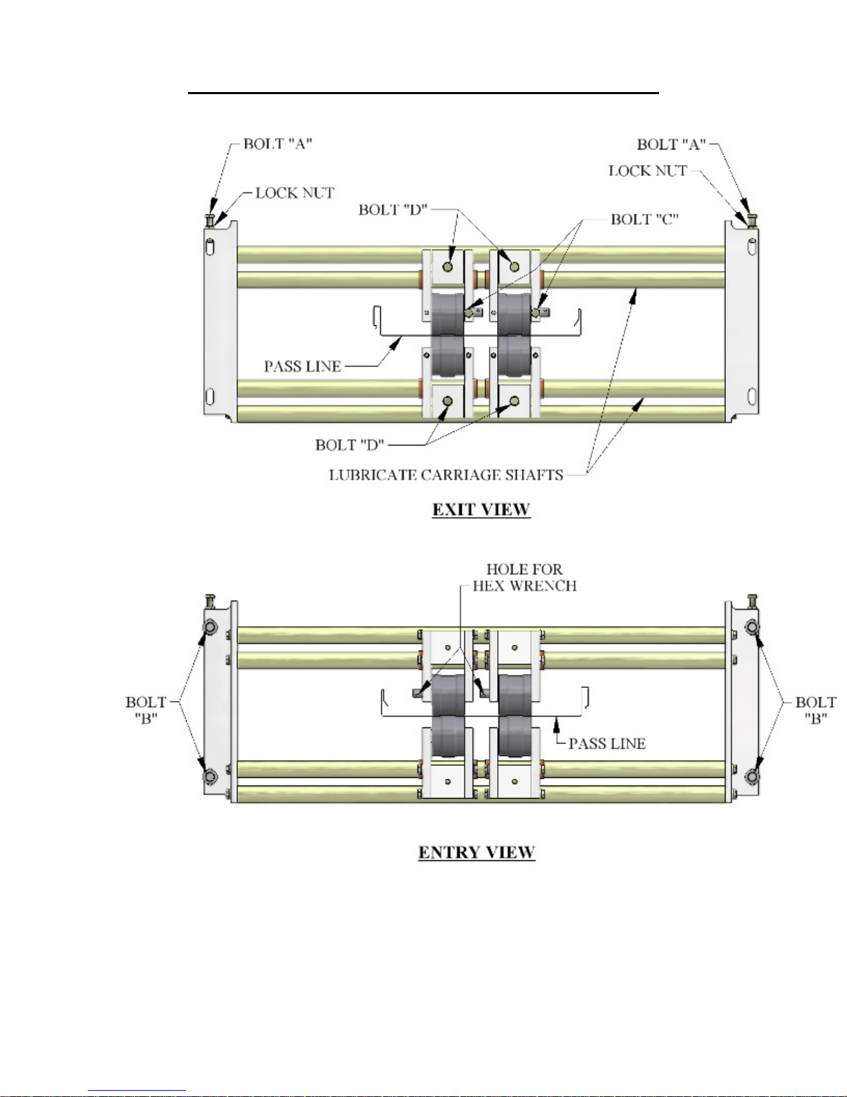
Figure 21: Bead Roller Assembly ..................................................................................................... 35
Figure 22: Right Entry Guide ........................................................................................................... 36
Figure 23: Entry Guide Assembly .................................................................................................... 37
Figure 24: Tooling Rail Adjustment Handle .................................................................................... 38
Figure 25: Marker Plate & Alignment Pin ........................................................................................ 38
Figure 26: Disengaged ...................................................................................................................... 38
Figure 27: Engaged ........................................................................................................................... 38
Figure 28: Clip Relief Roller Assembly ........................................................................................... 39
Figure 29: Entry Drum ...................................................................................................................... 40
Figure 30: Entry Guide Bolts "A" ..................................................................................................... 41
Figure 31: Expandable Arbor Setup ................................................................................................. 42
Figure 32: Loading Material ............................................................................................................. 43
Figure 33: Bead Roller Alignment .................................................................................................... 44
Figure 34: Bead Roller Width Change .............................................................................................. 45
Figure 35: Shear Bolts ...................................................................................................................... 46
Figure 36: Exit Die Adjustment ........................................................................................................ 47
Figure 37: Remove Top Covers ........................................................................................................ 49
Figure 38: Removing Tooling Rails ................................................................................................. 50
Figure 39: Block Chart...................................................................................................................... 50
Figure 40: Inboard/Outboard Positions ............................................................................................. 51
Figure 41: April 2009 and later ......................................................................................................... 52
Figure 42: Machines made before April 2009 .................................................................................. 52
Figure 43: Right Side Fixed Mount Rail........................................................................................... 53
Figure 44: Profile Chart .................................................................................................................... 53
Figure 45: Left Side Fixed Mount Rail ............................................................................................. 54
Figure 46: Shown in the “A” position............................................................................................... 54
Figure 47: Tooling Rail Identification .............................................................................................. 55
ii
Page 4

LIST OF FIGURES
Figure 48: R1 Tooling Rail Spacers.................................................................................................. 55
Figure 49: L1-1 Special Instructions................................................................................................. 56
Figure 50: Entry Guide Alignment Notches and Pins ...................................................................... 57
Figure 51: Tooling Rail Adjustment Handle .................................................................................... 57
Figure 52: Marker Plate Notch and Pin ............................................................................................ 58
Figure 53: Preparing Coil for Loading.............................................................................................. 58
Figure 54: Jogging Material thru Machine ....................................................................................... 59
Figure 55: Spacing Bead Rollers ...................................................................................................... 59
Figure 56: Removing Shear Cover ................................................................................................... 60
Figure 57: Remove Shear Bolts ........................................................................................................ 61
Figure 58: Exit Die Adjustment ........................................................................................................ 62
Figure 59: SSQ100 Roller System .................................................................................................... 63
Figure 60: SS100 Panel Profile ......................................................................................................... 64
Figure 61: SSQ150 Roller System .................................................................................................... 65
Figure 62: SS150 Panel Profile ......................................................................................................... 66
Figure 63: SSQ200/210A Roller System .......................................................................................... 67
Figure 64: SS200 Panel Profile ......................................................................................................... 68
Figure 65: SS210 Panel Profile ......................................................................................................... 69
Figure 66: SSQ450/450SL Roller System ........................................................................................ 70
Figure 67: SS450 Panel Profile ......................................................................................................... 71
Figure 68: SS450SL Panel Profile .................................................................................................... 72
Figure 69: SSQ550 Roller System .................................................................................................... 73
Figure 70: SS550 Panel Profile ......................................................................................................... 74
Figure 71: SSQ675 Roller System .................................................................................................... 75
Figure 72: SS675 Panel Profile ......................................................................................................... 76
Figure 73: FFQ100 Roller System .................................................................................................... 77
Figure 74: FF100 Panel ..................................................................................................................... 78
Figure 75: FFQ150 Roller System .................................................................................................... 79
Figure 76: FF150 Panel Profile ......................................................................................................... 80
Figure 77: SSQBP Roller System ..................................................................................................... 81
Figure 78: BP 1” Panel ..................................................................................................................... 82
Figure 79: BP 1 1/2” Panel ............................................................................................................... 83
Figure 80: Run Out Table ................................................................................................................. 85
Figure 81: Run Out Table Setup ....................................................................................................... 86
Figure 82: Cable Connections and Fasteners .................................................................................... 88
Figure 83: Pressure Switch Adjustment ............................................................................................ 89
Figure 84: Limit Switch Adjustment ................................................................................................ 91
Appendices:
Figure 85: PLC Assembly ................................................................................................................... 1
Figure 86: Serial Number Plate........................................................................................................... 1
Figure 87: Home Screen ..................................................................................................................... 2
Figure 88: Job Entry Screen ................................................................................................................ 3
Figure 89: Specify Job to Run First .................................................................................................... 4
Figure 90: Auto-Run Screen ............................................................................................................... 4
Figure 91: Calibration Screen ............................................................................................................. 5
Figure 92: Calibration Screen ............................................................................................................. 6
Figure 93: Calibration Screen ............................................................................................................. 6
iii
Page 5

LIST OF FIGURES
Figure 94: Setup Screen ...................................................................................................................... 7
Figure 95: Status Screen ..................................................................................................................... 7
Figure 96: Security Screen .................................................................................................................. 8
Figure 97: Coils Password Access Screen .......................................................................................... 9
Figure 98: Coils Screen ....................................................................................................................... 9
Figure 99: Coil Indicator ................................................................................................................... 10
Figure 100: Coils Color Screen......................................................................................................... 11
Figure 101: Length Calculator Screen .............................................................................................. 11
Figure 102: Material and Thickness Screen...................................................................................... 12
Figure 103: Coil Dimensions ............................................................................................................ 12
iv
Page 6

CHAPTER 1
SSQ SPECIFICATIONS
SPECIFICATIONS
SSQ Dimensions: Length-13’ 7” (4.1m)
Width-5’ (1.5m)
Height-4’ 3” (1.3m) w/Over Head Rack
1’ 10” (.6m) w/o Over Head Rack
Weight-2200 lbs. (1450kg)
SSQ on Trailer: Length-17’ 6” (5.3m)
Width-7’ (2.1m)
Height-6’ 3” (1.9m) with reel
Weight-4800 lbs. (2200kg)
Speed: 75 ft./min. Approx. (23m/min.) Approx.
Drive: Hydraulic via chain, sprocket and gear using16 polyurethane drive
rollers.
Shear: Hydraulically Powered, Infinitely adjustable, hardened tool steel dies
and blades w/Panel Recognition Proximity Sensor
Hydraulic Fluid: 18 Gallons - 32AW
Coil Width: 15” to 30” (380mm to 760mm) Note: 30” coil width requires
Expandable Arbor or Remote De-coiler Stand.
Materials Formed: Painted Steel 30ga. to 22ga. (.3mm to .8mm)
Painted, Galvanized, Aluminized
Painted Aluminum .019” to .040” (.5mm to 1.0mm)
Copper 16 oz. to 20 oz. ¾ Hard
(.5mm to .7mm)
Turne-Coat Stainless Steel 26ga. (.5mm)
Controls: Standard: 12v Manual Control Box w/Length Control
Limit Switch
Optional: Computer Batch and Length Control
1
Page 7

CHAPTER 2
PRECAUTIONS
PRECAUTIONS
1. Make sure the operator of the machine has read and understands this manual in its
entirety before attempting to operate this equipment.
2. ALWAYS keep covers, guards and lids mounted to machine during operation
3. OBSERVE and OBEY all safety and warning signs affixed to the machine.
4. ALWAYS adhere to and follow all local and national safety codes concerning the loading
and un-loading of reeled coils.
5. USE ONLY properly rated devices for lifting reeled coils into or out of the reel stand
assembly.
6. DO NOT wear loose clothing, jewelry etc. that could become entangled in the moving
parts of the machine when operating.
7. STOP THE MACHINE and disconnect the power before attempting to make any
adjustments, perform any maintenance or changeover procedures.
8. AVOID storing the machine outdoors for long periods of time. Cover with a tarp but
provide good ventilation to prevent condensation and rust.
9. DO NOT USE SOLVENTS TO CLEAN DRIVE ROLLERS!
10. ALWAYS EMPTY MACHINE OF MATERIAL BEFORE TRANSPORT AND
STORAGE.
2
Page 8
CHAPTER 3
MACHINE ORIENTATION
MACHINE ORIENTATION
Figure 1: Machine Orientation
3
Page 9
CHAPTER 3
MACHINE ORIENTATION
Figure 2: Mounting Foot Detail
4
Page 10

CHAPTER 4
GENERAL MAINTENANCE
GENERAL MAINENANCE
1. Always keep covers on during operation and storage. The covers are for operator safety, but
also protect the internal components of the machine from the environment.
2. Avoid storage of the machine outdoors for long periods of time. Cover your machine with a
tarp to protect it but provide good ventilation to prevent condensation and rust.
3. Keep your machine clean. This will increase the life of the machine and make maintenance
easier. A clean machine will provide a clean product.
4. Before operating your machine, visually inspect for foreign objects debris or anything unusual.
If something doesn’t seem correct, inspect and remedy prior to operation.
5. Keep chains properly tensioned. This will add to the life of the chains and sprockets. The chains
should be just snug. An over-tightened chain is just as bad for the machine as a loose chain.
Idler sprockets are provided on each chain for this purpose.
6. Lubricate the chains a minimum of every 40 hours of operation. It is preferable to use a dry
motorcycle chain lube or equivalent.
7. Lubricate the 3 main drive gears a minimum of every 30 hours of operation. Use of an Open
Gear Spray Lubricant is recommended. (Figure 17 & Figure 18 on page 28).
8. Keep Entry Guide Carriage (Figure 3 on page 7) clean and lubricate as needed Spray Lube.
9. Keep Bead Roller Carriage Shafts (Figure 21 on page 35) clean and lubricate with Spray Lube.
10. Lubricate 5 Acme Shafts (Figure 4 on page 8) with Spray Lube as needed.
11. Lubricate Mitre-Gears (Figure 4 on page 8) on ends of Acme Shafts with Spray Lube as needed.
12. Keep Arbor Cradles (Figure 11 on page 19) lubricated with Clear Grease.
13. Lubricate Arbor Nut (Figure 31 on page 42) using a grease gun with EP Grease when threads
begin to look dry.
14. Clean Forming Rollers as needed with a Scotch Brite Pad and a small amount of solvent.
15. Clean Drive Rollers with soap and water or mild solvent free spray cleaner. CAUTION: Do not
use harsh chemicals or solvents or damage will occur.
16. Lubricate both faces of the Shear Blades and Dies (Figure 19 on page 31) a minimum of once
daily with Spray Lube. More should be added as needed before the cut edges begin to
deteriorate.
5
Page 11

CHAPTER 4
GENERAL MAINTENANCE
Recommended Lubricants and Fluids
Spray Lube for:
Shear Blades, Dies, Entry Guide, Bead Roller Carriage Shafts, Acme Shafts and Mitre Gears
Super Lube - Multi-Purpose Synthetic Dri Film Aerosol Lubricant with Syncolon (PTFE)
Catalog No. 11016
11 oz. Aerosol Can
Available from:
MSC Supply at 1-800-645-7270
Clear Grease for:
Arbor Cradles
Synthetic Extreme Pressure, High Temperature Grease with Syncolon (PTFE)
Catalog No. 71160
400 gram container
Available from:
MSC Supply at 1-800-645-7270
EP Grease for:
Arbor Nuts and Pillow Blocks
Grease - Lubricants Type: Moly Ep Grease
Catalog No. 11335
14 Ounce Container
Available from:
MSC Supply at 1-800-645-7270
Open Gear Spray Lubricant for:
Main Drive Gears
Open Gear and Wire Rope Lubricant
Catalog No. 00257659
11 oz. Aerosol Can
Available from:
MSC Supply at 1-800-645-7270
Hydraulic Fluid (32AW) for:
Hydraulic Tank
Various Manufacturers
6
Page 12
CHAPTER 4
GENERAL MAINTENANCE
Figure 3: Entry Guide
7
Page 13
CHAPTER 4
GENERAL MAINTENANCE
Figure 4: Acme Shafts and Left Side Adjustment
8
Page 14

CHAPTER 5
ELECTRICAL CONTROLS AND OPERATION
ELECTRICAL CONTROLS AND OPERATION
POWER CORD REQUIREMENTS
For machines equipped with a QCPP-E it is very important to follow the power cord
requirement prescribed by the motor and electrical control manufacturers to maintain their
respective warranties. Make sure the cord you are using is marked properly. Do not assume
that because an extension cord looks heavy enough that it is the right gauge. Use of the
wrong gauge extension cord will void the warranty on motor and electrical controls.
GENERATOR USE FOR ELECTRIC MOTOR MACHINES
If a generator will be used to power the machine it must be large enough to handle the amp
draw requirements of the motor. Contact your local generator supplier for proper sizing and
refer to the specification plate on the electric motor. Use of an improperly sized generator
will cause a low voltage situation of the electric motor and controls which will void the
warranty.
MANUAL CONTROL PANEL OPERATION:
(See Figure 5)
A. FORWARD-REVERSE Switch
This selector switch controls the direction of movement of the material through the
machine. Select forward to feed material and run panel through the machine.
NOTE: For operator safety, your machine will not run continuously in reverse.
B. JOG-RUN Switch
This selector switch allows you to run the machine continuously, or jog material
through the machine. Select JOG to load coil into machine and to move material
through the machine in small increments until it clears the shear dies. Select run
after material has cleared the shear, and you are ready to run panel.
NOTE: The LENGTH CONTROL LIMIT SWITCH must be plugged in to the
Limit Switch Plug at the bottom of the Manual Control Box Assembly to run
continuously.
C. START FEED (Green button at Entry and Exit End)
This button is used to activate the drive system of the machine. (Jog only unless limit
switch is plugged in)
D. STOP FEED (Red button at Entry and Exit End)
This button acts as an emergency stop for the drive system when using the Length
Control Limit Switch. Pressing either the entry or exit button will stop the drive
system of the machine in case of an emergency.
E. SHEAR DOWN (Green button)
Pressing this button once will cycle the shear to the bottom of its stroke and return it
back to the top or home position. This is one shear cycle
F. SHEAR UP (Red button)
Pressing this button during the down cycle of the shear will immediately send it back
to the top or home position.
G. EMERGENCY STOP-POWER ON (Raised Red Mushroom button)
9
Page 15

CHAPTER 5
ELECTRICAL CONTROLS AND OPERATION
Function #1 (Power On)
Pull this button OUT prior to starting the machine.
Function #2 (Emergency Stop-Power Off)
Once the machine is running, pushing this button in will stop all functions and
completely shut down the machine including the engine. If the shear is in the down
cycle it will freeze it in position. The shear will default back to the top or home
position once the engine or motor is re-started. This button is also used to shut the
machine down when not in use. Failure to push this button in prior to storage, even
overnight, could result in a dead battery on gas engine models.
H. MOTOR START (Green button)
You must pull the Emergency Stop-Power On button out before the Start
Button will function.
Press this button momentarily to start the Electric Motor machine.
Press and hold this button until the engine starts on a Gas Engine model.
MAIN CONTROL CABLE
(See Figure 6)
A. The main control cable is the communication cable for the Manual Control Panel
described above and the PLC Computer Batch and Length Control Computer
covered in Appendix B. This cable must be connected to one or the other in order
for the machine to operate.
B. The Main Control Cable exits thru the panel below and under the left corner of the
Manual Control Panel. There are three cables there and it is the larger diameter plug
of the three. It has a key and slot configuration that must be aligned before the
male/female connection can be made on the Manual Control Panel or Batch and
Length Control Computer. This prevents misalignment and damage to the pins.
Manual Control Panel Connection
Connect the Female end of the Main Control Cable to the panel mounted male
connection located at the bottom left corner of the Manual Control Panel. Make sure
that the key and slot are aligned and carefully start the threads on the connection and
turn clockwise until snug.
Batch and Length Control Computer Connection
Connect the Female end of the Main Control Cable to the panel mounted male
connection located in the bottom of the computer on the right side. Make sure that
the key and slot are aligned and carefully start the threads on the connection and turn
clockwise until snug.
10
Page 16

CHAPTER 5
ELECTRICAL CONTROLS AND OPERATION
REMOTE LIMIT SWITCH
(See Figure 7)
Note: Your machine will not run continuously in the forward direction unless the
REMOTE LIMIT SWITCH is plugged into the machine. The Remote Limit Switch
is used for panel length control. It is designed to attach to the right side of the
optional RUN OUT TABLES available for your machine. Plug the female end of a
3-wire 14-gage extension cord into the limit switch, and the male end into the female
Limit Switch Plug located at the bottom of the Control Panel Assembly. The length
of the panel you intend to run determines length of the extension cord needed. Run
out a panel to the desired length and stop the machine. Slide the Remote Limit
Switch onto the bottom let of the angle on the right side of the run out table so that
the ARM of the switch is against the end of the panel. Pull the limit switch back
toward the shear until you hear a click in the Limit Switch Head and secure the limit
switch at this location. Cut and remove the set up panel from the table. Push the
start button and run the next panel allowing the limit switch to stop the machine.
Measure this second panel before cutting to determine if it stopped in the correct
position and make the necessary adjustment to the limit switch to obtain the desired
length. Repeat as necessary.
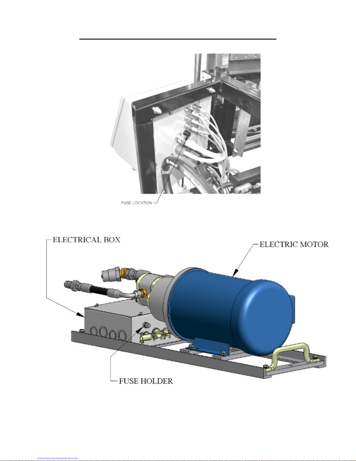
FUSES
(Figure 8)
All machines, gas or electric powered, have a 10-amp time delay fuse inside the Electrical
Control Panel Assembly. This fuse protects the electrical components. If the fuse is blown,
you will lose all functions of the machine except Motor Start. To replace this fuse: Loosen
all 4 cover screws and open the front panel of the Control Box. Locate the automotive style inline fuse near the bottom right hand corner. It is a spring loaded twist lock holder. Push
together and turn to open. Check the fuse with a continuity tester. If it is bad, replace with a
new fuse and re-connect spring loaded holder.
ELECTRIC MOTOR MACHINES
(Figure 9)
Electric motor machines have an additional 10-amp time delay fuse protecting the logic circuit
of the Contactor Box. This fuse holder is mounted in the side or top cover of the contactor box
located approximately mid machine on the right side. Access can be gained by removing the
center left side cover. This is a panel mounted, spring loaded fuse holder. To replace this
fuse: Push in on the cap and turn counterclockwise to release fuse. Check fuse with a
continuity tester. If the fuse is bad replace with a new fuse. To re-install, insert fuse into cap.
Install fuse and cap assembly into receptacle, push down and turn clockwise to lock in place.
11
Page 17
CHAPTER 5
ELECTRICAL CONTROLS AND OPERATION
Figure 5: Controls
12
Page 18
CHAPTER 5
ELECTRICAL CONTROLS AND OPERATION
Figure 6: Main Control Cable
13
Page 19
CHAPTER 5
ELECTRICAL CONTROLS AND OPERATION
Figure 7: Run Out Table and Remote Limit Switch
14
Page 20
CHAPTER 5
ELECTRICAL CONTROLS AND OPERATION
Figure 8: Main Control Box Fuse
Figure 9: QCPP E 1-6 Fuse Location
15
Page 21

CHAPTER 6
REEL STANDS, REELS, AND EXPANABLE ARBORS
REEL STANDS, REELS AND EXPANDABLE ARBORS
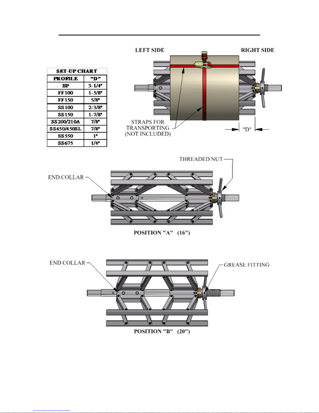
EXPANDABLE ARBOR
(Figure 10)
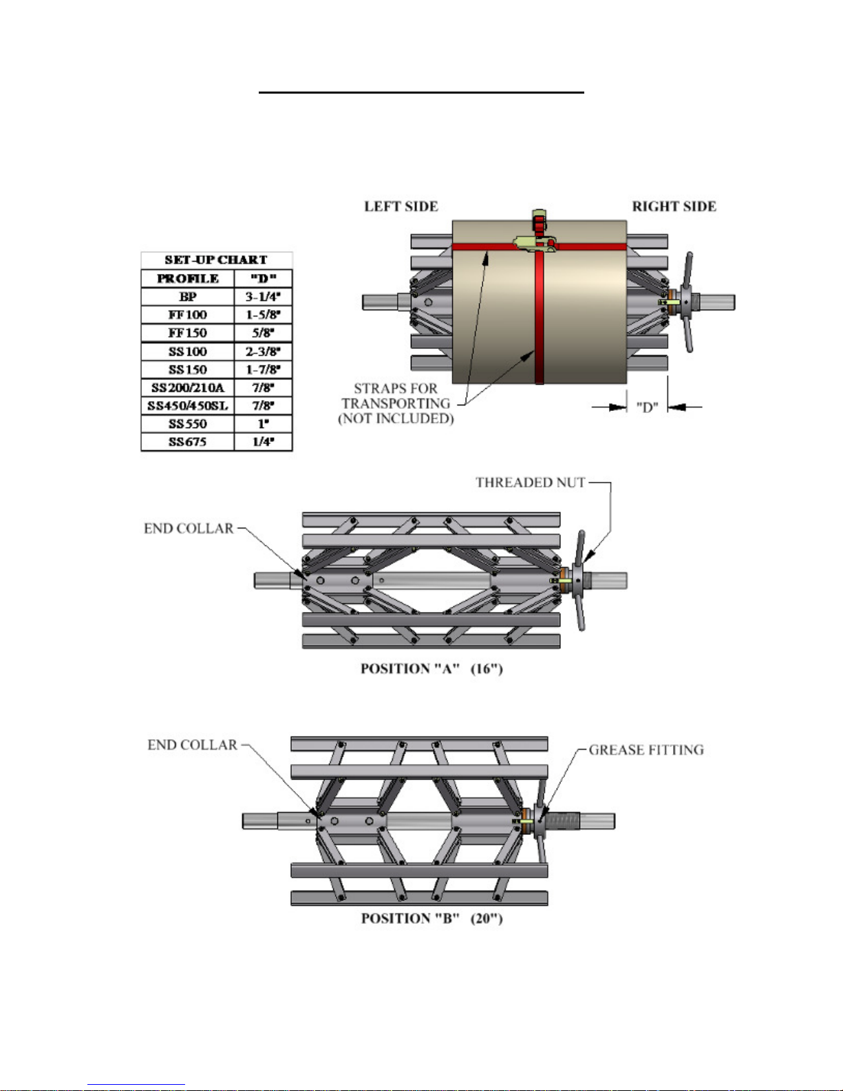
The Expandable Arbor adjusts to accommodate coils with 16” to 20” inside diameters by expanding
into the ID of the coil.
THREADED NUT
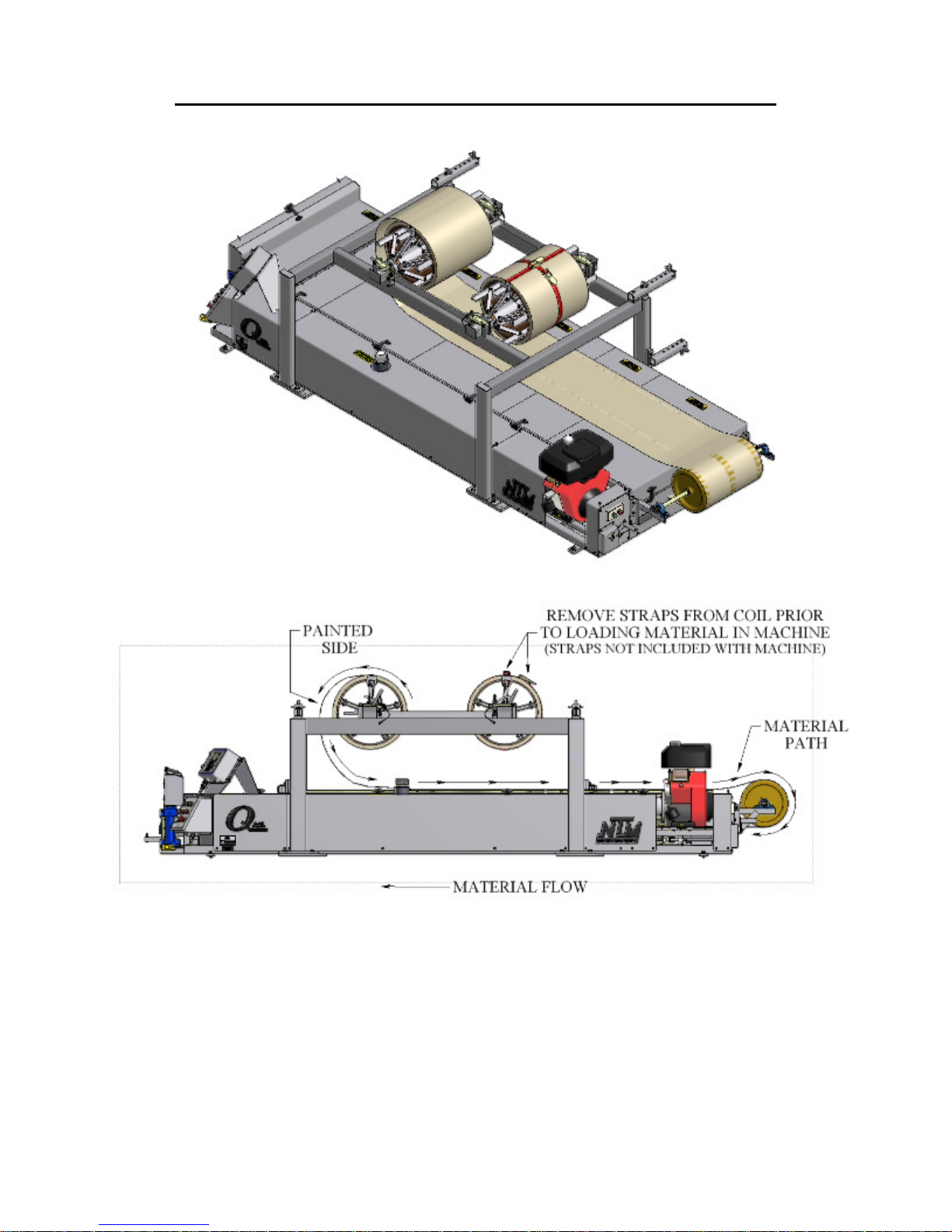
The threaded nut should always be on the right side of the machine and the tail of the coil should
always be routed over the top and pointing toward the exit or shear end of the machine.
This threaded nut is used to increase or decrease the outside diameter of the arbor. Turning the nut
clockwise will increase the outside diameter of the arbor, and counter-clockwise rotation will
decrease the arbor size. There is a grease zerk in the collar of the threaded nut that should be
lubricated at least twice a year, or whenever grease in not visible on the threads of the shaft.
END COLLAR
The End Collar has two positions.
Position “A” is used for coils with inside diameters of 16”.
Position “B” is used for coils with inside diameters of 20”.
To adjust from one position to the other, remove 2 screws “C” until end collar is free to slide. Slide
it to the inside position for 20” ID or outside position for 16” ID coil. Align it to the respective
threaded holes in the reel shaft. Re-insert and tighten "C" bolts to lock the end collar to the shaft.
LOADING EXPANDABLE ARBORS WITH COIL
1. Using the Threaded Nut, collapse the arbor small enough to fit into the inside diameter of
the coil.
2. Slide the Expandable Arbor into the center of the coil making sure the threaded nut is on the
right and the tail of the coil is over the top and pointed toward the exit end of the machine.
3. Turn the Threaded Nut clockwise until the Support Bars on the arbor are just snug against
the inside of the coil.
4. Using the Reel Set Up Chart, (Figure 10), find the “D” dimension that corresponds to the
profile you are using.
5. Slide the arbor left or right to get the correct “D” dimension measuring from the edge of the
coil to the end of the Support Bar on the Threaded Nut side.
6. Finish by rotating the Threaded Nut clockwise until the Support Bars are very tight against
the inside of the coil. Verify that dimension “D” is correct, and re-adjust if necessary. The
Coil and Arbor are now ready for loading. (see LOADING REELED COIL on page 20)
16
Page 22
CHAPTER 6
REEL STANDS, REELS, AND EXPANABLE ARBORS
Figure 10: Expandable Arbor Set-Up
17
Page 23

CHAPTER 6
REEL STANDS, REELS, AND EXPANABLE ARBORS
CAUTION: Always use properly rated lifting devices to load and unload coils.
Maximum Capacity / Reel: 3,000 lbs.
Total Capacity for Reel Stand: 6,000 lbs.
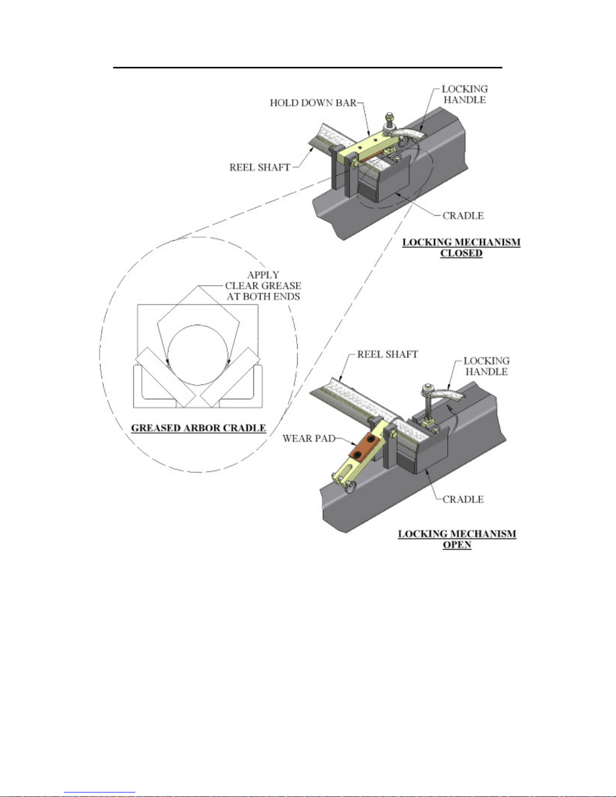
1. The reel shafts must rest in the cradles on the reel rack. Keep the cradles lubricated with
synthetic lube to minimize wear. (Figure 11)
2. Use the Hold Down Bars on each cradle to secure the coil and reel to the reel stand during
both operation and transit of the machine. The Hold Down Bracket should be used to keep
the coil from uncoiling too fast during the fabrication of panels. Apply just enough drag to
keep coil tensioned. (Figure 11)
Caution: Do not over tighten Hold Down Bars during machine operation. This will
cause excessive load on the drive and electrical systems and premature failure will result.
Do tighten Hold Down Bars tightly prior to transport of the machine.
3. If a Remote Decoiler is used it should be placed 8 to 10 feet behind the machine. Align it as
close as possible to the Right Side Entry Guide line of fire, making the side of the coil and
reel parallel to the machine. NOTE: The closer the Decoiler and reel are set to the machine,
the more critical this alignment becomes.
18
Page 24
CHAPTER 6
REEL STANDS, REELS, AND EXPANABLE ARBORS
Figure 11: Expandable Reel Assembly
19
Page 25

CHAPTER 6
REEL STANDS, REELS, AND EXPANABLE ARBORS
LOADING REELED COIL
Caution:
Always use a forklift or other approved lifting device to load or unload Fixed Reels or
Expandable Arbors loaded with coil.
The Lifting Holes in the Fixed Reel sides are provided to make loading safer and easier.
DO NOT use lifting straps through the lifting holes as the sharp edges may cut the straps.
1. Prepare the reel stand by making sure the Hold Down Bars are in the unlocked and open
Position (Figure 11).
2. Using an approved lifting device, lift the reeled coil into the cradles on the reel stand making
sure that the tail of the coil is in the correct position (Figure 12) then remove the lifting device.
3. Rotate the Hold Down Bars (Figure 11) to the closed position and thread the handle onto the
hold down bolt. If you are going to run panel from this coil, tighten the left and right handle
just snug. Final adjustment of tension should be made while running a panel to keep reel from
unwinding material too fast. As the coil becomes smaller, re-adjustment will need to be made.
Caution: Do Not over tighten Hold Down Bars. Drive and/or electrical system failure
may occur.
4. If you are going to transport the machine after loading coil, tighten the Hold Down Bars
securely to keep coil from unwinding during transport, and secure the loose end of the material
to the coil.
5. Before transporting the loaded Expandable Arbor, you should also secure the coil around the
outside edges through the inside diameter using a strap, rope, etc. to prevent the coil from
telescoping (Figure 10).
NOTE: Make sure Hold Down Bars are tightened securely and coil is properly tied off
before transporting machine.
20
Page 26
CHAPTER 6
REEL STANDS, REELS, AND EXPANABLE ARBORS
Figure 12: Material Routing
21
Page 27

CHAPTER 7
HYDRAULIC SYSTEMS
HYDRAULIC SYSTEMS
Maintenance
(Figure 13)
The hydraulic system for your machine is a very durable and reliable system. It must be
properly maintained to ensure trouble free operation and longevity. The factory has installed a 32
weight AW hydraulic fluid. Because this equipment is used primarily outdoors and exposed to the
elements, it is recommended that the oil be changed annually. Hydraulic oil will degrade if it
remains stagnate in the system for long periods of time. Check the fluid level weekly. It should be
approximately 5” below the top of the filler neck. When checking the fluid level, also note the color
and condition of the fluid. It should be clear in color.
Hydraulic Fluid Troubleshooting
CONDITION SOLUTION
1 White milky color indicates water contamination. Change the fluid.
2 Dark fluid usually indicates a dirty oil filter. Replace the oil filter.
3 Foamy fluid will cause a noisy pump and slow erratic
operation of the system. The cause is usually low oil
level or air in the system.
4 Machine runs slow after continuous operation. Check
hydraulic fluid temperature, it should be no more than
140°F (60°C).
Check fluid level and bleed off air
by pushing the shear down button
and holding for 10 seconds.
Allow to cool down. Move to a
shaded area if possible.
Changing Hydraulic Fluid and Filter
(Figure 14 & Figure 15)
The hydraulic fluid should be changed at least once a year. More frequently if the machine is
constantly in operation in a dusty environment or if the fluid becomes contaminated. To change the
fluid:
1. Remove the Left Side Covers and set aside.
2. Locate the Drain Hose “A” coiled up behind the Hydraulic Filter “B” and the Drain Valve
“C” located on the bottom of the Hydraulic Tank “D” on the Filter end of the tank.
3. Remove Filler Cap.
4. Uncoil Drain Hose and hang over the side of the machine and trailer.
5. Place a container under the hose to catch the old fluid.
6. Open the Drain Valve and drain the fluid into the container. Discard of Properly.
7. Loosen, remove and discard the used Hydraulic Filter.
22
Page 28
CHAPTER 7
HYDRAULIC SYSTEMS
8. Re-install the new hydraulic filter and fill the tank with fresh 32 weight fluid until it is 5”
below the top of the Filler Neck “F” (approximately 18 gal).
Figure 13: Hydraulic System – Overview
23
Page 29
CHAPTER 7
HYDRAULIC SYSTEMS
Figure 14: Hydraulic System – Details
24
Page 30
CHAPTER 7
HYDRAULIC SYSTEMS
Figure 15: Hydraulic Fluid Level
25
Page 31

CHAPTER 8
DRIVE SYSTEM
DRIVE SYSTEM
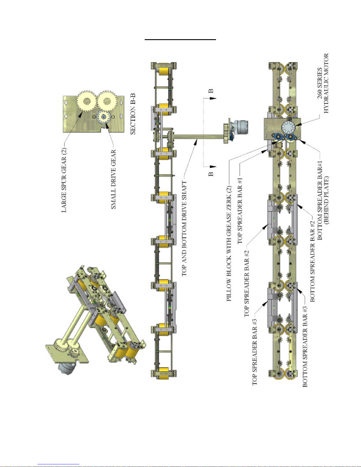
(Figure 16, Figure 17 & Figure 18)
The drive system of your machine consists of eight top and eight bottom polyurethane drive rollers.
They are divided into groups of 2 per assembly making 4 Top Drive Roll Assemblies and 4 Bottom
Drive Roll Assemblies. They are connected together via chain and sprocket and there are chain
tensioner’s on each assembly. The drive system is powered by a hydraulic motor which transfers
power to the drive assemblies using spur gears and a top and bottom drive shaft.
1. Clearance between the top and bottom drive rollers is factory set at ¾ of a turn of
pressure past the point of contact. This will drive material up to 22ga. though the
machine without the need for adjustment. If adjustment becomes necessary due to
slippage, you can add pressure. Do not add more than ¼ turn beyond the factory
setting. It is important to adjust only one end of each assembly at a time to maintain side
to side alignments.
To add pressure: Loosen two Lock-Down Bolts “B” 1/8 of a turn. Loosen lock nuts on
two corresponding Jack Bolts “A”. Tighten Bolts “A” 1/8 of a turn. Re-tighten 2 lock
nuts on Jack Bolts “A” to lock in adjustment. Repeat this procedure on the other end of
the Drive Assembly and repeat for the other 3 drive assemblies. Test for result and
repeat one more time if necessary.
To remove pressure: Loosen two lock nuts on Jack Bolts “A”. Loosen two Jack Bolts
“A” 1/8 of a turn. Tighten two corresponding Lock-Down Bolts “B” 1/8 of a turn.
Tighten two lock nuts on Jack Bolts “A” to lock in adjustment. Repeat this procedure on
the other end of the Drive assembly.
2. There are three different chain tensioners on your machine.
A. The first are located in slots on the side plates of the Drive Roll Assemblies. They
follow the chain locations alternating from one side to the other. To adjust, slightly
loosen the nut on the bolt holding the tensioner sprocket in place. Using a dead blow
hammer tap the tensioner assembly toward the drive roller until the chain is snug.
Lock into position by tightening the bolt on the assembly.
B. The second type is similar. These are located on the top and bottom spreader bars
located between the Drive Roll Assemblies. These are used in the same way except
there is a bolt located in the edge of the slot on the assembly used to push the
tensioner assembly toward the Drive Roller to tension the chain.
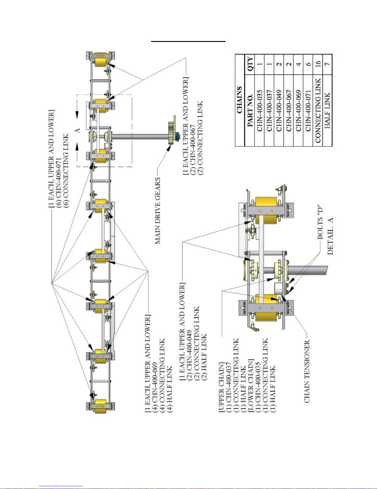
C. The third is located on the Top #1 Spreader Bar between the sprocket and drive
roller. (see detail ‘A” Figure 18) Loosen two “D” bolts enough so that you can move
the tensioner assembly up toward the chain until snug. Re-tighten the two “D” bolts.
3. The chains used in this system are #50 Roller Chain. See Figure 18for chain locations
and lengths if chain replacement is necessary.
4. The polyurethane drive rollers will eventually need cleaning. This will become evident
when they start leaving a stripe the width of the drive roller on the formed panels that
doesn’t come off easily or if you run material with an oily film on it. Avoid cleaning the
drive rollers with harsh chemicals or solvent. These products will attack the
polyurethane and cause irreversible damage. Use of these products will void the
warranty on the drive rollers.
26
Page 32
CHAPTER 8
DRIVE SYSTEM
Clean the rollers with mild soap and water and a rag. Caution must be taken around
the moving parts of the machine during the cleaning process.
5. Covers should be kept on the machine during operation and storage. Ultraviolet light
will attack the polyurethane drive rollers and cause deterioration. Again, this type of
damage is not covered under the warranty.
Figure 16: Drive Roll Assembly View
27
Page 33
CHAPTER 8
DRIVE SYSTEM
Figure 17: Gears and Shafts
28
Page 34
CHAPTER 8
DRIVE SYSTEM
Figure 18: Chains Upper and Lower
29
Page 35

CHAPTER 9
SHEAR ASSEMBLY
SHEAR ASSEMBLY
OPERATION
Push the SHEAR DOWN button to activate the shear cycle and cut material. IN CASE OF
AN EMERGENCY: Push the SHEAR UP button during the down cycle to immediately
send the shear up to the home position.
The shear is electrically activated and hydraulically driven.
The two Top Limit Switches and single Bottom Pressure Switch control the cycle of the shear.
The Top Limit Switches electronically lock out the drive system when the shear is in motion.
The Bottom Pressure Switch sends the shear back up once the set pressure is reached.
SHEAR ADJUSTMENTS
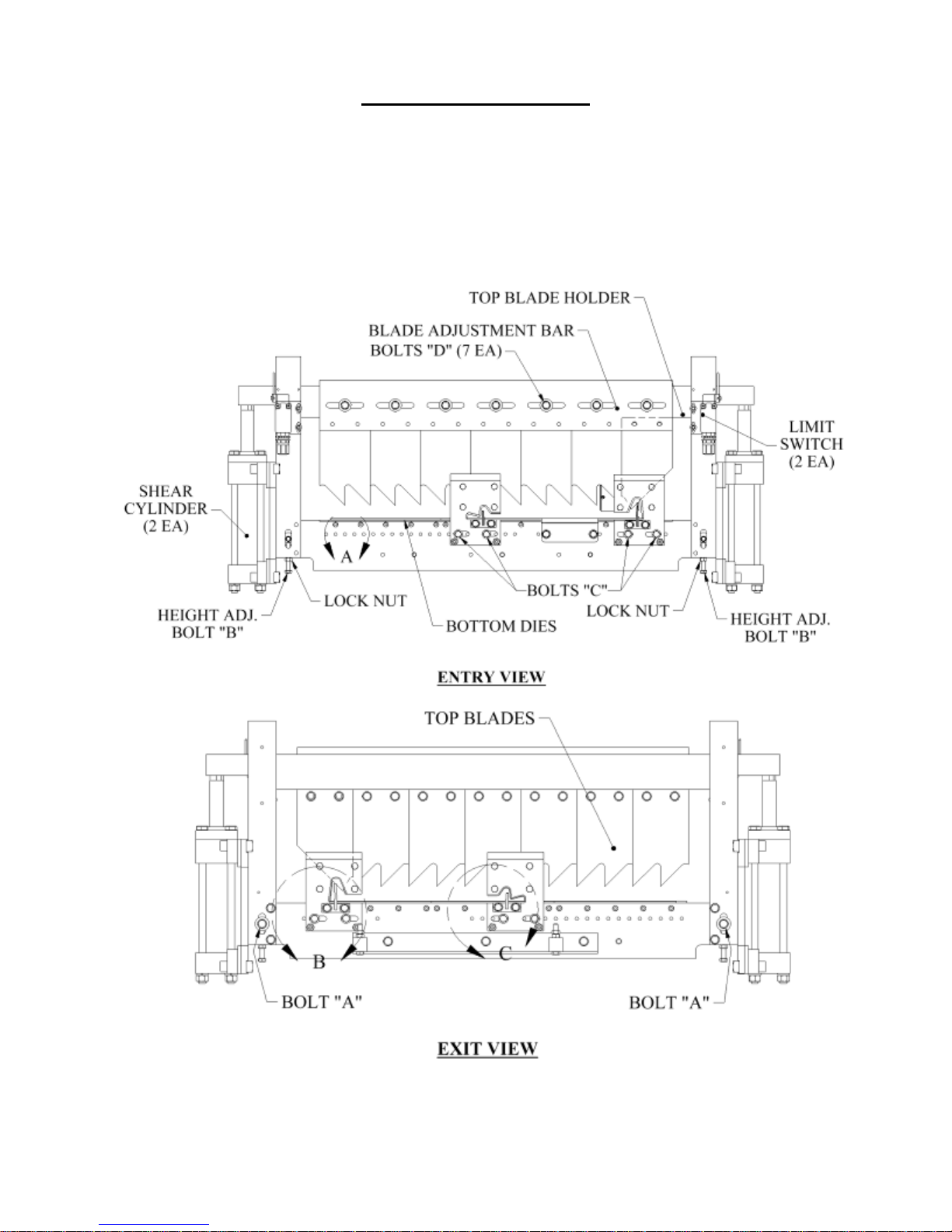
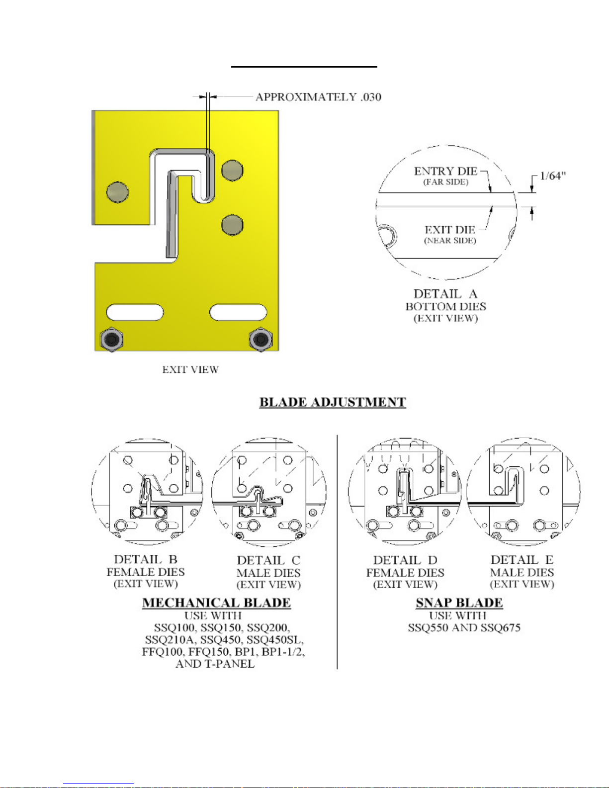
Bottom Shear Dies (Detail A - Figure 20)
1. Bottom dies should be adjusted 1/32” below the bottom corners of the panel. Loosen the (2)
“A” bolts on the left and right Front Vertical Plates. Loosen the (2) lock nuts on the (2)
Height Adjustment bolts “B”.
2. Tightening bolts “B” will lower the shear, and loosening them will raise it. Adjust each side
as needed to properly set the bottom dies to the correct spacing from the bottom corners of
the panel.
3. After adjustments have been made, tighten (2) “A” bolts and (2) Lock Nuts on Height
Adjustment Bolts “B”.
CHANGING ENTRY AND EXIT SHEAR DIES
(Figure 19 & Figure 20)
The Entry and Exit Shear Dies are specific to each roller set and must be changed when changing
profiles. Refer to the PROFILE CHANGEOVER PROCEDURE for instruction on changing dies.
ADJUSTING THE ENTRY AND EXIT SHEAR DIES
(Figure 19 & Figure 20)
1. The Male and Female entry and Exit Shear Dies must be adjusted to the proper distance from
the vertical legs of the panel. The outside vertical leg of the male and female Entry Dies
should be approximately 1/32” away from the outside of the vertical legs of the panel. The
Exit Dies should be slightly to the outside of the male and female Entry Dies so that after a cut
is made, the panel does not hang up on the Exit Dies.
2. Each Shear Die Holder is held in position by (2) “C” bolts passing through slotted holes at the
bottom edge of the holder, and threaded into the Entry and Exit Shear Plates.
3. Visually sight thru the male and female entry dies. Rough align them to the forming tool “line
of fire” by moving them side-to-side. If necessary, remove bolts “C” and slide the Die
Holders left or right until you find two mounting holes that will work for proper alignment,
then re-install bolts “C”. Tighten them just enough to hold the dies in position.
4. Jog the material through the machine and stop about 2 inches from the Entry Shear Dies.
Now re-sight the alignment of the Male and Female Dies to the actual legs of the panel and
move them accordingly to assure the panel will pass through without hanging up. Carefully
jog material through the shear dies. Final adjust Entry and Exit Dies as follows: The Male
30
Page 36
CHAPTER 9
SHEAR ASSEMBLY
and Female Entry Dies should be 1/32” or less away from the back side of the vertical leg of
the panel. The Male and Female Exit Dies should be adjusted slightly to the outside of the
entry dies so that the cut edge of the panel clears the dies without interference when passing
through after a cut. Once alignment of the dies is achieved, tighten all “C” bolts. Jog the
material out approximately 2”. Engage the shear to cut to 2” piece off. Inspect the cut made on
this piece and the piece still in the machine by jogging it out another 2” so it can be viewed. If
the cut is not satisfactory, re-adjust as necessary.
Figure 19: Entry/Exit Views
31
Page 37
CHAPTER 9
SHEAR ASSEMBLY
Figure 20: Shear Die Detail Views
32
Page 38

CHAPTER 9
SHEAR ASSEMBLY
TOP SHEAR BLADE ADJUSTMENT
(Figure 19 & Figure 20 – Details B & C)
The Top Shear Blades are bolted to the Blade Adjustment Bar. This bar is bolted to the Top Blade
Holder, and can be moved from left to right to align the blades to the Die Holders.
1. Loosen the 7 “D” bolts in the slots at the top entry side of the shear so that the Blade
Adjustment Bar will move from side to side.
2. The point of the Top #1 Blade should always be inboard of the Female vertical leg of the
panel, and should not pierce the top horizontal leg of the profile. The rake or angle of the
blade should cut in a scissor action outward against the leg. The #2 Top Blade must be
adjusted simultaneously in the same manner for the Male leg. You should be able to find a
position that works for both Male and Female legs. Once the Blade Adjustment Bar is in the
correct location, tighten all “D” bolts.
3. Jog the panel out approximately 12” and make the first cut. Check the piece to make sure the
cut is acceptable. Carefully jog the material through the shear dies making sure the panel does
not get caught on the Male or Female exit dies. If the panel gets caught on the exit dies, fine
tune the adjustment of the dies to correct the problem following the procedures above.
MAINTENANCE
1. Clean and lubricate the Top Blades, Bottom Dies, and Male/ Female dies at least once a day
during normal use, or whenever cutting surfaces look dry. Proper lubrication is essential to
clean cuts, rust prevention and longevity.
Super Lube - Multi-Purpose Synthetic Dri Film Aerosol Lubricant with Syncolon (PTFE)
Catalog No. 11016
11 oz. Aerosol Can
Available from:
MSC Supply at 1-800-645-7270
33
Page 39

CHAPTER 10
BEAD AND STRIATION ROLLER ASSEMBLY
BEAD AND STRIATION ROLLER ASSEMBLY
1. The Bead / Striation Roller assembly (Figure 21) is located behind the shear and
is accessed by removing top cover #3. These rollers can be engaged or
disengaged as needed and can also be moved left or right to accommodate
different panel widths.
2. The bottom bead or striation forming roller should be set 1 /32” above the drive
roller to ensure proper entry into the shear. If adjustment is necessary, loosen
the four frame mount bolts “B”, and lock nuts on the two vertical adjustment
bolts “A”. Raise or lower the roller assembly by using the vertical adjustment
bolts “A” to obtain the proper height. Then re-tighten the mount bolts and lock
nuts on the two adjustment screws “A”.
3. Next loosen the eccentric shaft lock down screw “C”. Place a 5/32” Allen
Wrench in the small hole at the end of the eccentric shaft, and rotate the top
roller up until it clears the bottom roller. Loosen the two top and two bottom
slide lock down screws “D”. Bring the panel material up to the rollers but not
past them. SHUT OFF THE MACHINE AND DISCONNECT THE
POWER BEFORE CONTINUING. Locate the bottom rollers to the desired
position by sliding the assembly on the bottom slide bars. Tighten the bottom
slide lock-down screws ”D”. Restart the machine and back up the panel until
you gain access to the top slide lock-down screws, AGAIN SHUT OFF THE
MACHINE AND DISCONNECT THE POWER. Loosen the top slide lockdown screws, and slide them into position so the top roller is directly over the
bottom roller. Tighten the top slide lock-down screws “D”. Next rotate the
eccentric shaft down to the desired bead depth. DO NOT go below .045”
minimum clearance; excessive bead depth will distort your panel. Re-tighten
screws “C”.
4. Keep slide bars lightly greased to allow bead or striation assemblies to slide
smoothly.
34
Page 40
CHAPTER 10
BEAD AND STRIATION ROLLER ASSEMBLY
Figure 21: Bead Roller Assembly
35
Page 41
CHAPTER 11
ENTRY GUIDE ASSEMBLY
ENTRY GUIDE ADJUSTMENT
(Figure 22 & Figure 23)
The entry guides are used to set the material to the correct position in relation to the
forming rollers of the machine. They also hold the material and feed it straight into the
machine. If the entry guides are not set correctly the material will not feed into the
machine properly.
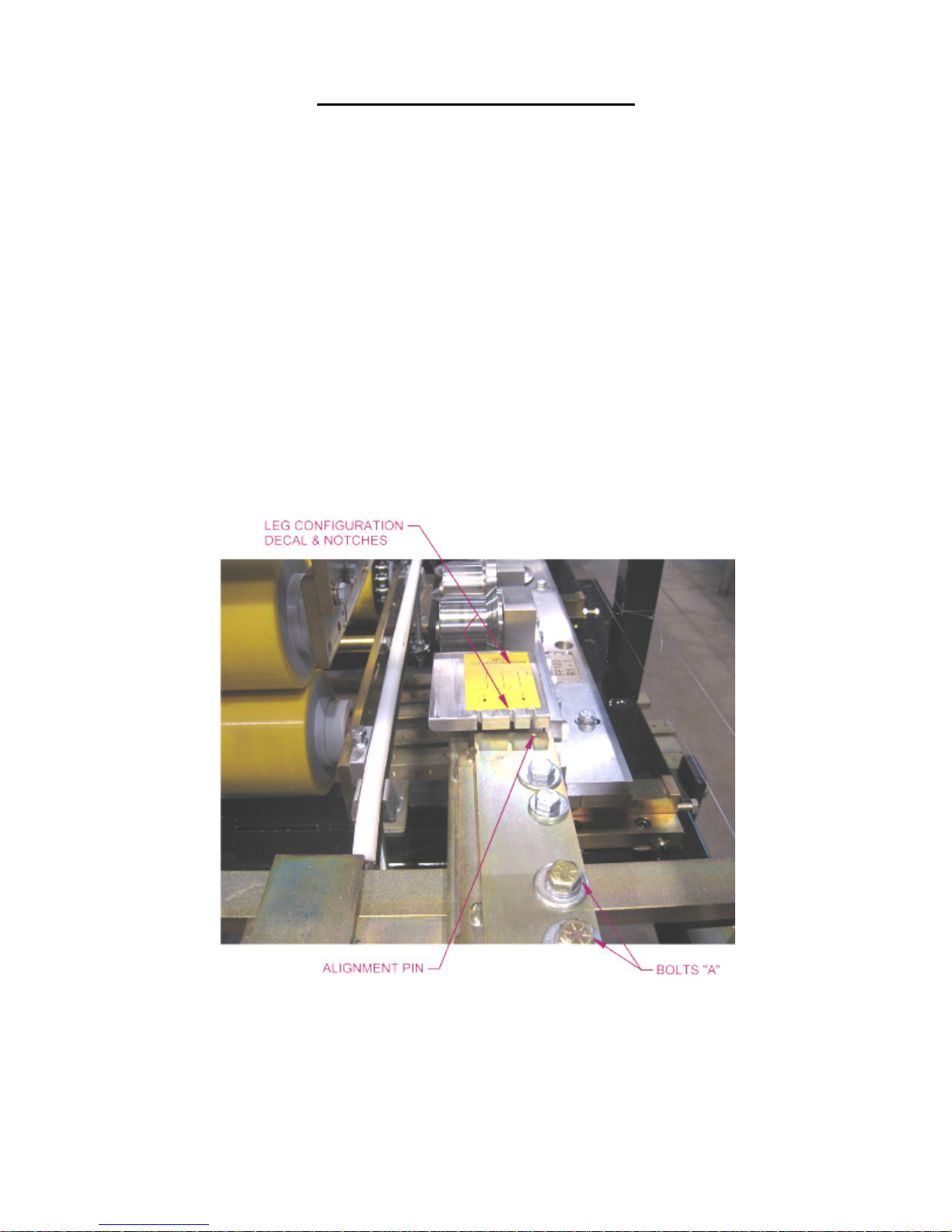
1. The Right Entry Guide is set to the Tooling Rail Marker Plate mounted to the
R1 Tooling Rail.
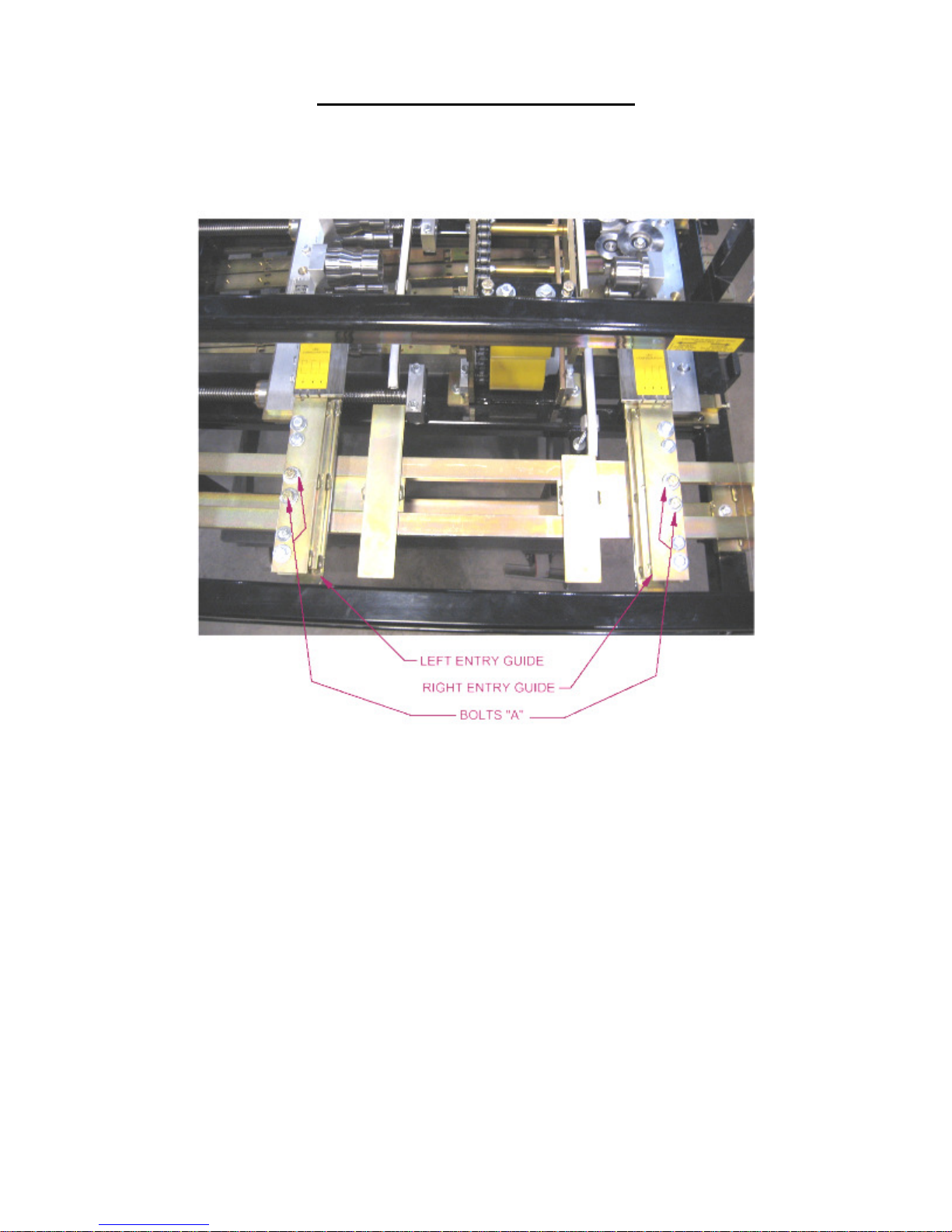
2. To align, loosen the two “A” Bolts on the Right Entry Guide. Slide the entry
guide to the left or right until the alignment pin which is located at the end of
the top shoe of the entry guide, is directly under one of the notches on the
Tooling Rail Marker Plate. Make sure to choose the notch that corresponds to
the desired leg configuration as noted on the decal on the top of the marker
plate.
3. Tighten the two “A” bolts.
4. Loosen bolt “A” on the left entry guide.
5. Cut a 12” long piece of gage material from the coil you will be using, to set the
left entry guide.
6. Slide gage material between the left and right entry guides.
Figure 22: Right Entry Guide
36
Page 42
CHAPTER 11
ENTRY GUIDE ASSEMBLY
7. Slide the Left Entry Guide to the left or right to accept the new coil width. Make
sure that the coil is captured snugly between the entry guides and re-tighten the
two “A” bolts.
Figure 23: Entry Guide Assembly
LEFT TOOLING RAIL TO ENTRY GUIDE ALIGNMENT
(Figure 24 to Figure 27)
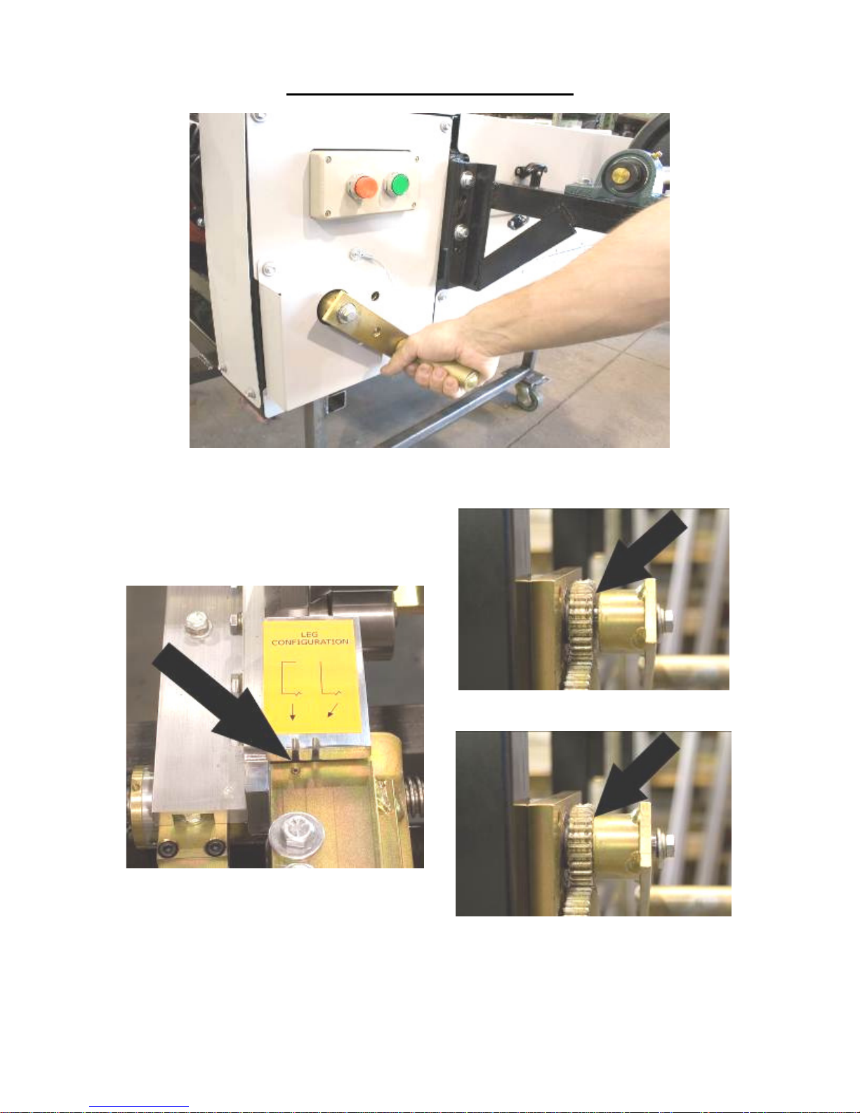
The Tooling Rail Adjustment Handle is used to move the Left Tooling Rails assemblies
to the left or right to align them to the Left Tooling Rail Marker Plate whenever a
width change or tooling change has been made.
1. Using the Tooling Rail Adjustment Handle (Figure 24) align the notch on the
tooling rail marker plate to the alignment pin located in the Left Entry Guide.
Make sure to choose the notch that corresponds to the desired leg configuration as
noted on the decal on the marker plate (Figure 25). The Tooling Rail Adjustment
Handle is spring loaded to allow it to disengage from the width adjustment gear
(Figure 26). Press the handle inward (Figure 27) to engage the width adjustment
gear and turn the handle clockwise to move the tooling outward or counterclockwise to move it inward.
37
Page 43
CHAPTER 11
ENTRY GUIDE ASSEMBLY
Figure 24: Tooling Rail Adjustment Handle
Figure 25: Marker Plate & Alignment Pin
Figure 26: Disengaged
Figure 27: Engaged
38
Page 44
CHAPTER 12
CLIP RELIEF ROLLER ASSEMBLY
CLIP RELIEF ROLLER ASSEMBLY
1. Clip Relief Rollers (Figure 28) provide a raised area next to the male and female
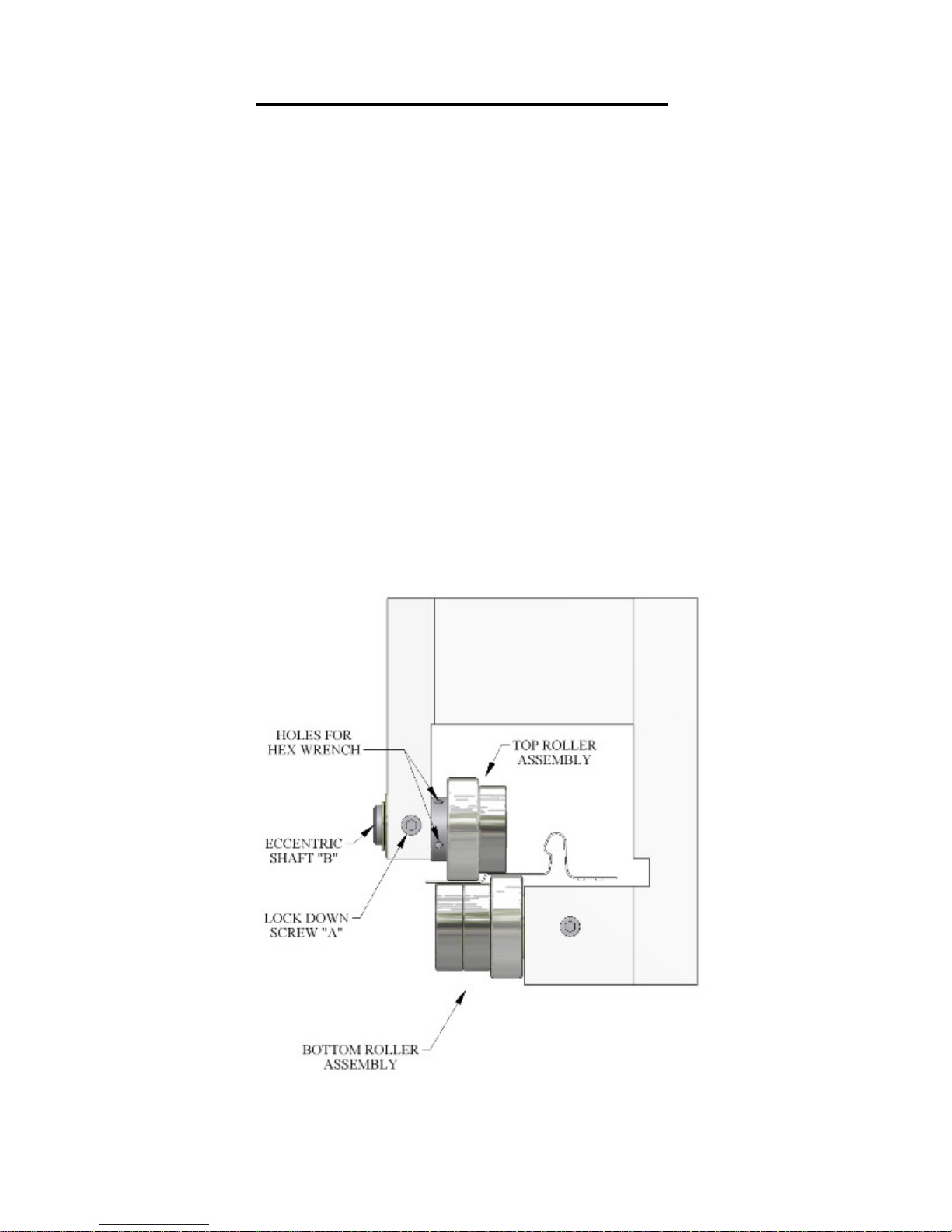
legs of the panel. This helps hide the clip and screws used in installation. They
rollers can be engaged or disengaged as needed.
2. Find the Tooling Rail Sheet corresponding to the profile installed in your machine
(Figure 59 - Figure 79).
Note the location of clip relief assembly’s on left and right tooling rails, and
locate them on the tooling set in your machine.
3. To engage the clip relief rollers loosen lock down screw “A” and insert a 5/32”
allen wrench into the small hole on the top eccentric shaft “B”.
4. Rotate the eccentric shaft to engage or disengage the top roller assembly from the
bottom roller assembly. Adjust both left and right bead assemblies to the desired
depth using a feeler gage. Recommend factory setting is 0.080 inches gap
between top and bottom rollers.
NOTE: The FF100 and FF150 profiles must always be engaged for proper
male/female lock to occur.
Figure 28: Clip Relief Roller Assembly
39
Page 45
CHAPTER 13
ENTRY DRUM ASSEMBLY
ENTRY DRUM ASSEMBLY
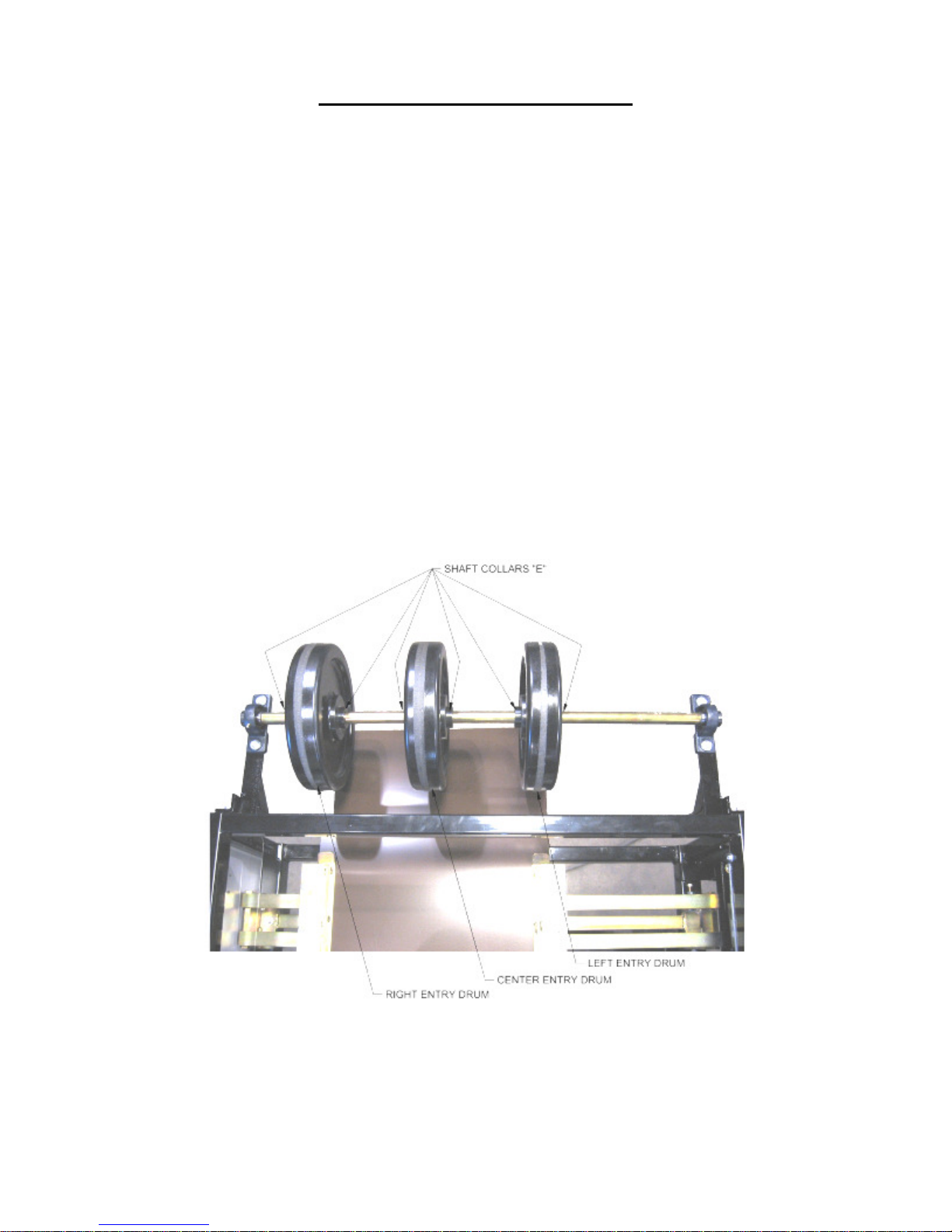
The Entry Drum Assembly is necessary when feeding coil off of the optional DR1/ Dual
Overhead Reel Stand. It allows you to route the material around the drums to get the
painted side of the coil on the top as it enters the machine. Without this assembly, you
could only feed coil from a remote arbor and stand lined up behind the machine. The
Entry Drums need to be adjusted whenever a width change is made.
To adjust the entry drums:
1. Using a 3/16” allen wrench, loosen the four Shaft Collars “E”, on either side of
Left Entry Drum and Center Entry Drum. (Figure 29)
2. Slide the Left Entry Drum over until it is lined up with left edge of the new coil
and align the Center Entry Drum equally spaced from the Left and Right Entry
Drums.
3. Slide the four Shaft Collars “E” against the sides of the drums and lock them into
place.
4. If you are making a Roller System Change, you may have to move all three drums
using the same procedure described above.
Figure 29: Entry Drum
40
Page 46
CHAPTER 14
WIDTH CHANGE PROCEDURE
WIDTH CHANGE PROCEDURE
CAUTION: Always make sure your machine is shut down prior to making any
adjustments. DO NOT reach through the opening of the shear while the machine
is running. EVER! To do so could result in serious injury.
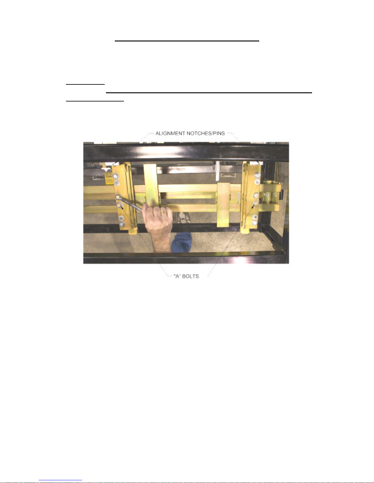
1. Loosen the two “A” bolts on the Left Entry Guide (Figure 30). Slide the entry
guide to the left or right to accept the new coil width.
Figure 30: Entry Guide Bolts "A"
2. Make sure that the coil is captured snugly between the entry guides and re-
tighten the two “A” bolts.
3. Using the Tooling Rail Adjustment Handle “B” (Figure 24) align the notch on
the tooling rail marker plate to the alignment pin located in the Left Entry
Guide. Make sure to choose the notch that corresponds to the desired leg
configuration as noted on the decal on the marker plate (Figure 25). The
Tooling Rail Adjustment Handle is spring loaded to allow it to disengage from
the width adjustment gear (Figure 26). Press inward on the center of the
handle and turn (Figure 27) to engage the width adjustment gear. Turn the
handle clockwise to move the tooling outward or counter-clockwise to move it
inward.
41
Page 47
CHAPTER 14
WIDTH CHANGE PROCEDURE
4. Load material onto the Expandable Arbor and align it to the correct position
using the chart on (Figure 31).
Note: Also see REEL STANDS, REELS AND EXPANDABLE ARBORS for
more information.
Figure 31: Expandable Arbor Setup
42
Page 48
CHAPTER 14
WIDTH CHANGE PROCEDURE
5. Load the reeled coil onto the machine using a fork lift or other rated lifting
device. Making sure the tail of the coil goes over the top and points toward the
shear end of the machine. See coil routing diagram (Figure 12).
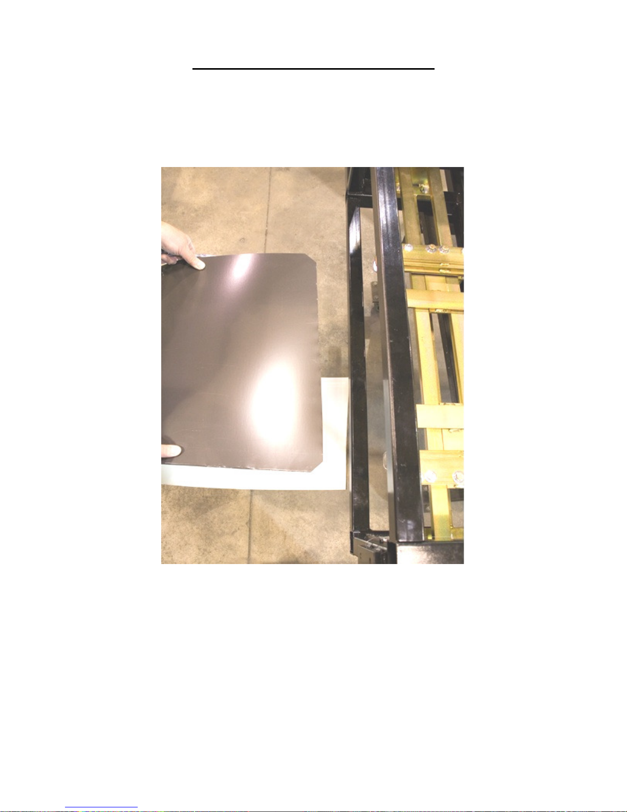
6. Cut a 1” triangle of off the 2 leading corners of the coil and feed it into the
entry guides. (Figure 32)
7. Start the machine and use the Jog button on the Manual Control Box or
Computer, to jog the material through the machine 6 to 8 inches at a time until
it exits the last forming stations, and is about 1” from the Bead Roller
Assembly. (Figure 21).
SHUT YOUR MACHINE DOWN BEFORE PROCEEDING.
Figure 32: Loading Material
43
Page 49
CHAPTER 14
WIDTH CHANGE PROCEDURE
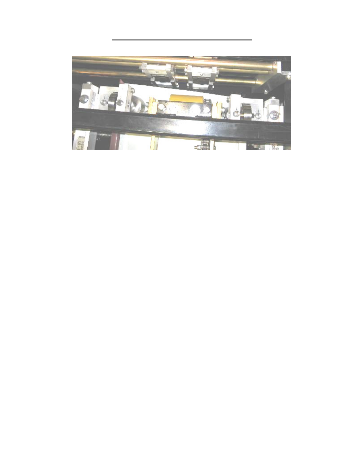
Figure 33: Bead Roller Alignment
8. If you require beads in the panel, determine the spacing needed. For Example:
a 12” wide panel with 2 beads centered on the panel would give you 3 equal
spaces or 12” divided by 3 equals 4” from center to center of each bead. Hook
the end of you tape measure on the outside bottom corner of the female leg.
Use a magic marker or grease pencil to mark the 4” and 8” locations on the
panel. You now have 3 equal spaces.
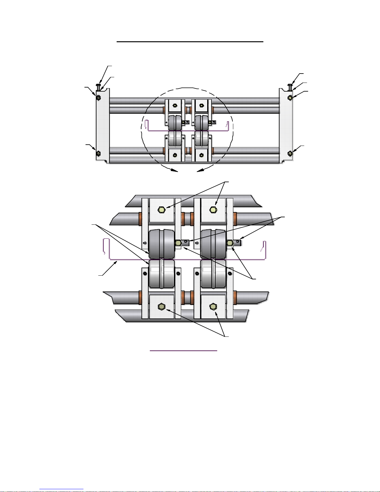
9. Loosen the slide lock bolts on the top and bottom bead assemblies (Figure 34)
and slide each bottom and top roll assembly left or right to center them on the
4” and 8” marks on the panel.
10. Lock the two top bead assemblies in the correct position by tightening the
slide lock bolt “D” on each assembly. Next align the bottom bead rollers to
the tops so that the ends of the top and bottom rollers are flush with each other
and tighten the bottom slide lock bolts on these 2 assemblies.
44
Page 50
CHAPTER 14
WIDTH CHANGE PROCEDURE
BO L T " A"
LOCK N UT
BOL T "B"
BOL T "A"
LOCK N UT
BO LT "B "
BOL T "B"
SID ES FLU SH
PAS S LIN E
BO LT "B"
A
BO LT "D"
HOLE FO R
HEX WREN CH
BO LT "C"
11. Check the gap between the top and bottom bead rollers using a feeler gauge.
An approximate setting of 1½ times the material thickness is recommended.
This setting can be adjusted slightly in either direction according to
preference.
12. To set or change the gap between top and bottom beads, loosen the "C" bolt
on both top rollers (Figure 34).
13. Insert the correct feeler gage between one of the top and bottom rollers.
Locate the feeler gage on the flat of the roller next to the side plate of the
assembly.
DETAIL A
BO LT "D"
RR5 OP TION SHOW N
Figure 34: Bead Roller Width Change
45
Page 51
CHAPTER 14
WIDTH CHANGE PROCEDURE
14. Rotate the top shaft from the 12:00 position toward the shear to decrease the
gap, or away from the shear to increase the gap until the feeler gage is
captured.
15. Tighten the “C” bolt to lock the position of the shaft.
16. Repeat steps 11through 15for the remainder of the bead rollers.
17. Start the machine, jog the material through the bead assemblies and stop 2 to 3
inches from the entry shear dies.
18. Inspect the beads for depth and re-adjust as necessary.
CAUTION: SHUT THE MACHINE OFF BEFORE PROCEEDING.
19. Start the machine and jog the material through the bead assemblies and stop 2
to 3 inches from the entry shear dies
SHUT THE MACHINE OFF AGAIN BEFORE PROCEEDING.
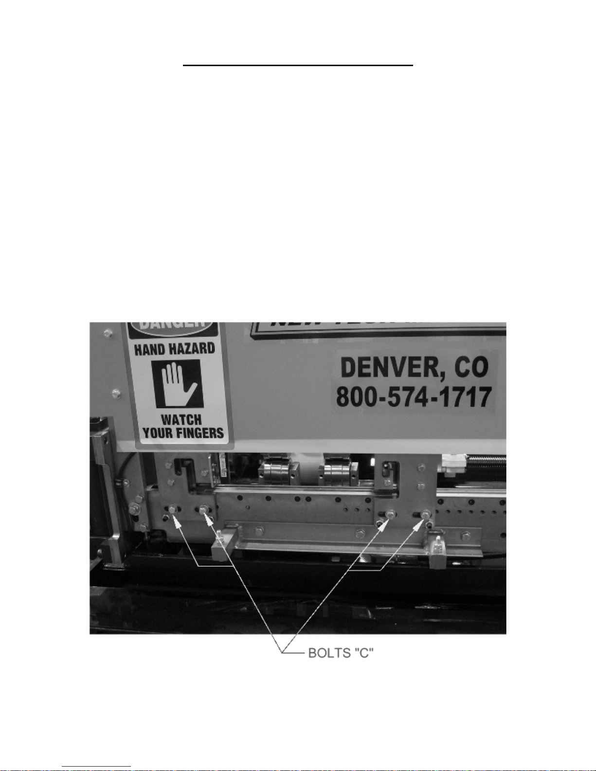
20. Remove the two “C” bolts located in the slotted holes at the bottom edge of
the exit male shear die assembly and set the bolts and assembly aside. (Figure
35)
21. Remove the two “C” bolts in the slotted holes on the entry male shear die
assembly.
Figure 35: Shear Bolts
46
Page 52
CHAPTER 14
WIDTH CHANGE PROCEDURE
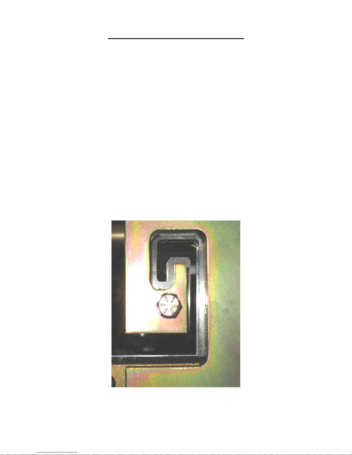
22. Visually site through the male entry die and rough align it to the forming tool
“line of fire” by sliding it left or right. Re-install the two “C” bolts into holes
that correspond to the slots. Do not tighten the bolts at this time, just snug
them up.
23. Install the male exit die in the same manner aligning it to the entry die and
again, just snug the bolts.
24. Start the machine and carefully jog the panel up to the shear. Check to see if
the panel will pass through the entry shear die. If not FIRST SHUT THE
MACHINE OFF, then move the entry die so that the panel will pass through
it.
Adjust the entry die so that it is as close to the outside vertical portion of the leg
as possible without touching it. Once this is done, tighten the two “C” bolts on the
entry male shear die assembly.
25. Check the exit shear die to ensure that the material will pass through it. If not
adjust as necessary.
26. Start the machine again and slowly jog the panel approximately 6” past the
exit male shear die assembly and stop. Again, TURN THE MACHINE OFF.
27. Adjust the exit male shear die assembly so that it is offset to the outside of the
entry die by approximately 1/64” and lock down the two “C” bolts (Figure 36)
This offset is necessary so that after a cut is made, the leading edge of the
panel does not hang up on the exit die.
28. Look down the leg of the panel and make sure that the entry and exit male
shear die assemblies are not touching the panel as it passes through them.
Figure 36: Exit Die Adjustment
47
Page 53

CHAPTER 14
WIDTH CHANGE PROCEDURE
29. Make sure that one of the points of the top shear blade is inboard of the
vertical portion of the male leg. This part of the leg should be cut with the
angle or rake of the blade to cut in a scissor action against the vertical die. See
TOP SHEAR BLADE ADJUSTMENT (Figure 19 & Figure 20) if
adjustment is necessary.
30. Start the machine and press the shear down button to cut off the panel, then
jog the material through the shear again and stop.
31. Inspect the two cuts and adjust the dies as necessary until an acceptable cut is
made. Again, TURN THE MACHINE OFF BEFORE MAKING ANY
ADJUSTMENTS.
32. Once you are satisfied with the cut being made, you are ready to run panel.
48
Page 54
CHAPTER 15
PROFILE CHANGEOVER PROCEDURE
PROFILE CHANGEOVER PROCEDURE
CAUTION: Always make sure your machine is shut down prior to making any
adjustments. DO NOT reach through the opening of the shear while the
machine is running. EVER! To do so could result in serious injury.
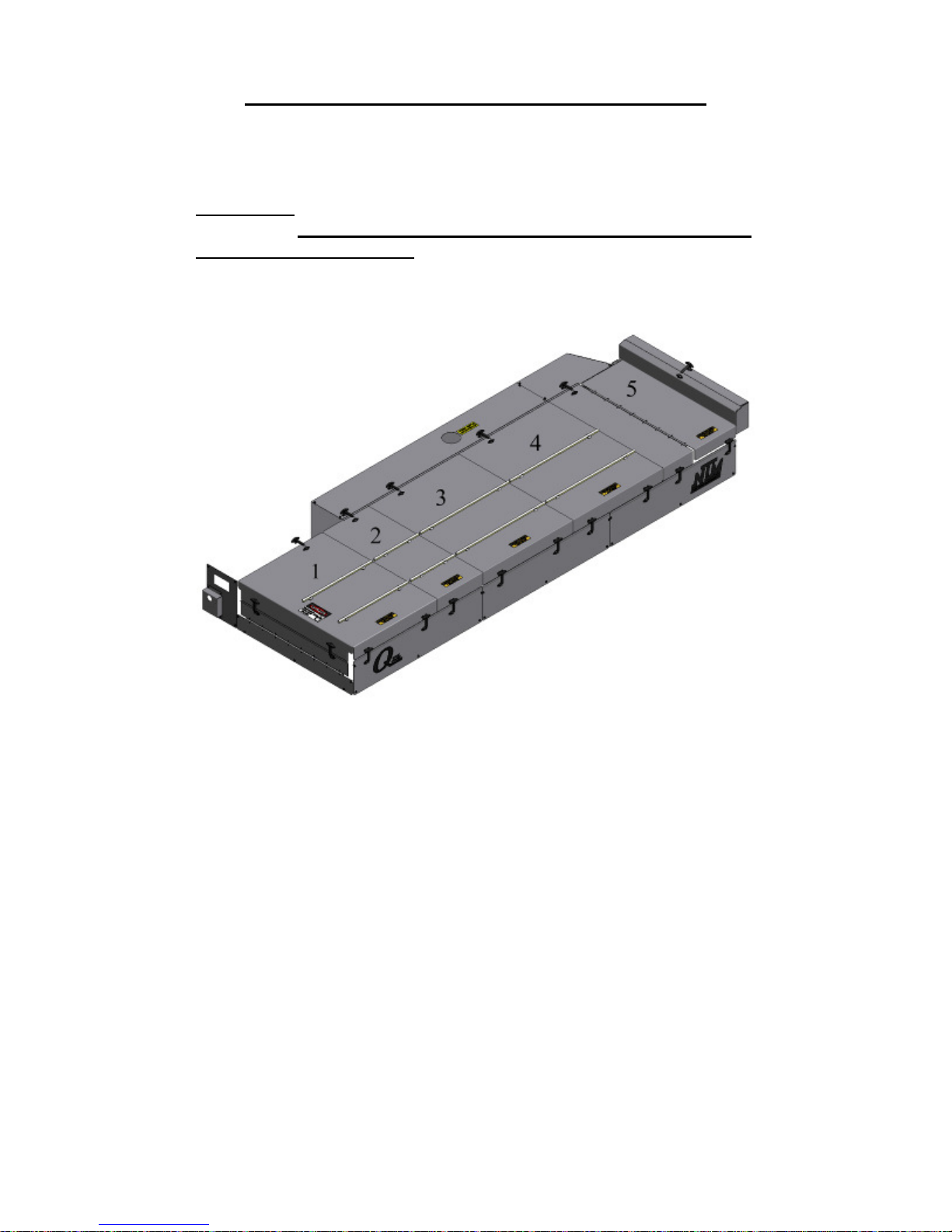
1. Remove Top Covers number 1, 2, 3, 4, and 5 (Figure 37) and set aside.
Figure 37: Remove Top Covers
2. Using a ½” wrench, remove the bolts holding the right and left Tooling Rails to
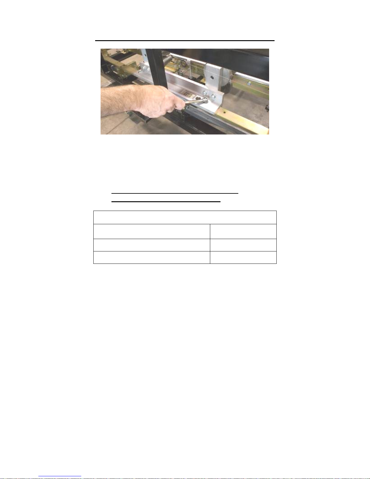
the Fixed Rail Mounts (Figure 38). Store the tooling and set the hardware near the
machine for use when installing the next profile. Note: the SS100, SS150,
SS450/450SL, and BP profiles all share the same left-side rollers, so if you are
changing from one of these profiles to another you will only need to remove the
right-side Tooling Rails. Likewise, the FF100 and FF150 profiles also share the
same left-side rollers, so if you are changing between these two profiles you will
only need to remove the right-side Tooling Rails.
49
Page 55
CHAPTER 15
PROFILE CHANGEOVER PROCEDURE
Figure 38: Removing Tooling Rails
3. Refer to the SSQ Slide Block chart (Figure 39) and find the profile you will be
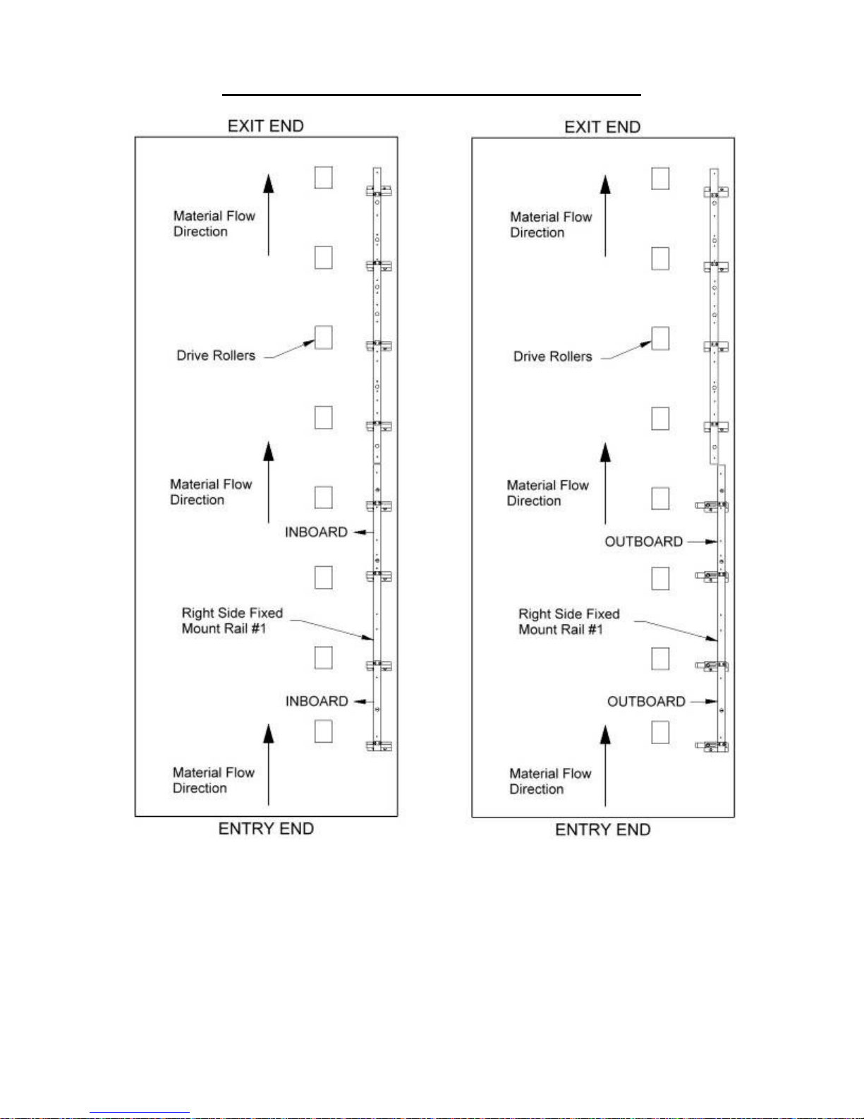
installing into the machine. It will tell you if the Right Side Fixed Mount Rail #1
needs to be in the Inboard position or Outboard position (Figure 40).
IF THE RAIL IS NOT IN THE CORRECT POSITION, GO TO STEP 4.
IF THE RAIL IS IN THE CORRECT POSITION GO TO STEP 6.
SSQ SLIDE BLOCK CHART
PROFILE
BP, FF100, SS100, SS150 INBOARD
FF150, SS200, SS450, SS550, SS675 OUTBOARD
Figure 39: Block Chart
RIGHT SIDE FIXED
MOUNT RAIL #1
50
Page 56
CHAPTER 15
PROFILE CHANGEOVER PROCEDURE
Figure 40: Inboard/Outboard Positions
51
Page 57
CHAPTER 15
PROFILE CHANGEOVER PROCEDURE
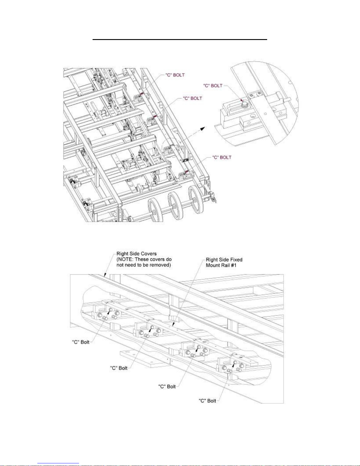
4. Loosen bolt “C” on the first 4 Slide Block assemblies (Figure 41 or Figure 42).
Figure 41: April 2009 and later
Figure 42: Machines made before April 2009
52
Page 58
CHAPTER 15
PROFILE CHANGEOVER PROCEDURE
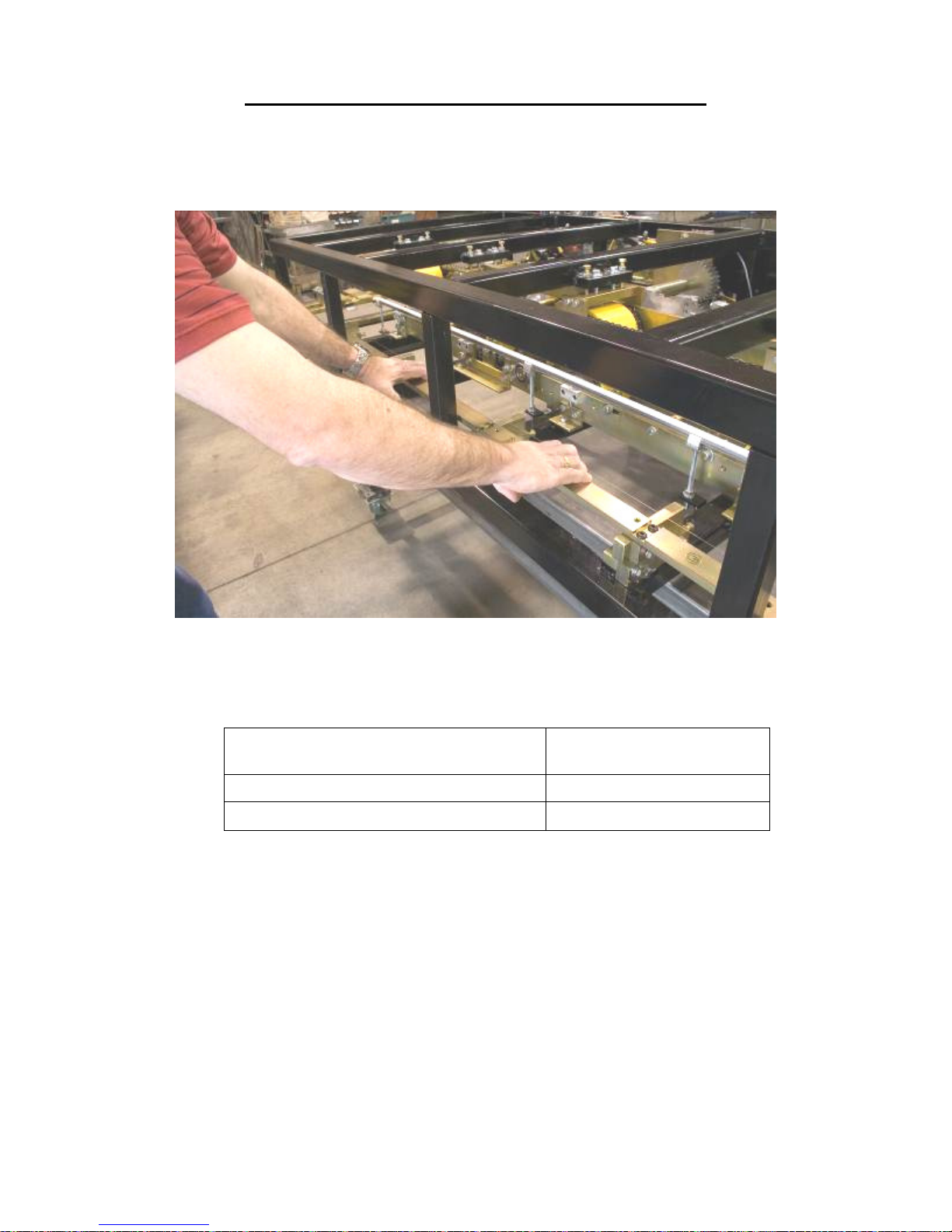
5. Once all 4 bolts are loose, slide the Right Side Fixed Mount Rail #1 to the correct
position (Figure 43), either “inboard” or “outboard". Make sure that it is fully in
position and then tighten the “C” bolts (Figure 41 or Figure 42).
Figure 43: Right Side Fixed Mount Rail
6. Locate your profile in the chart below to see what position the Left Side Fixed
Mount Rail #1 needs to be in.
PROFILE
SS200/210A, SS550, SS675 POSITION "A", OUTBOARD
SS100, SS150, SS450, FF100, FF150, BP POSITION "B", INBOARD
Figure 44: Profile Chart
LEFT SIDE FIXED MOUNT
RAIL #1 POSITION
Now look at the machine to see what position the Left Side Fixed Mount Rail #1
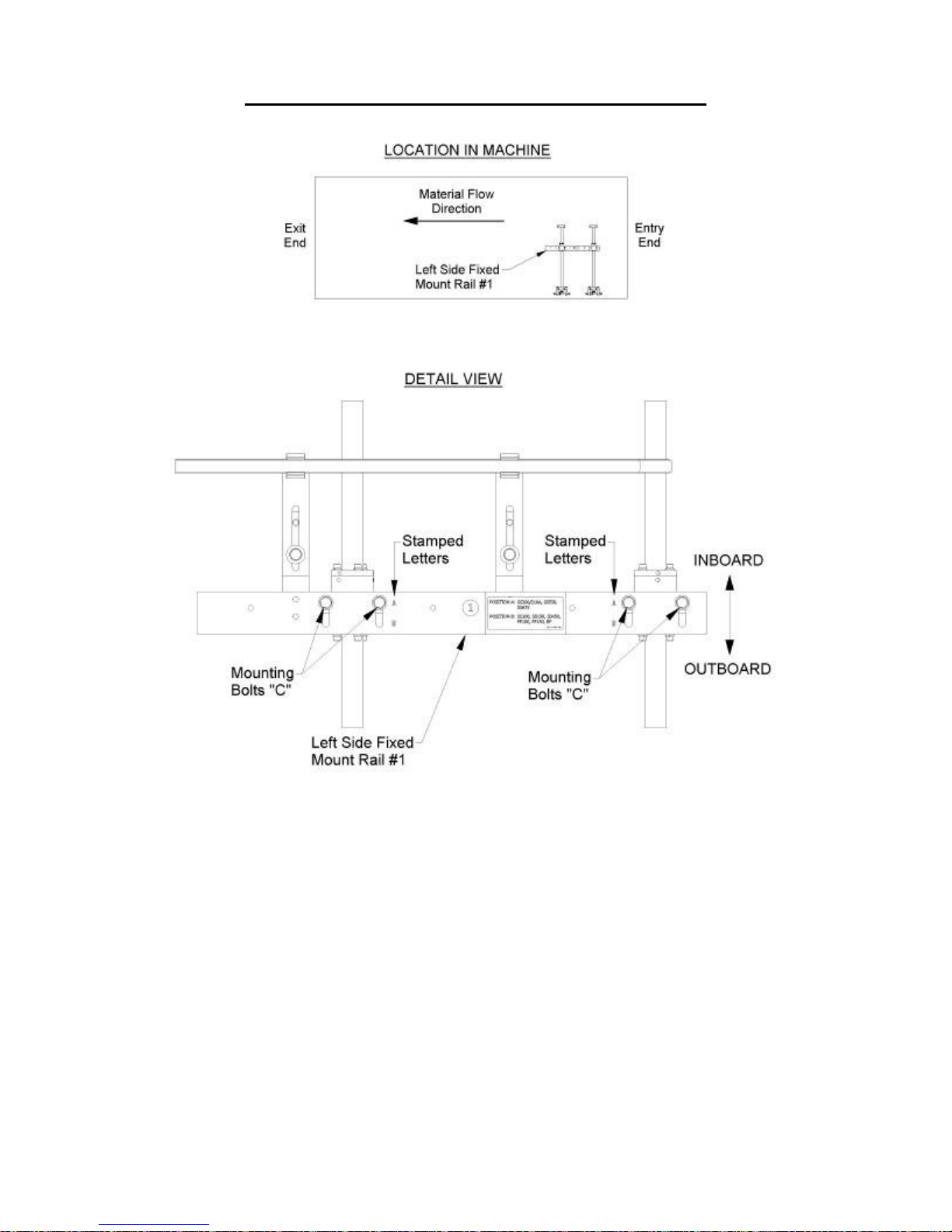
is currently in. The stamped letter closest to the mounting bolts "C" indicates the
position (Figure 46). If it is in the correct position proceed to Step 7, otherwise,
loosen the four mounting bolts "C", slide the Left Side Fixed Mount Rail #1 as far
as it will go in either the "inboard" or "outboard" direction, and re-tighten the
bolts.
53
Page 59
CHAPTER 15
PROFILE CHANGEOVER PROCEDURE
Figure 45: Left Side Fixed Mount Rail
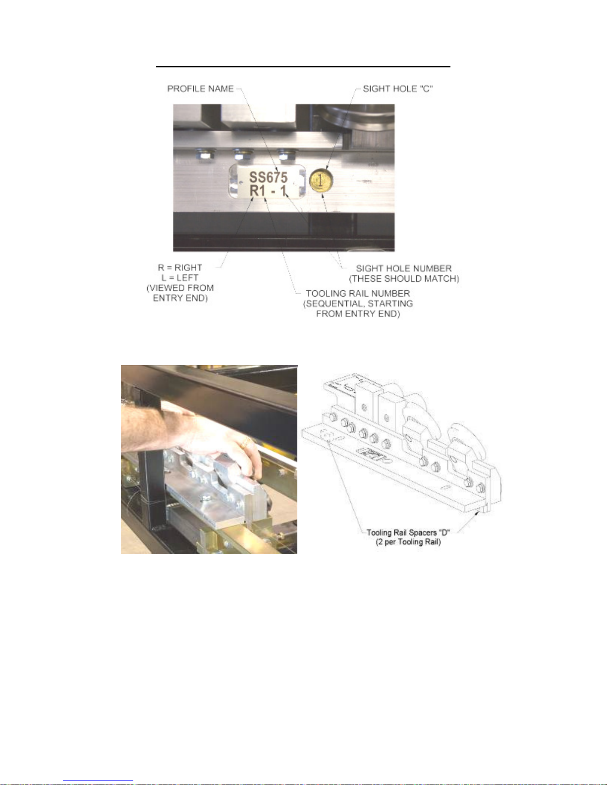
7. Find the R1 Tooling Rail and set it flat on top of the Right Side Fixed Mount Rail
#1 making sure the correct number shows in Sight Hole “C” (Figure 47). Thread
the two mounting bolts into the slots of the rail and finger-tighten them. Pull the
Tooling Rail assembly toward the outside of the machine until the two Tooling
Rail Spacers “D” contact the face of the Fixed Mount Rail. Hold it in place while
tightening the mounting bolts with a ½” wrench.
Figure 46: Shown in the “A” position
54
Page 60
CHAPTER 15
PROFILE CHANGEOVER PROCEDURE
Figure 47: Tooling Rail Identification
Figure 48: R1 Tooling Rail Spacers
8. Continue installing the remainder of the right and left tooling rails in sequence as
described above.
Special Instructions for the SS100, SS150, SS450, and BP Profiles:
The Left #1 Tooling Rail Assembly (L1-1) for these profiles can be mounted
in one of two possible positions based on the required height of the male leg.
When mounting this Tooling Rail Assembly for use with the SS150 or BP
1½" profiles pull it toward the outside of the machine until the two Tooling
Rail Spacers “D” contact the face of the Left Side Fixed Mount Rail #1
55
Page 61
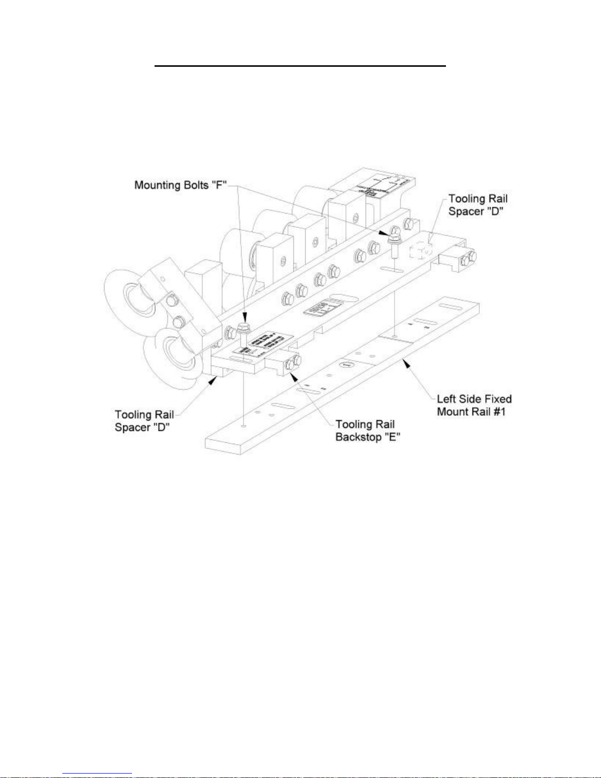
CHAPTER 15
PROFILE CHANGEOVER PROCEDURE
(Figure 49). When mounting the Tooling Rail Assembly for use with the
SS100, SS450, or BP 1" profiles push it toward the center of the machine
until the Tooling Rail Backstops "E" contact the Left Side Fixed Mount Rail
#1 (Figure 49). Once it is positioned properly, tighten the two Mounting Bolts
"F" using a 1/2" wrench.
Figure 49: L1-1 Special Instructions
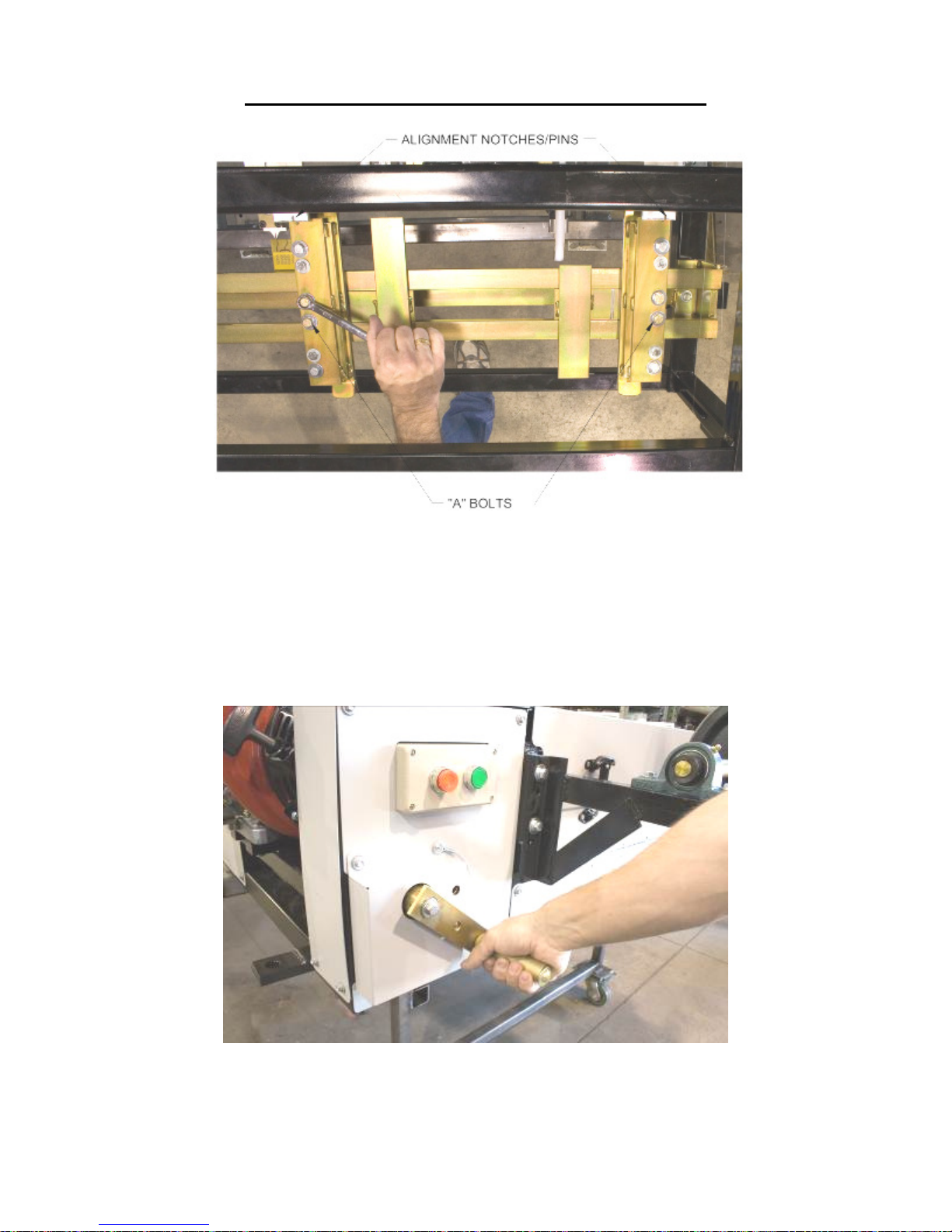
9. Loosen the two “A” Bolts on the Right Entry Guide (Figure 50). Slide the entry
guide to the left or right until the alignment pin, located on the end of the top shoe
of the entry guide, is directly under one of the notches on the Tooling Rail Marker
Plate. Make sure to choose the notch that corresponds to the desired leg
configuration as noted on the decal on the top of the marker plate.
10. Once the Right Entry Guide is in the correct position, tighten the two “A” bolts.
11. Loosen the two “A” bolts on the Left Entry Guide (Figure 50).
12. Slide the entry guide to the left or right to accept the new coil width. Make sure
that the coil is captured snugly between the entry guides and re-tighten the two
“A” bolts.
56
Page 62
CHAPTER 15
PROFILE CHANGEOVER PROCEDURE
Figure 50: Entry Guide Alignment Notches and Pins
13. Using the Tooling Rail Adjustment Handle (Figure 51), align the notch on the
tooling rail marker plate to the alignment pin (Figure 25 on page 38) located in
the Left Entry Guide. Make sure to choose the notch that corresponds to the
desired leg configuration as noted on the decal on the marker plate. Turning the
handle clockwise moves the tooling out-ward, turning it counter-clockwise moves
move it in-ward.
Figure 51: Tooling Rail Adjustment Handle
14. Load material onto the Expandable Arbor and align it to the correct position
(Figure 10).
57
Page 63
CHAPTER 15
PROFILE CHANGEOVER PROCEDURE
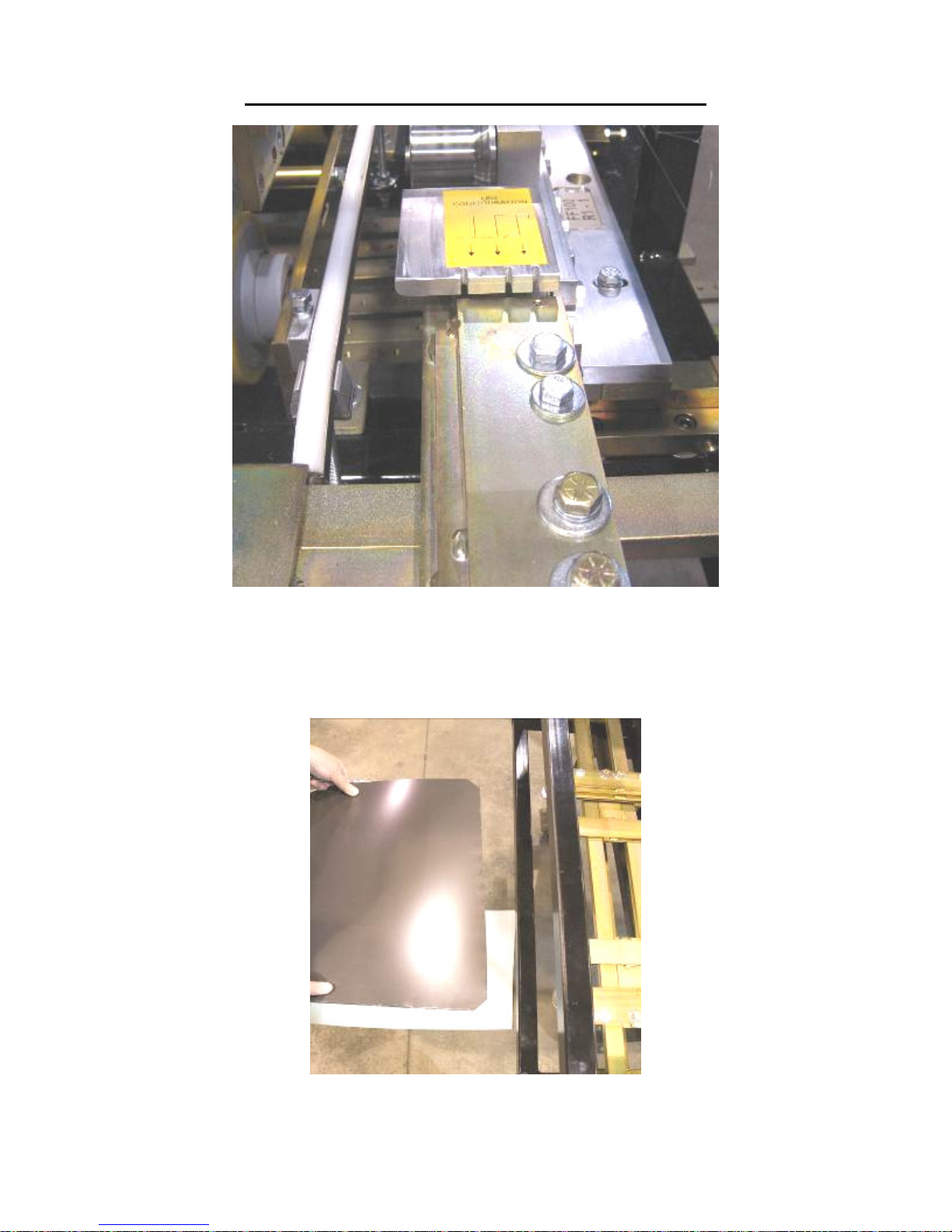
Figure 52: Marker Plate Notch and Pin
15. Load the reeled coil onto the machine using a fork lift or other rated lifting device.
16. Cut a 1” triangle of material off the 2 leading corners of the coil and feed it into
the entry guides.
Figure 53: Preparing Coil for Loading
58
Page 64
CHAPTER 15
PROFILE CHANGEOVER PROCEDURE
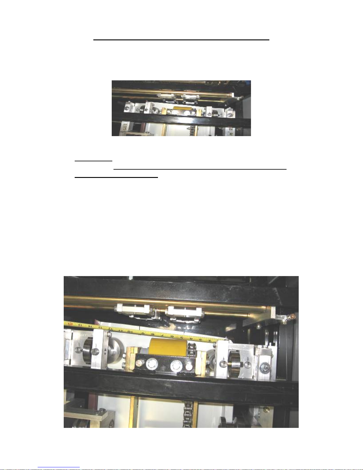
17. Start the machine and use the Jog button on the Manual Control Box or Computer
to jog the material through the machine 6 to 8 inches at a time until it exits the last
forming stations, and is about 1” from the Bead Roller Assembly (Figure 54).
Figure 54: Jogging Material thru Machine
CAUTION: Always make sure your machine is shut down prior to making any
adjustments. DO NOT reach through the opening of the shear while the
machine is running. EVER! To do so could result in serious injury.
IF YOU NEED BEADS IN THE PANEL, GO TO STEP 18
IF YOU DO NOT NEED BEADS IN THE PANEL, GO TO STEP 21.
18. If you require beads in the panel, determine the spacing needed. For Example: a
12” wide panel with 2 beads centered on the panel would give you 3 equal spaces
or 12” divided by 3, which equals 4” from center to center of each bead. Hook the
end of your tape measure on the outside bottom corner of the female leg. Use a
magic marker or grease pencil to mark the 4” and 8” locations on the panel. You
now have 3 equal spaces. (Figure 55)
Figure 55: Spacing Bead Rollers
59
Page 65
CHAPTER 15
PROFILE CHANGEOVER PROCEDURE
19. Loosen the Slide Lock Bolts “D” on the top and bottom bead assemblies
(Figure 21) and slide each bottom and top roll assembly left or right to center
them on the 4” and 8” marks on the panel.
20. Lock the two top bead assemblies in the correct position by tightening the “D”
bolt on each assembly (Figure 21). Next align the bottom bead rollers to the tops
so that the ends of the top and bottom rollers are flush with each other and tighten
the bottom “D” bolts on these 2 assemblies.
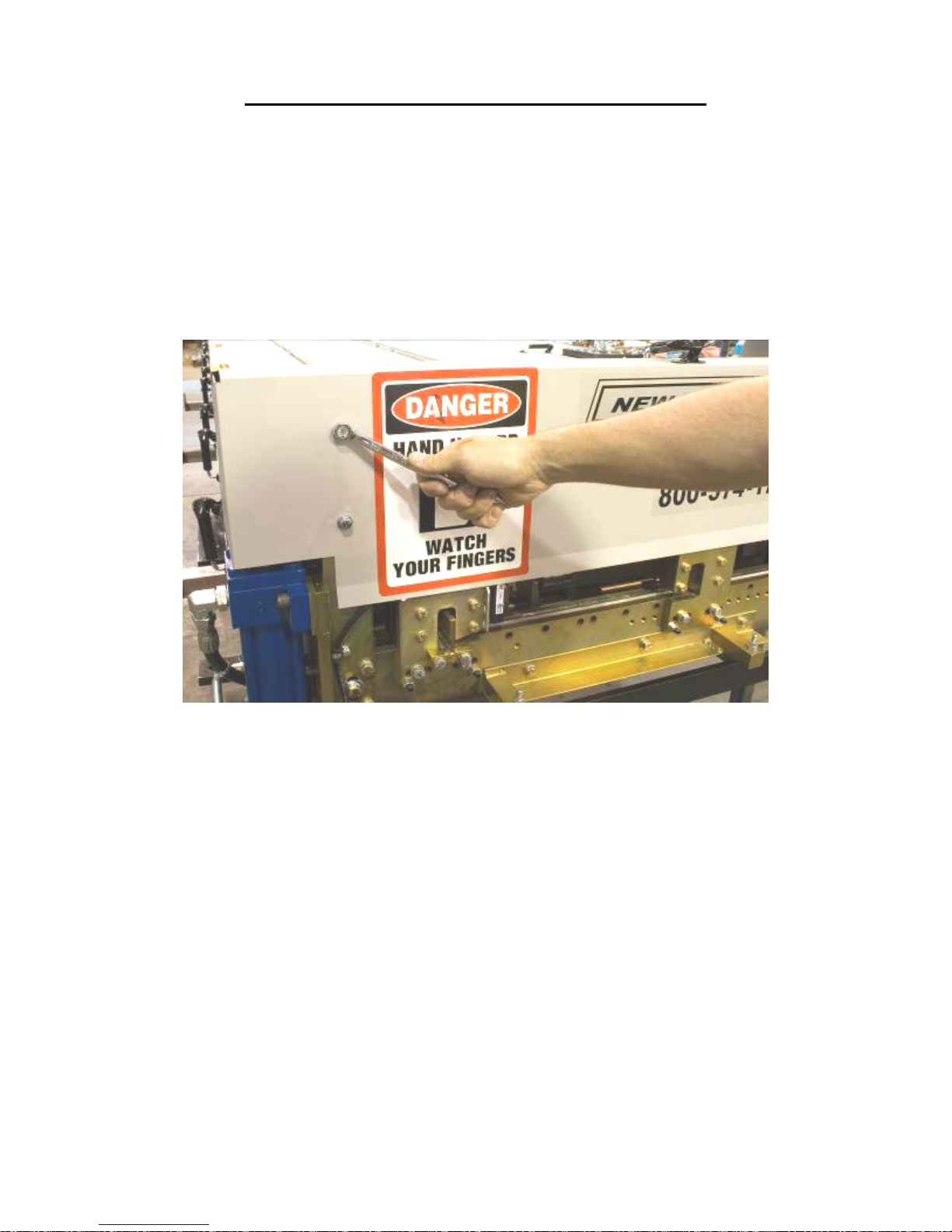
21. Using a 7/16” wrench, remove the Shear Cover and set aside.
Figure 56: Removing Shear Cover
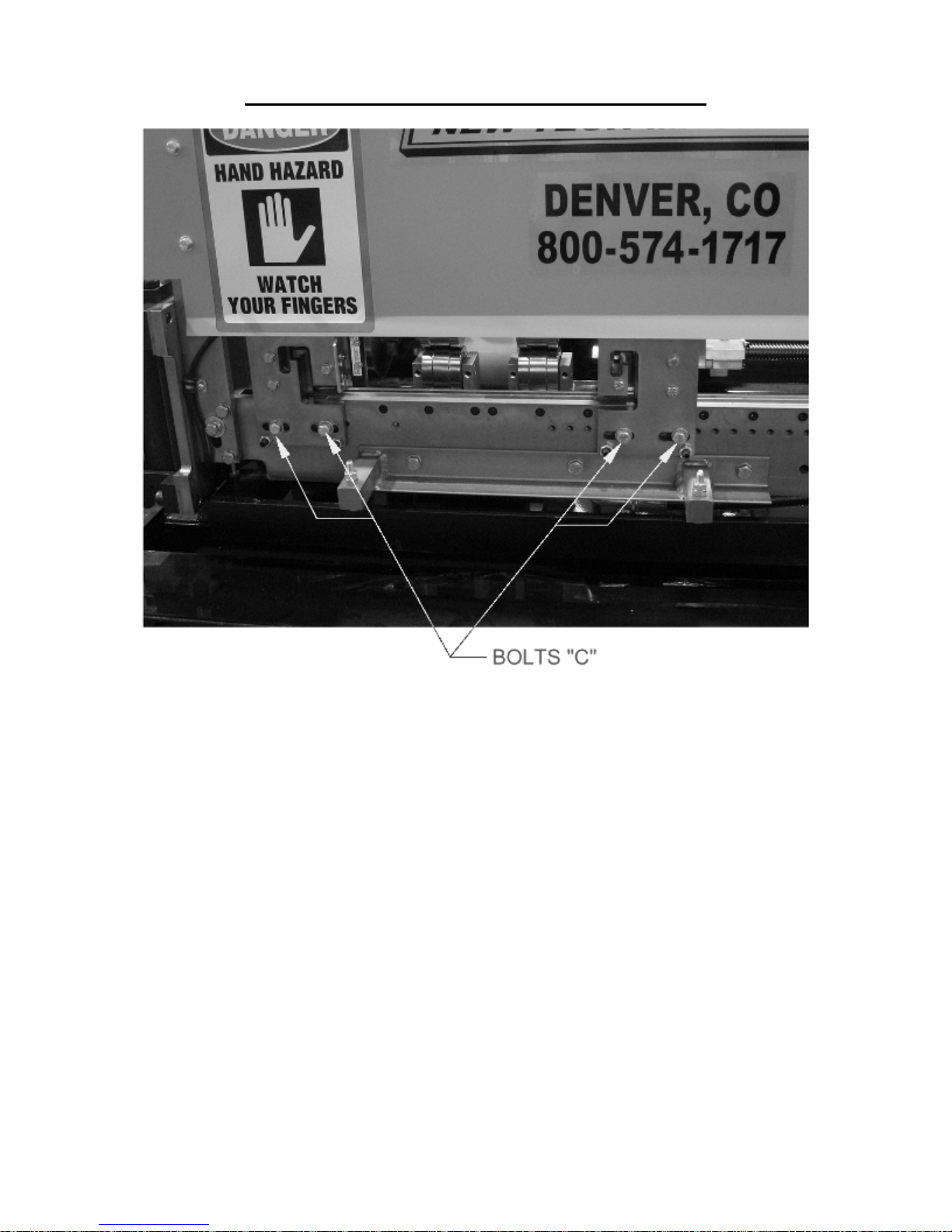
22. Remove the two “C” bolts on the exit male and female shear die assemblies
located in the slotted holes at the bottom edge of the die holder (Figure 57). Store
the shear dies with the profile you just removed, and set the bolts aside for use
when installing the new shear dies.
60
Page 66
CHAPTER 15
PROFILE CHANGEOVER PROCEDURE
Figure 57: Remove Shear Bolts
23. Remove the two “C” bolts from the slotted holes on the entry male and female
shear die assemblies as described previously.
24. Locate the shear dies that correspond to the profile you have just installed.
Separate the male and female entry and exit shear dies.
25. Set the Male Entry Die on top of the Bottom Die (Figure 20 - Detail A on page
32). Visually sight through the male entry die and roughly align it to the forming
tool “line of fire” by sliding it left or right. Re-install the two “C” bolts into the
holes that correspond to the slots. Do not tighten the bolts at this time, just snug
them up.
26. Install the male exit die in the same manner aligning it to the entry die and again,
just snug the bolts.
27. Repeat steps 23 through 26 for the Female Dies.
28. Start the machine and carefully jog the panel up to the shear. Check to see if the
panel will pass through the entry male and female shear dies. If not, FIRST
SHUT THE MACHINE OFF, then move the male and/or female entry dies so
that the panel will pass through them.
Adjust the entry die so that it is as close to the outside vertical portion of the leg
as possible without touching it. Once this is done, tighten the two “C” bolts on
these assemblies.
29. Check the exit male and female shear dies to ensure that the material will pass
through them. If not, adjust as necessary.
61
Page 67
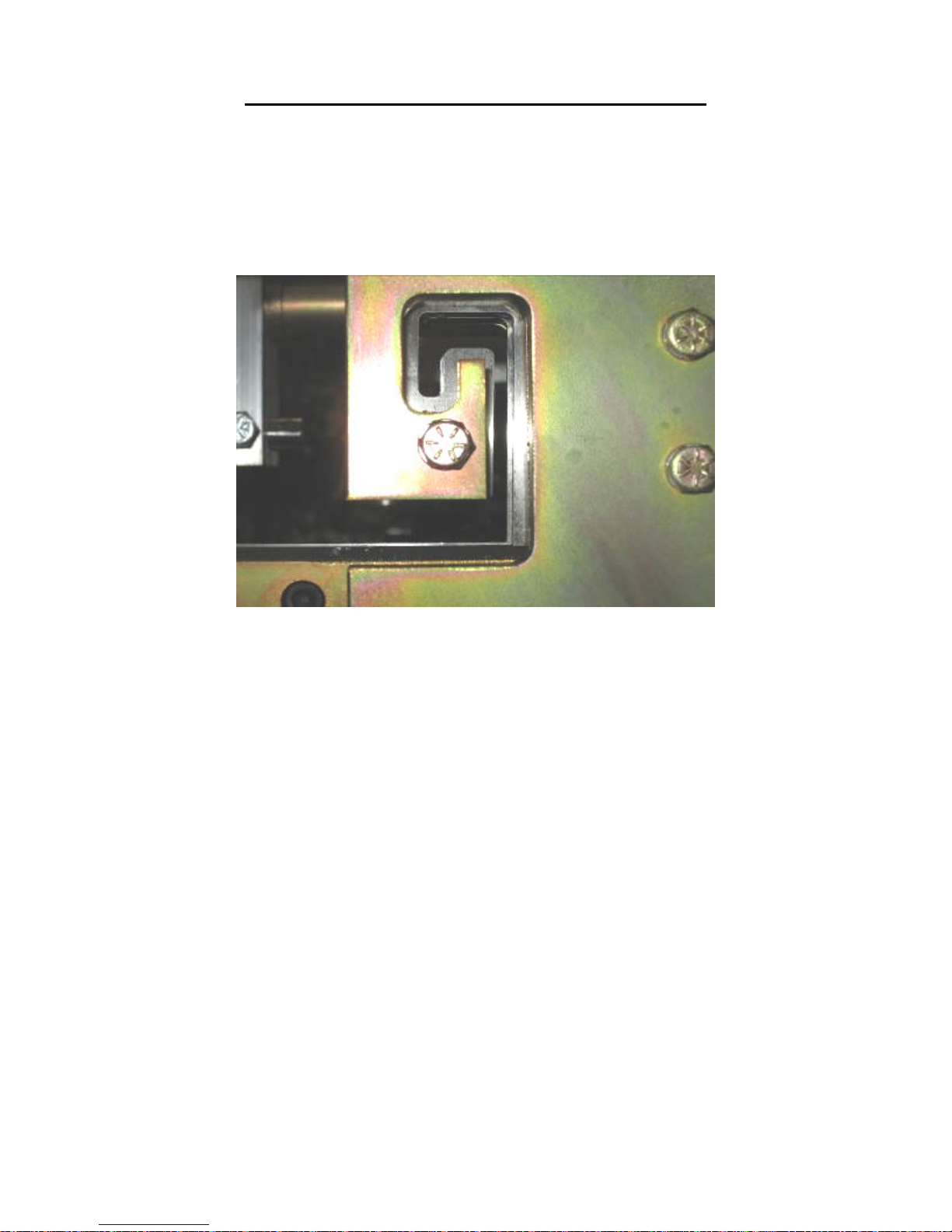
CHAPTER 15
PROFILE CHANGEOVER PROCEDURE
30. Start the machine again and slowly jog the panel approximately 6” past the exit
die and stop. Again, TURN THE MACHINE OFF.
31. Adjust the male and female exit dies so that they are offset to the outside of the
entry die by approximately 1/64” and lock down the two “C” bolts (Figure 58) on
each assembly. This offset is necessary so that after a cut is made, the leading
edge of the panel does not hang up on the exit die.
Figure 58: Exit Die Adjustment
32. Look down the leg of the panel and make sure that the entry and exit dies are not
touching the panel as it passes through them.
33. Start the machine and press the shear down button to cut off the panel, then jog
the material through the shear approximately 2” and stop.
34. Inspect the two cuts and adjust the dies as necessary until an acceptable cut is
achieved. Again, TURN THE MACHINE OFF BEFORE MAKING ANY
ADJUSTMENTS! NEVER REACH THROUGH THE SHEAR WHILE
THE MACHINE IS RUNNING. SERIOUS INJURY COULD RESULT!
35. Once the cut is acceptable, you are ready to start panel production.
62
Page 68
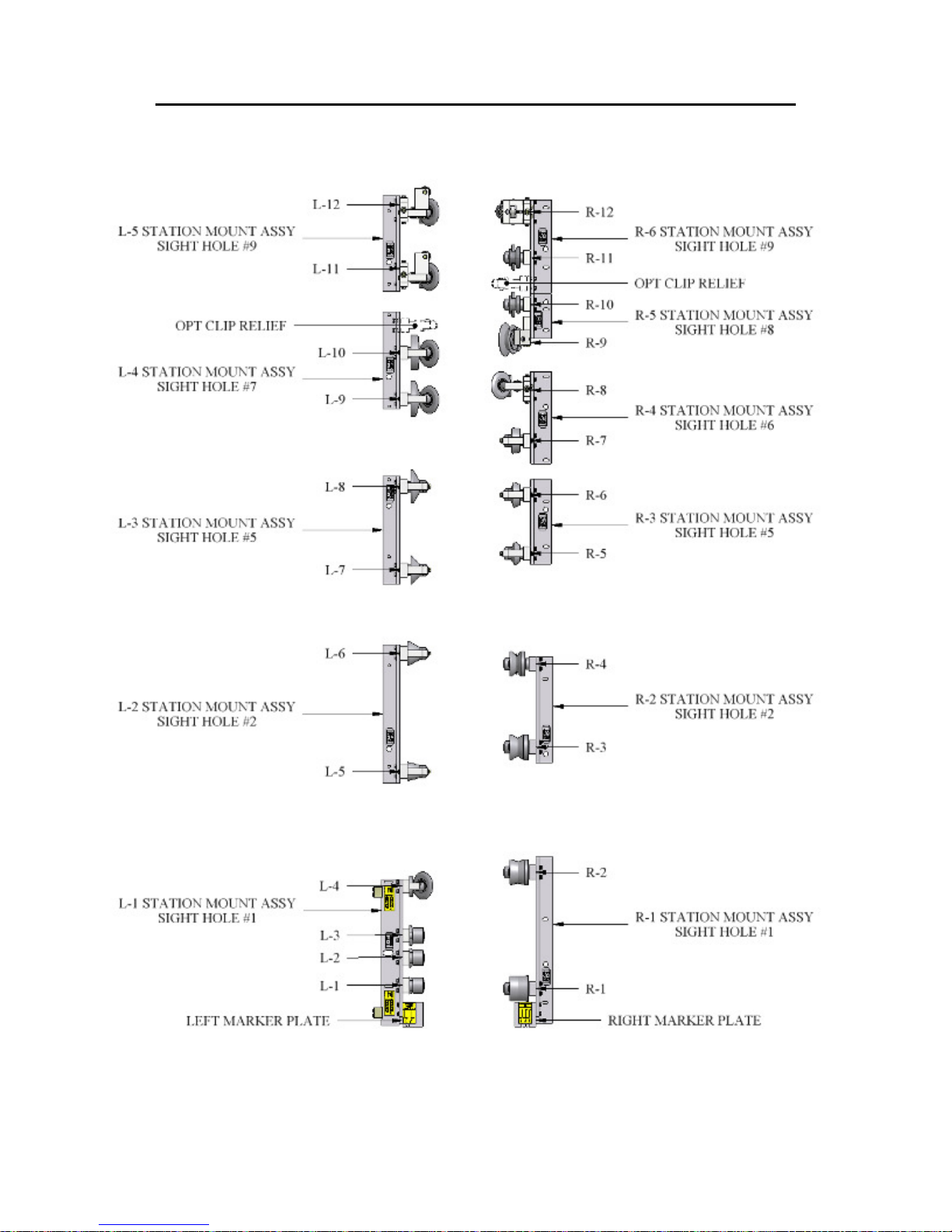
CHAPTER 16
ROLLER SYSTEMS AND PANEL PROFILE DRAWINGS
ROLLER SYSTEMS AND PANEL PROFILE DRAWINGS
Figure 59: SSQ100 Roller System
63
Page 69
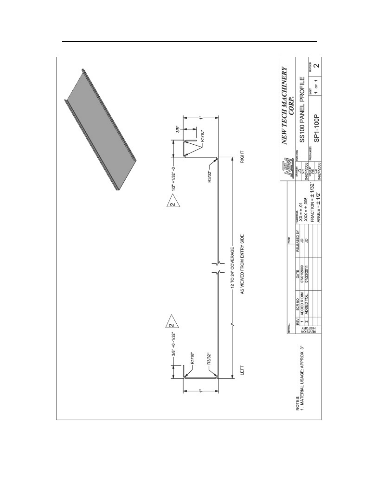
CHAPTER 16
ROLLER SYSTEMS AND PANEL PROFILE DRAWINGS
Figure 60: SS100 Panel Profile
64
Page 70
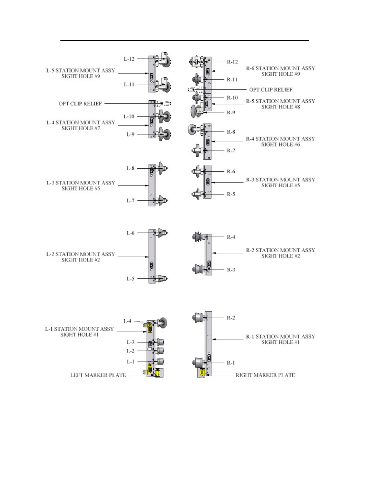
CHAPTER 16
ROLLER SYSTEMS AND PANEL PROFILE DRAWINGS
Figure 61: SSQ150 Roller System
65
Page 71
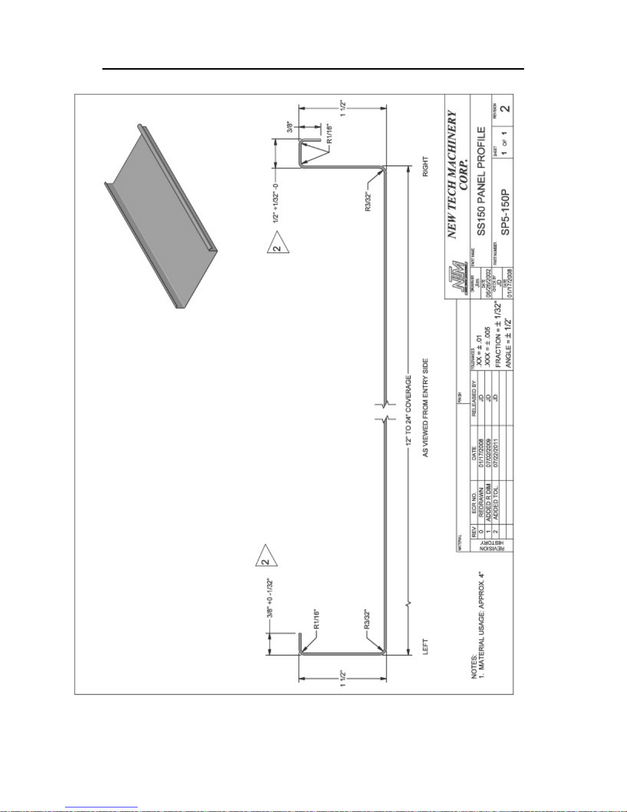
CHAPTER 16
ROLLER SYSTEMS AND PANEL PROFILE DRAWINGS
Figure 62: SS150 Panel Profile
66
Page 72
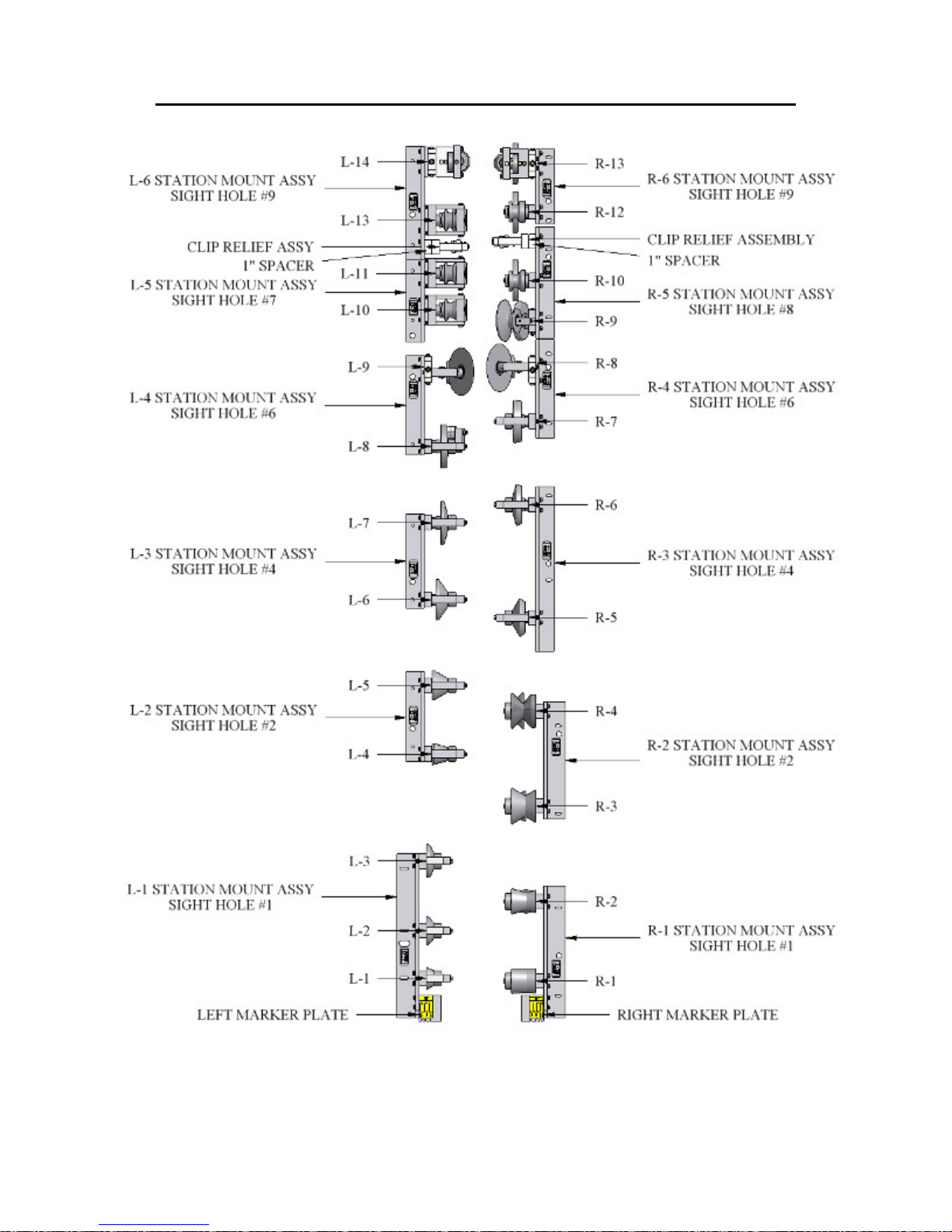
CHAPTER 16
ROLLER SYSTEMS AND PANEL PROFILE DRAWINGS
Figure 63: SSQ200/210A Roller System
67
Page 73
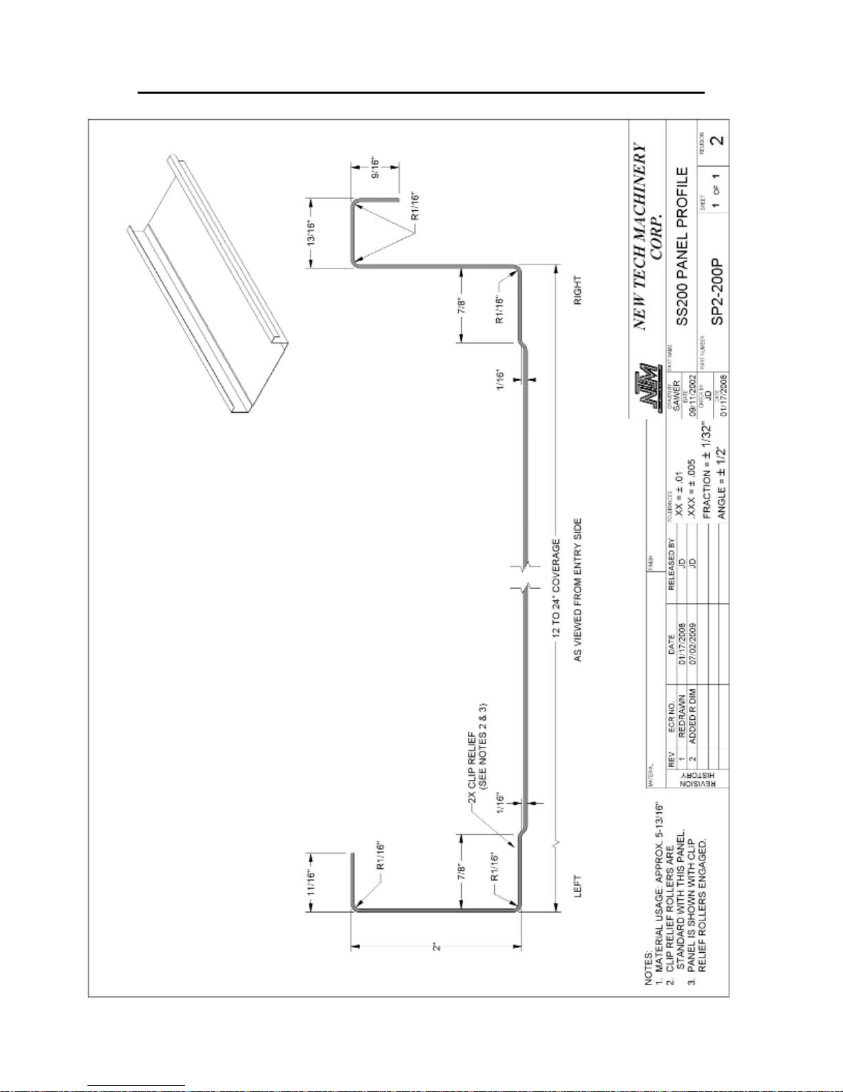
CHAPTER 16
ROLLER SYSTEMS AND PANEL PROFILE DRAWINGS
Figure 64: SS200 Panel Profile
68
Page 74
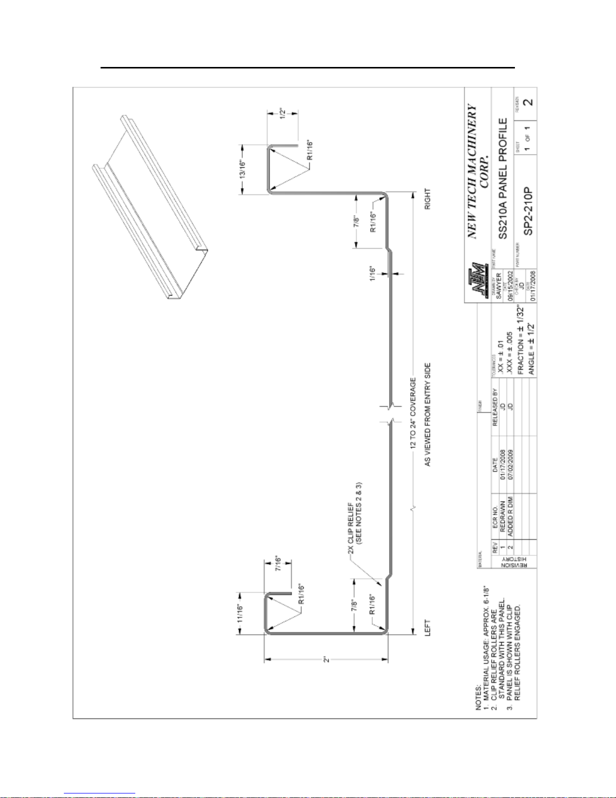
CHAPTER 16
ROLLER SYSTEMS AND PANEL PROFILE DRAWINGS
Figure 65: SS210 Panel Profile
69
Page 75
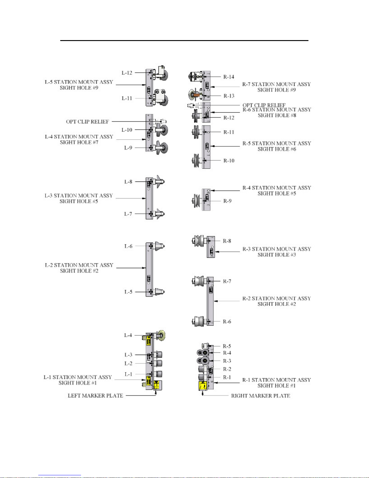
CHAPTER 16
ROLLER SYSTEMS AND PANEL PROFILE DRAWINGS
Figure 66: SSQ450/450SL Roller System
70
Page 76
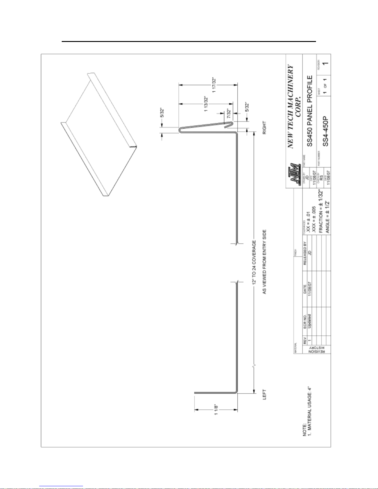
CHAPTER 16
ROLLER SYSTEMS AND PANEL PROFILE DRAWINGS
Figure 67: SS450 Panel Profile
71
Page 77
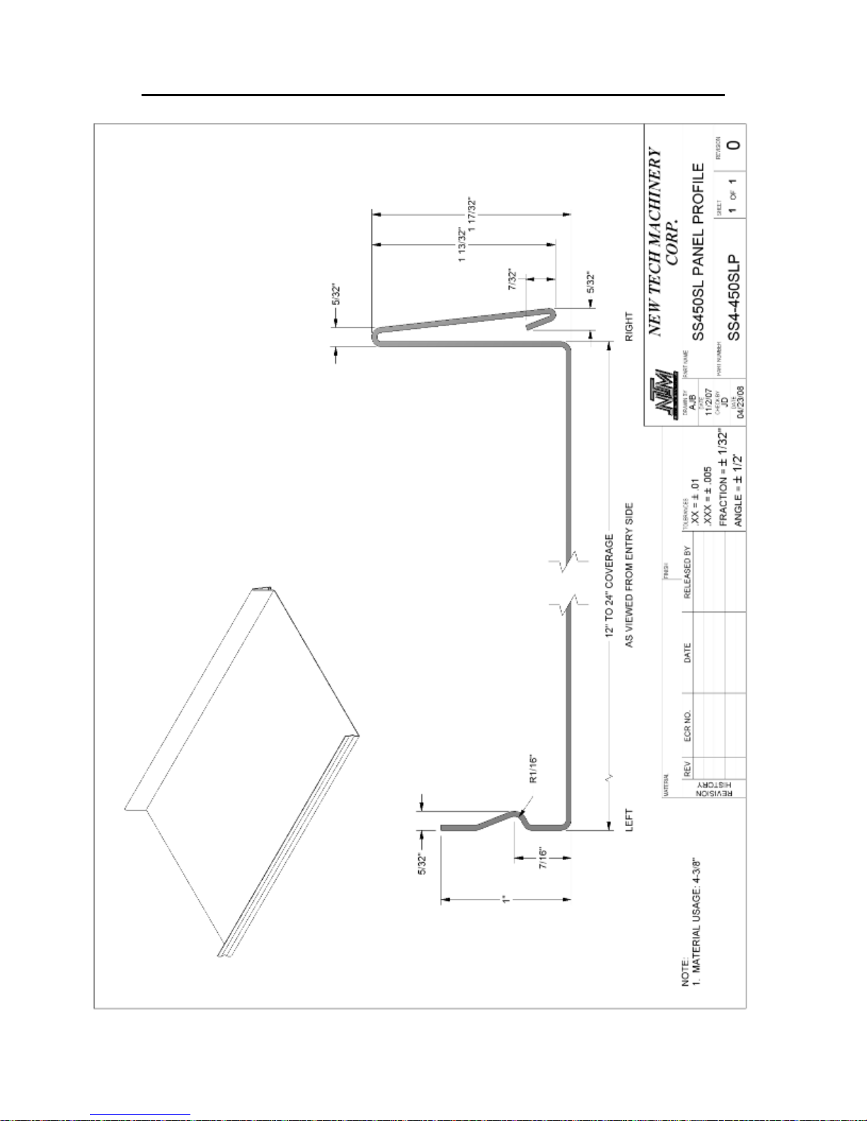
CHAPTER 16
ROLLER SYSTEMS AND PANEL PROFILE DRAWINGS
Figure 68: SS450SL Panel Profile
72
Page 78
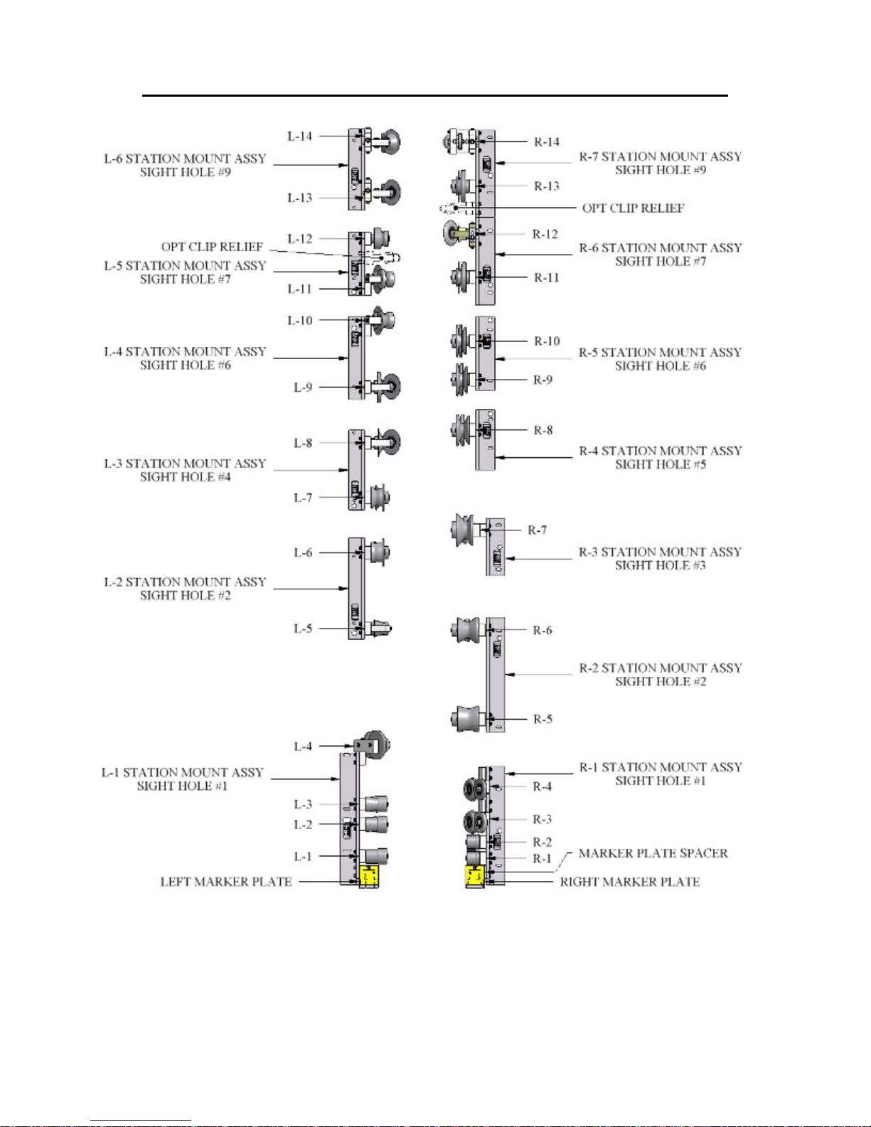
CHAPTER 16
ROLLER SYSTEMS AND PANEL PROFILE DRAWINGS
Figure 69: SSQ550 Roller System
73
Page 79
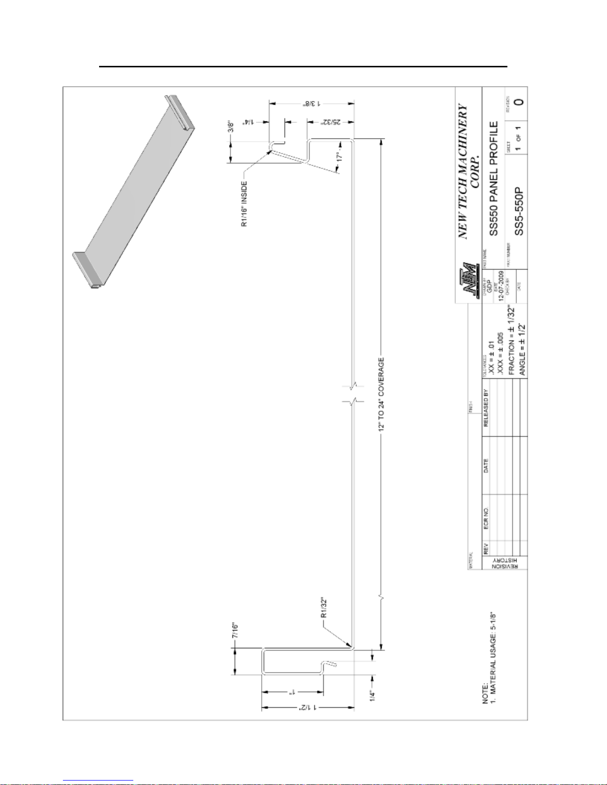
CHAPTER 16
ROLLER SYSTEMS AND PANEL PROFILE DRAWINGS
Figure 70: SS550 Panel Profile
74
Page 80
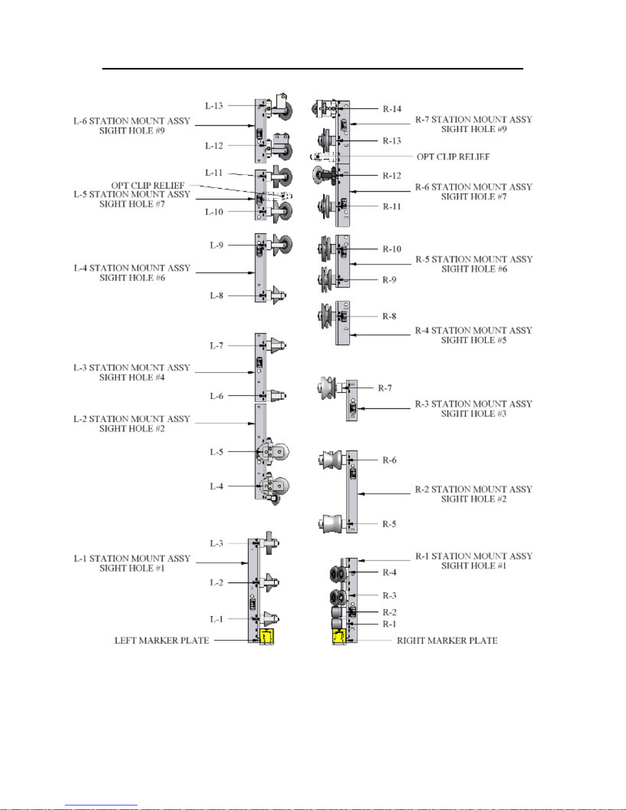
CHAPTER 16
ROLLER SYSTEMS AND PANEL PROFILE DRAWINGS
Figure 71: SSQ675 Roller System
75
Page 81
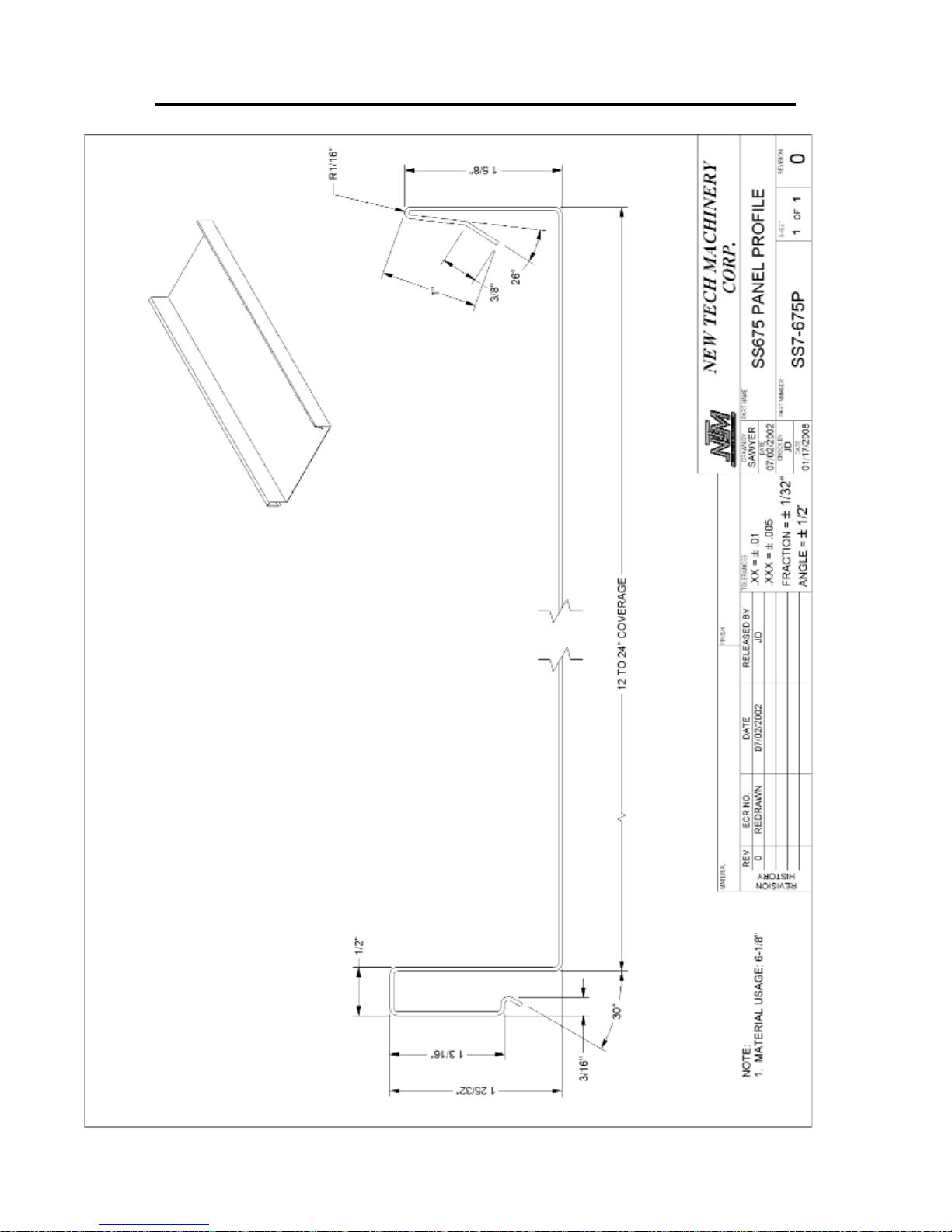
CHAPTER 16
ROLLER SYSTEMS AND PANEL PROFILE DRAWINGS
Figure 72: SS675 Panel Profile
76
Page 82
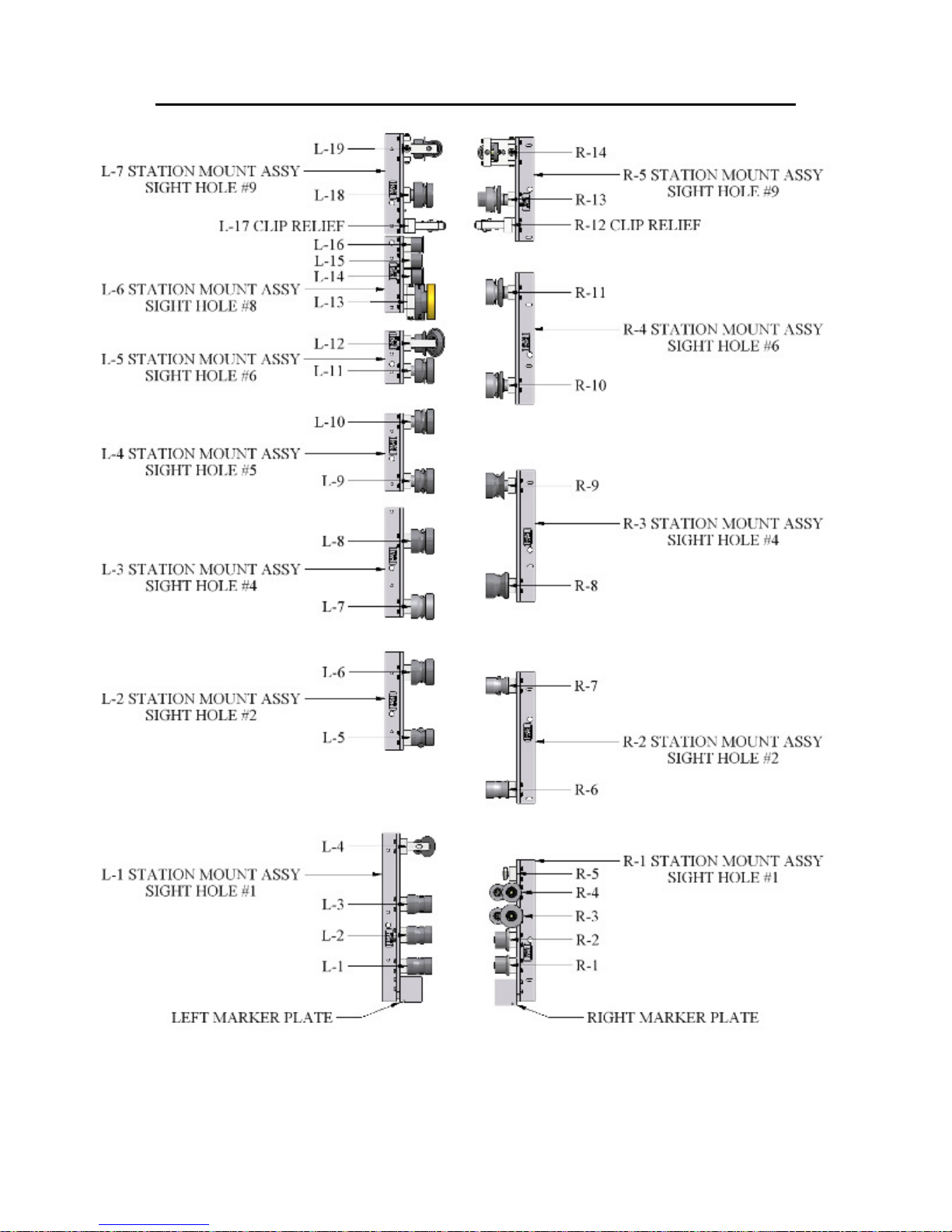
CHAPTER 16
ROLLER SYSTEMS AND PANEL PROFILE DRAWINGS
Figure 73: FFQ100 Roller System
77
Page 83
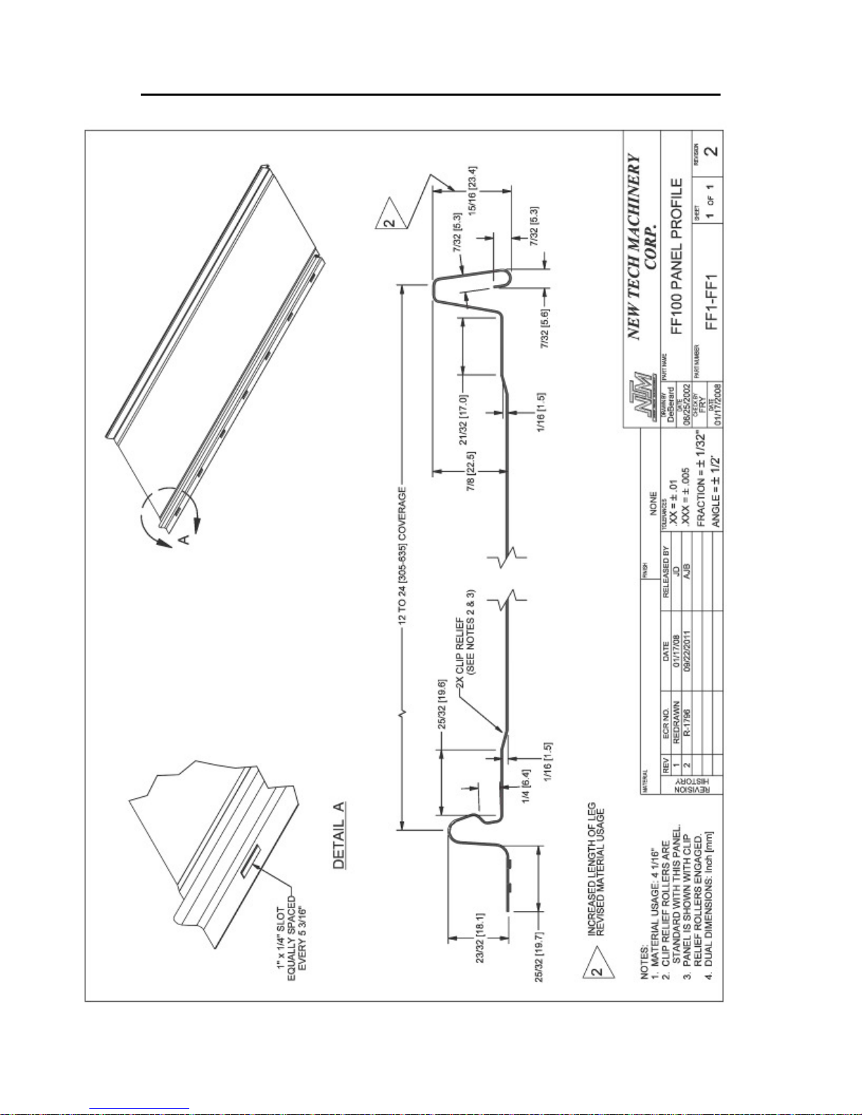
CHAPTER 16
ROLLER SYSTEMS AND PANEL PROFILE DRAWINGS
Figure 74: FF100 Panel
78
Page 84
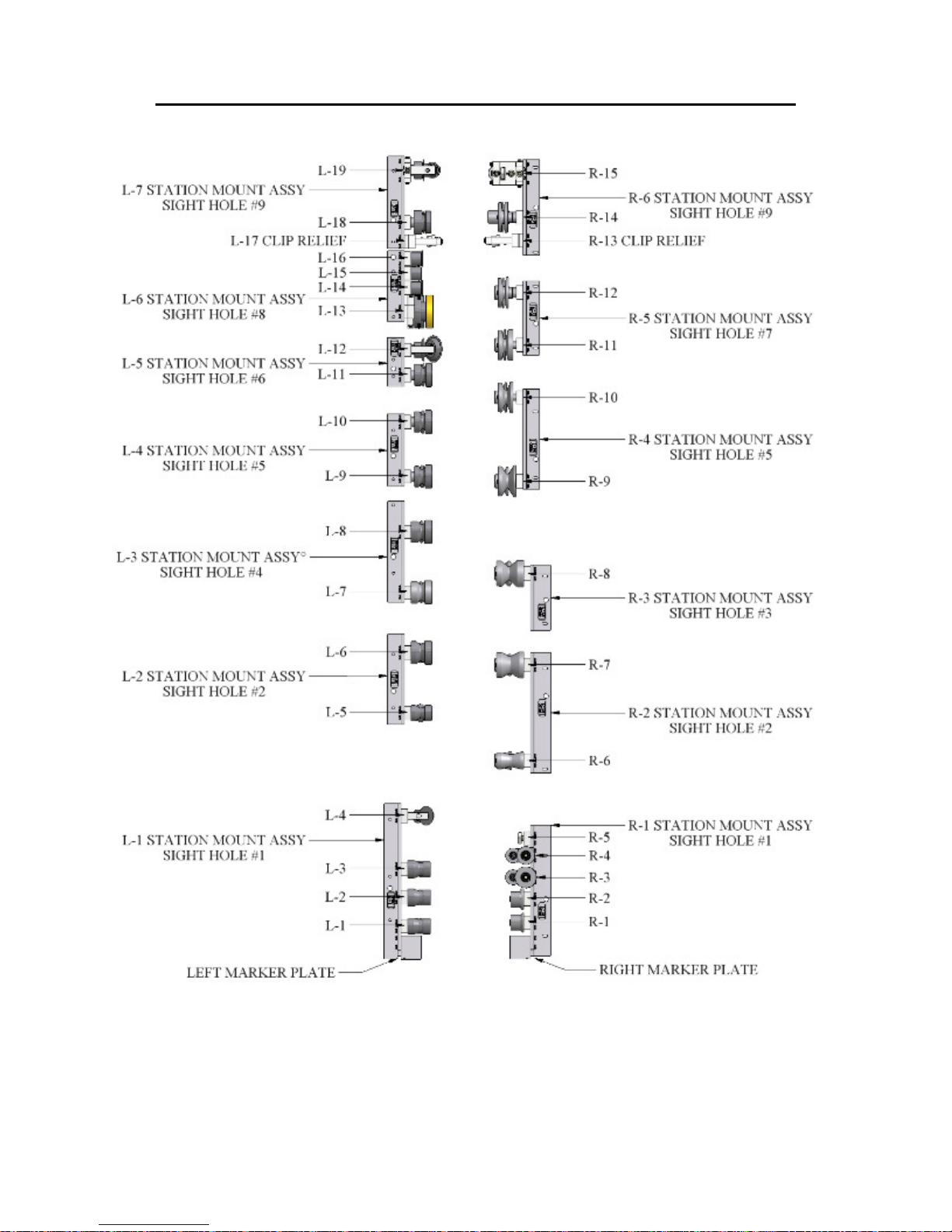
CHAPTER 16
ROLLER SYSTEMS AND PANEL PROFILE DRAWINGS
Figure 75: FFQ150 Roller System
79
Page 85
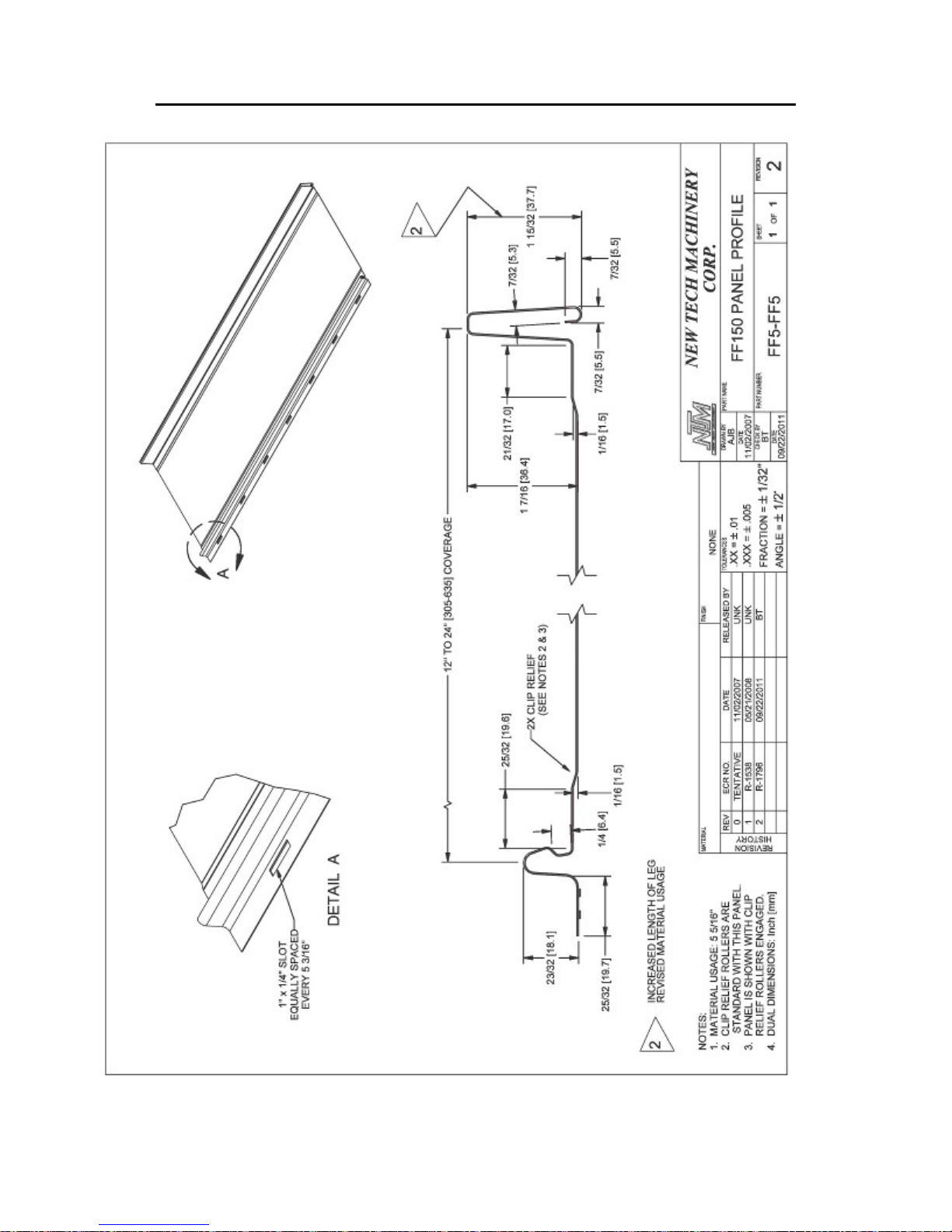
CHAPTER 16
ROLLER SYSTEMS AND PANEL PROFILE DRAWINGS
Figure 76: FF150 Panel Profile
80
Page 86
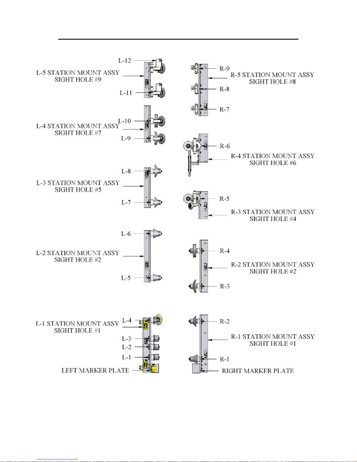
CHAPTER 16
ROLLER SYSTEMS AND PANEL PROFILE DRAWINGS
Figure 77: SSQBP Roller System
81
Page 87
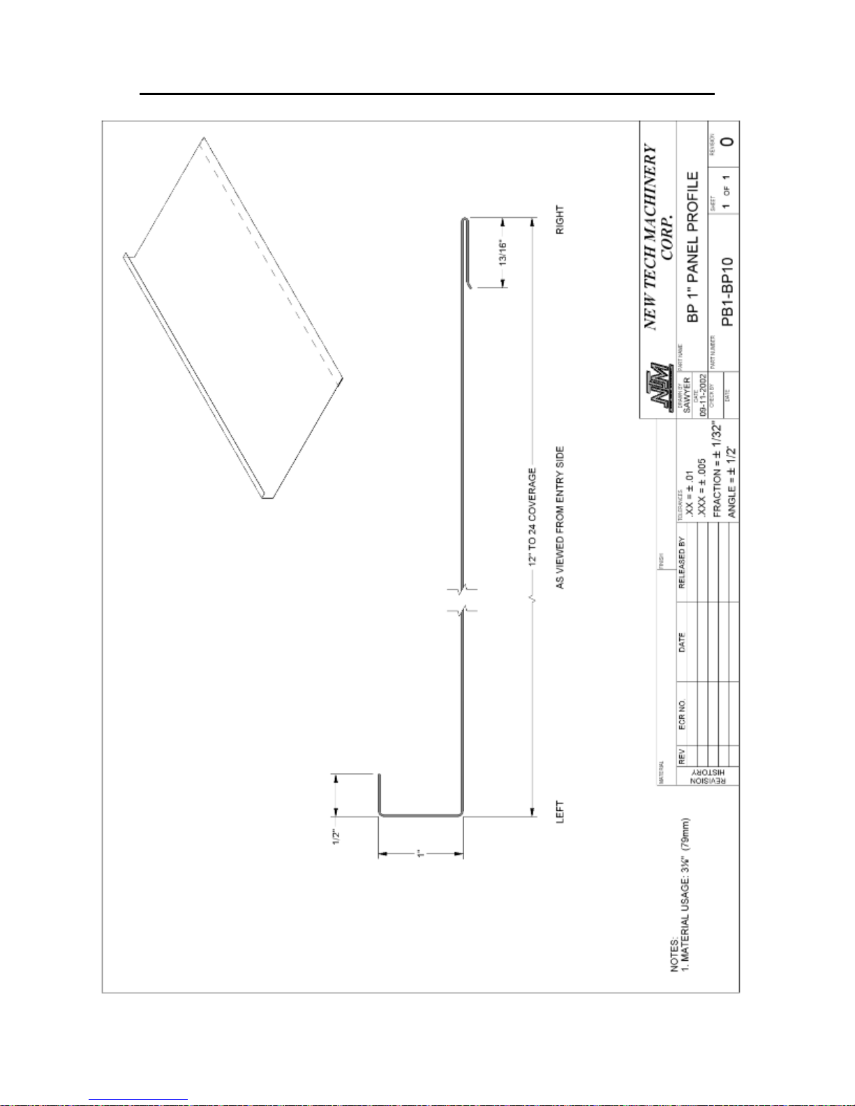
CHAPTER 16
ROLLER SYSTEMS AND PANEL PROFILE DRAWINGS
Figure 78: BP 1” Panel
82
Page 88
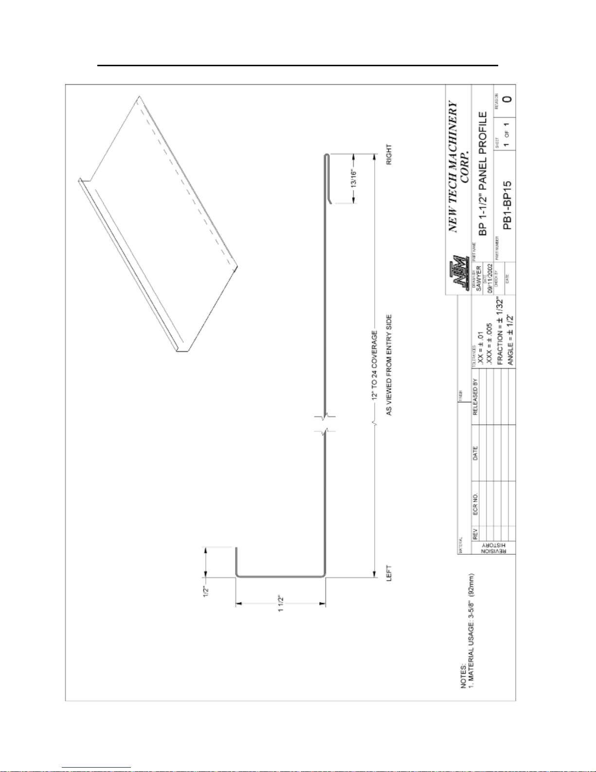
CHAPTER 16
ROLLER SYSTEMS AND PANEL PROFILE DRAWINGS
Figure 79: BP 1 1/2” Panel
83
Page 89

CHAPTER 17
RUN OUT TABLES AND REMOTE LIMIT SWITCH
RUN OUT TABLES AND REMOTE LIMIT SWITCH
The Run-Out Table (Figure 80 & Figure 81) attaches to the Exit End of the Shear
assembly, and is used to support the panel as it exits the machine. It is available in 10 ft.
long sections that fasten together, and have adjustable legs so they can be set to the
correct height. The Remote Limit Switch (Figure 7 on page 14) is designed to be used
with the run out tables for controlling panel length.
1. Set the first Run-Out Table on its side and in front of the machine with the leg
assembly away from the shear.
2. Open the leg assembly and set it upright on the ground.
3. Lift the attachment end of the table and drop it over the 2 threaded bolts on the
Shear Run-Out Table Bracket.
4. Loosen the 2 knob-handles on the leg assembly and allow the legs to fall free. Sight
the height of the table on the left and right side adjusting it level to the machine
using the knob-handles to lock the legs in place. See Figure 81 for correct and
incorrect set up and details.
5. Repeat the above procedures for each succeeding table and attach it to the bracket
on the end of the previous table.
84
Page 90
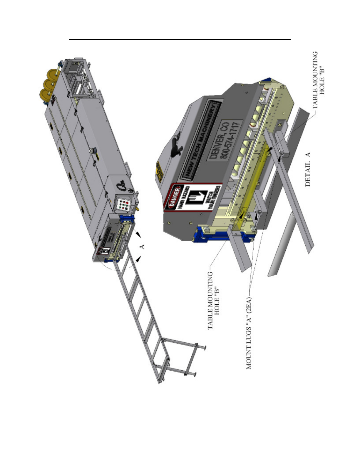
CHAPTER 17
RUN OUT TABLES AND REMOTE LIMIT SWITCH
Figure 80: Run Out Table
85
Page 91
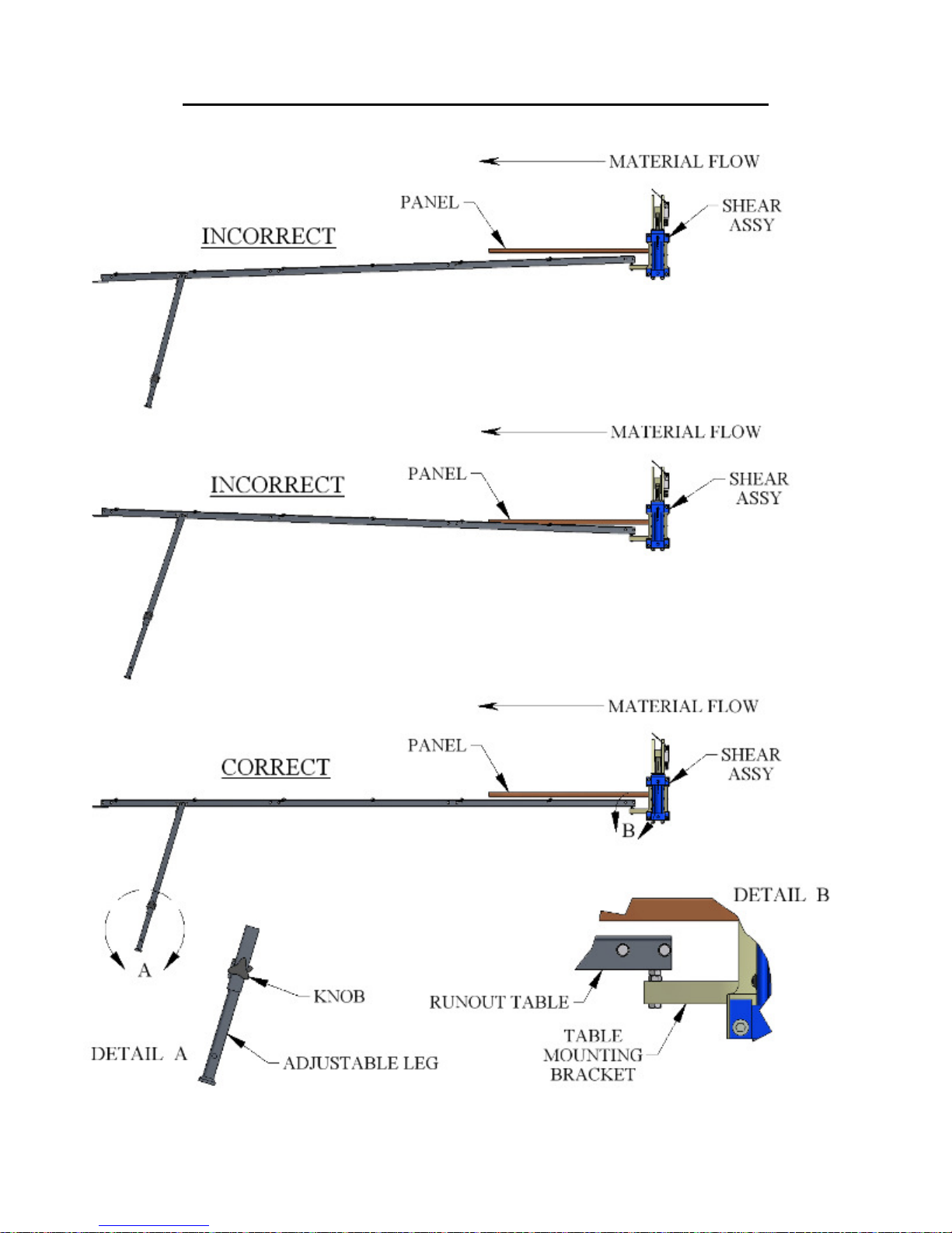
CHAPTER 17
RUN OUT TABLES AND REMOTE LIMIT SWITCH
Figure 81: Run Out Table Setup
86
Page 92

CHAPTER 18
QUICK CHANGE POWER PAC
QUICK CHANGE POWER PAC
The Quick Change Power Pac for your machine allows you to change from one power
source to another very quickly. For example, it is useful for people who need to run their
machine at the jobsite with a gas engine and use it in a factory or indoor setting as well. It
requires two people to lift the Power Pac out of and into the machine. To change the
power pac see below.
Refer to Figure 82
POWER PAC REMOVAL
1. Remove the screws holding the #1 Left Cover on the machine. Set cover aside.
2. Using a 9/16” wrench, remove the two “A” bolts and set aside for later use.
3. Separate the Male /Female Connectors of the Main Communication Cable by
unscrewing them from each other.
4. Un-couple the Large and Small Quick Disconnect hydraulic fittings.
5. Using the two handles, have someone help you lift the Quick Change Power Pac
out of the machine and set it aside.
POWER PAC INSTALLATION
1. Using the two handles provided, have someone help you lift the new Power Pac
into position on the machine.
2. Align the two mounting holes under the handles of the Power Pac to the threaded
holes in the frame of the machine. Use the two mounting bolts “A” removed
above to fasten the Power Pac into place and tighten with the 9/16” wrench.
3. Locate the Male and Female Main Communication Cable and fasten them
together. Note that there is a notch in one and a key in the other that must be
aligned for the two to mate together correctly.
4. Connect the Large and Small Quick Disconnect fittings.
87
Page 93
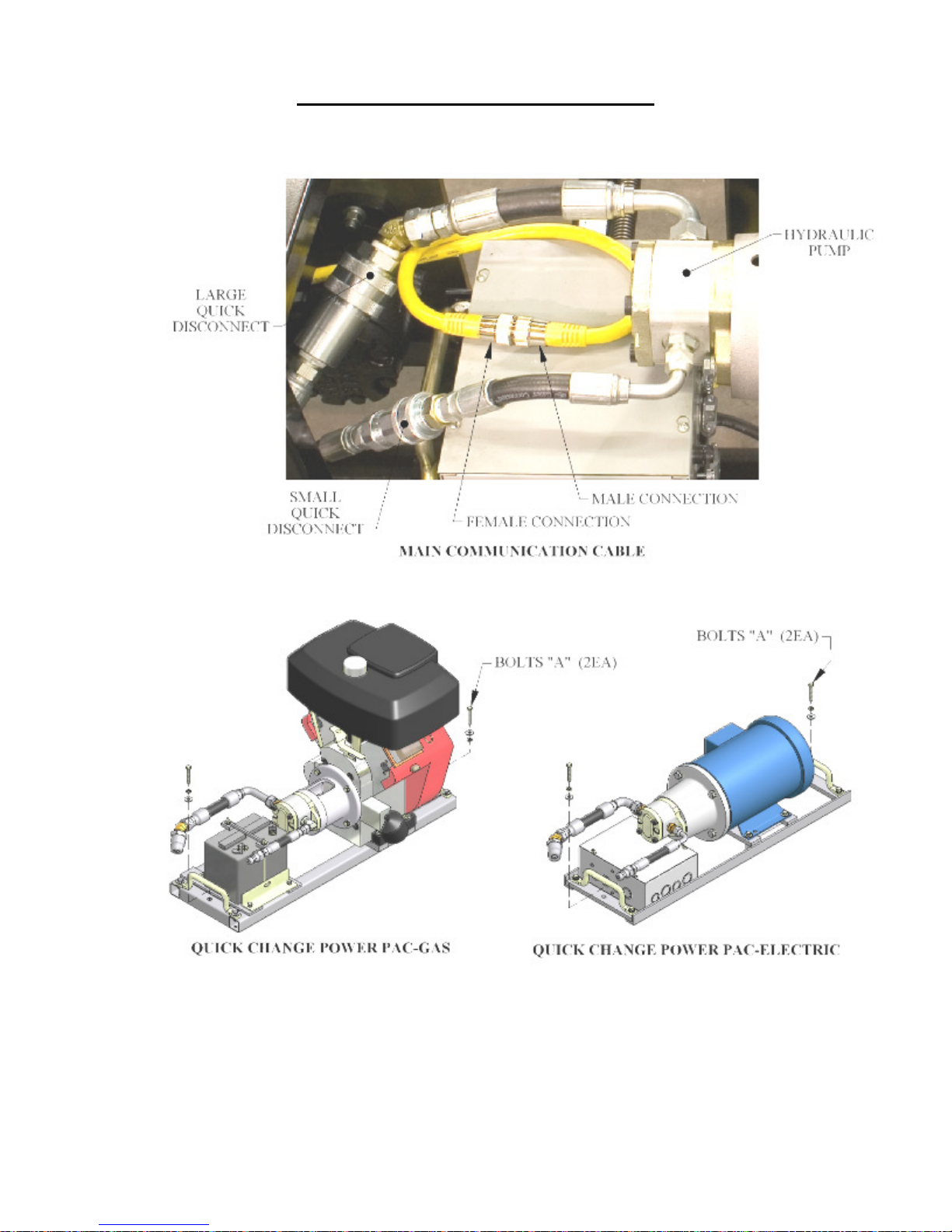
CHAPTER 18
QUICK CHANGE POWER PAC
Figure 82: Cable Connections and Fasteners
88
Page 94
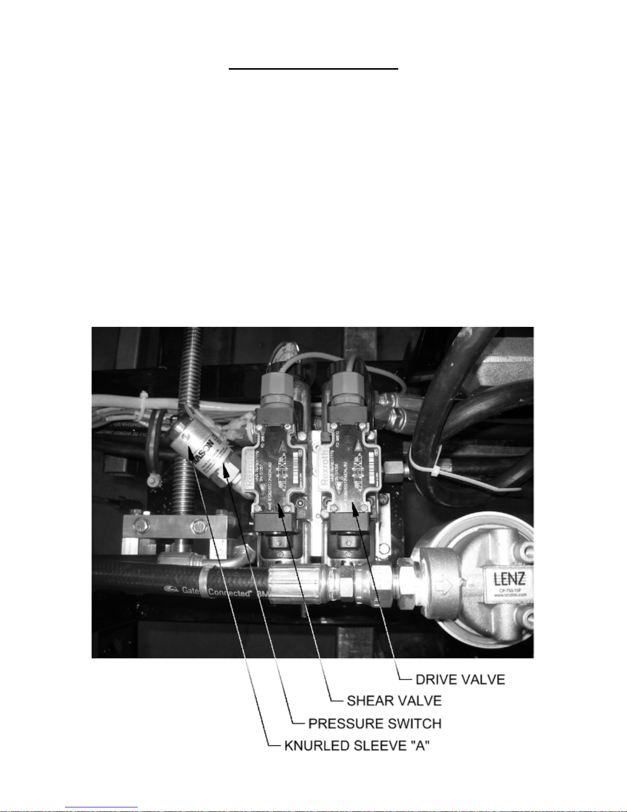
CHAPTER 19
TROUBLESHOOTING
TROUBLESHOOTING
The hydraulic system operates the Shear and Drive assemblies. They are interfaced
together and electronically activated. The hydraulic system pressure is factory set at 2000
psi and should not be changed. Some of the common problems that occur and their
solutions follow below.
1. Shear travels to the bottom of the stroke and does not return to the top of the
stroke. You can hear the hydraulic system laboring and pushing the Red
Shear Up Button does not return it to the top of stroke.
SOLUTION: Adjust the pressure switch (Figure 83) by turning the silver
knurled sleeve “A” counterclockwise until the shear goes up. Note: If you
turn the sleeve to far CCW, you will get problem #2 below on the next cut
made.
Figure 83: Pressure Switch Adjustment
89
Page 95

CHAPTER 19
TROUBLESHOOTING
2. Shear travels to the bottom of the stroke and returns to the top of the stroke
without cutting the panel completely through.
SOLUTION: Press and hold the Green Shear Down Button until the panel is cut
off. Remove the cut panel and jog material out 2 or 3 inches past the shear.
Adjust the pressure switch (Figure 83) by turning the silver knurled sleeve
“A” clockwise 1/8 of a turn. Press the Shear Down Button again. Check to
see if the panel is cut off completely. If not, repeat this procedure until the
cut is made with one stroke of the shear. Note: If you turn the knurled
sleeve too far CW you will experience problem #1 above.
3. Shear is at the top of the stroke, you can hear the hydraulic system laboring
and you cannot run the next panel.
SOLUTION: Remove the Shear Cover. Note the 2 Limit Switch Arms “A”
(Figure 84). Lift the arms one at a time. If one of them stops the hydraulic
system laboring then that Limit Switch arm needs to be adjusted. If neither
of them stops it, lift both arms at the same time to see if it stops. If it does
then both arms need adjusting. ADJUSTMENT: Tape one or both Limit
Switch Arms “A” to the Top Shear Bar “B”. Loosen Hex Nut “C” until
spring tension is released. Using a small flat tipped screwdriver, turn
Slotted Stud “D” toward the entry end of the machine until you hear a
click and stop. Repeat this a few times until you can stop right when the
click occurs. While holding this position, tighten Hex Nut “C” to lock in
adjustment. Adjust one or both sides as required from test above. Start the
engine. If the adjustment/adjustments were done correctly, the hydraulic
system should no longer be laboring and you should be able to run the
next panel.
90
Page 96
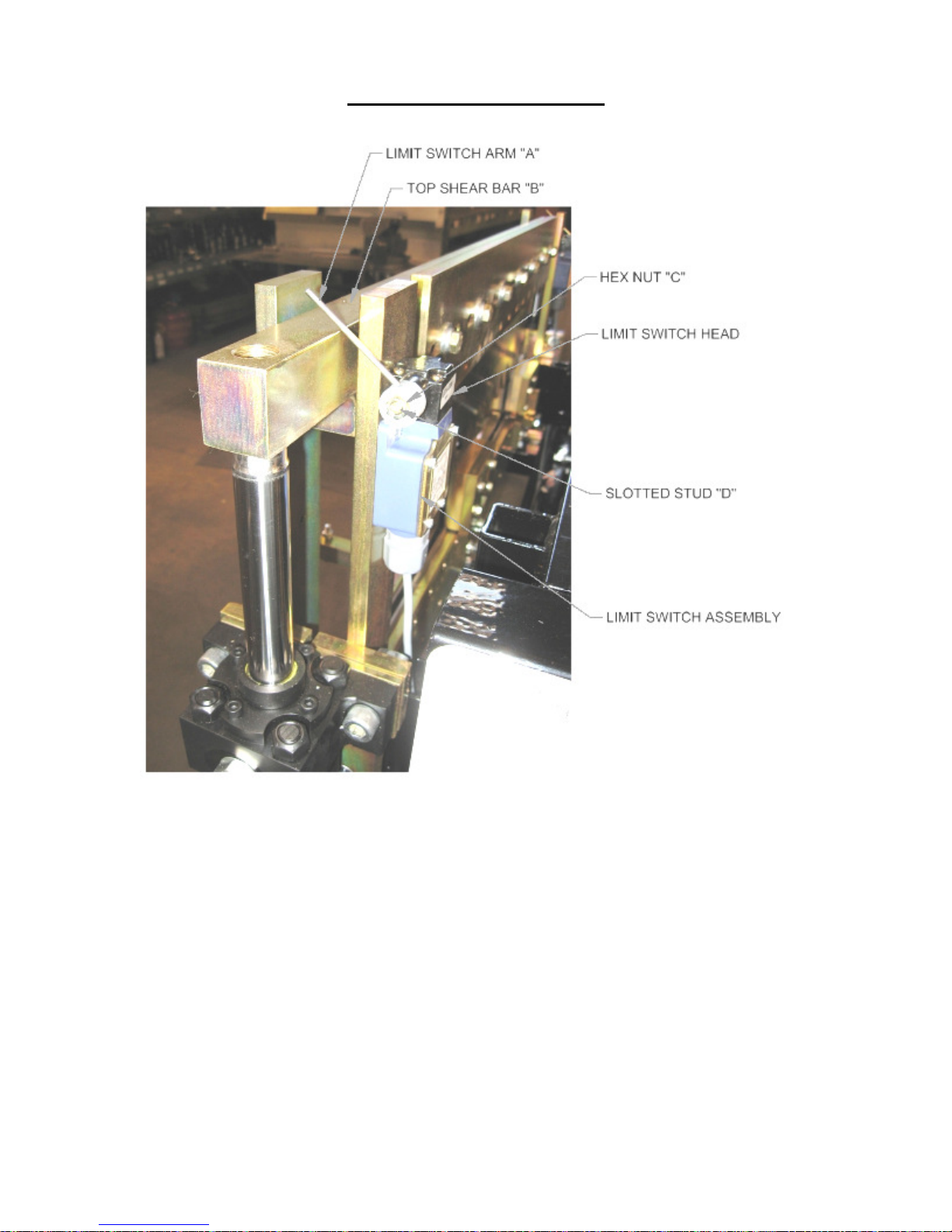
CHAPTER 19
TROUBLESHOOTING
4. After making a cut, the male or female leg of the next panel gets caught on the
exit shear die and damages the panel.
SOLUTION: This problem normally shows up after making a roller system/shear
die change. The entry dies both male and female should be as close to the
vertical leg of the panel as possible without touching. Once this is
achieved, the exit die should be set just outside the vertical leg of the entry
die so that as the fresh cut edge of the panel passes by the exit die it
doesn’t getting caught (Figure 58 on page 62).
5. The male and or female leg gets crushed when shearing.
SOLUTION #1: Check the Shear Blades directly over the male and female legs
to make sure that the points of the blades are in the correct position
(Figure 19 & Figure 20 on page 31).
Figure 84: Limit Switch Adjustment
91
Page 97

CHAPTER 19
TROUBLESHOOTING
SOLUTION #2: Make sure that the shear blades and dies are well lubricated on
both sides with the proper lubricant (See GENERAL MAINENANCE on
page 6).
6. Manual Control Panel buttons do not work.
SOLUTION #1: Check fuse inside of Manual Control Box. Replace if blown with
a 10-amp time delay fuse (Figure 8 on page 15).
SOLUTION #2: If you have a gasoline engine, check the condition of the battery.
The control system requires 12 volts to operate properly. Replace or
charge battery as required.
92
Page 98
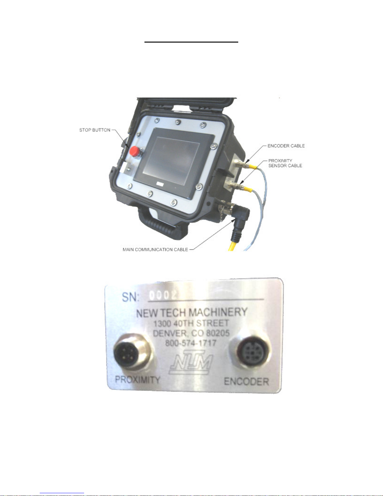
APPENDIX A
PLC CONTROLLER
PLC CONTROLLER
Figure 85: PLC Assembly
Figure 86: Serial Number Plate
A - 1
Page 99
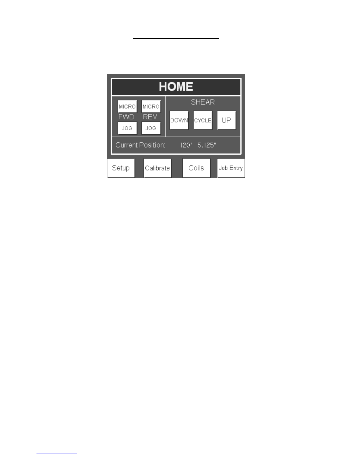
APPENDIX A
PLC CONTROLLER
Home
When the controller is turned on, it will automatically go to the home screen.
Figure 87: Home Screen
Manual Operation
The machine can be manually operated from the home screen by pressing the Jog and
Shear buttons.
JOG:
FWD and REV JOG buttons will jog the machine forward and reverse as long as the
button is depressed. When the JOG buttons are released, the action will stop. The FWD
and REV MICRO buttons will jog the material approximately ¼" each time the button is
pressed.
SHEAR:
The shear UP and DOWN buttons are momentary and will act in a similar manner as the
jog buttons. The SHEAR CYCLE button only needs to be pressed once and the shear
will go to the bottom of the stroke and back up to the top. At any time during the
shearing cycle, the UP button on the display or red stop button next to the screen can be
pressed to return the shear to the top. CAUTION: The shear will stop without returning
to the top if the E-Stop pushbutton on the manual control box below the PLC is pressed.
This button shuts off all power to the machine and machine controls. Upon start-up, the
shear will return to the top.
Automatic Operation
The pre-run sequence must be completed in the correct order before automatic operation
can be utilized.
A - 2
Page 100
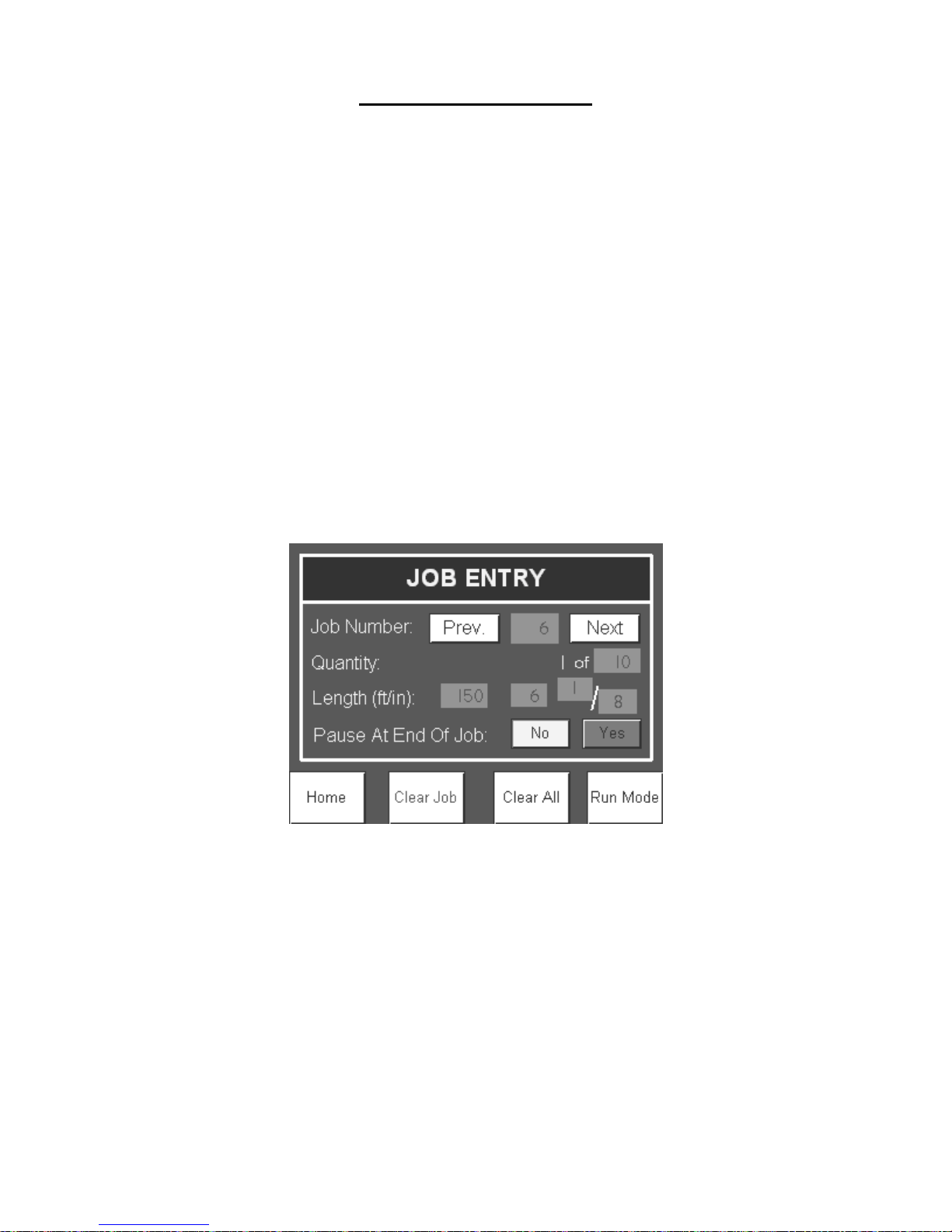
APPENDIX A
PLC CONTROLLER
Pre-Run Sequence:
1. Jog the material forward using the manual FWD JOG or MICRO buttons
on the Home screen or the JOG switch at the entry end of the machine.
The material must exit the shear and be detected by the panel detection
sensor.
2. Shear the material using the Shear Cycle button. At that point, the
machine will be fully loaded with material, the length counter will be reset
and the controller will be ready to run in automatic mode.
If the machine goes forward or reverse and the encoder does not detect movement, the
pre-run sequence will be reset and the controller will not run in automatic mode. This
would happen if the material was cut at the entry end of the machine at the end of a job or
at the end of a coil. This could also happen if the encoder did not have proper tension on
the material.
Job Entry
Jobs can be programmed to run automatically. From the Home screen, press the Job
Entry button to enter the Job Entry Screen.
Programming Jobs
The controller can store up to ninety nine jobs or lengths, called: Job Numbers. Press the
Previous and the Next buttons to change the Job Number. The Job Number display is
also an input in order to skip many jobs at a time. Press the Job Number display and
enter the desired job number to program or run.
Enter in the quantity of parts to run and the length of the part.
Specify if the machine will pause at the end of job. If Yes is selected, the machine will
stop after the job is done running. The user can then press Start to run the next job or
return to the Job Entry. If No is selected, the machine will run the current job and
automatically start running the next job. If yes is selected and there is no job
Figure 88: Job Entry Screen
A - 3
 Loading...