

Page 1

OPERATING MANUAL
MINIRATOR MR2 / MR-PRO
Page 2

Contact NTi Audio at
Headquarter +423 239 6060 info@nti-audio.com
Americas +1 503 684 7050 americas@nti-audio.com
China +86 512 6802 0075 china@nti-audio.com
Czech +420 2209 99992 czech@nti-audio.com
Japan +81 3 3634 6110 japan@nti-audio.com
South Korea +82 2 6404 4978 korea@nti-audio.com
United Kingdom +44 1 438 870632 uk@nti-audio.com
www.nti-audio.com
NTi Audio is an ISO 9001:2008
certified company.
© All rights reserved.
All information subject to change without notice
Firmware MR2 2.15, MR-PRO 2.15
Version 2.15.01 / Apr 2014
® Ministruments, Minirator and Minilyzer are registered trademarks of NTi Audio.
™ XL2, Exel, Acoustilyzer, MiniSPL and MiniLINK are trademarks of NTi Audio.
Ma d e i n
Switzerland
Page 3

Table of Contents
1. Minirator Basics .............................................................4
Introduction
Scope of Delivery
Notes
Accessories
2. Overview of the Instrument
Connections
Buttons and operating elements
The Screen Display
Power Supply
Characteristics of the Outputs
3. Getting Started
Inserting the Batteries
Fitting the Protective Shock Jacket (MR-PRO only)
Attaching the Hand Strap
Connecting the Minirator
4. Operation.......................................................................18
Switching the Minirator on and off
Navigation in the Menu Bar
Selecting a Test Signal
Setting the Parameters
Setting the Sensitivity of the Rotary Wheel
System Settings
Configurations (MR-PRO only)
5. Test Signals
Sine
.............................................................................. 26
Sweep
....................................................................4
..........................................................4
.............................................................................5
...................................................................6
..........................................7
................................................................... 7
....................................8
........................................................9
............................................................... 11
..................................... 12
............................................................14
.................................................14
.....15
............................................. 16
............................................ 17
............................... 18
.........................................18
.................................................19
................................................ 20
.................21
........................................................... 22
.....................................24
.................................................................... 26
.......................................................................... 26
Table of contents
Chirp
............................................................................28
Delay Test
Pink Noise
White Noise
Polarity
Wave File Player (MR-PRO only)
6. The Measurement Functions of the MR-PRO
Impedance Test in Generator Mode
Balance Display
Measuring Phantom Power Voltages
XLR Cable Test
Impedance Test
7. Updating the Firmware
8. Tips and Troubleshooting
Resetting to the factory settings..................................43
Reloading wav-files (MR-PRO only)
Behavior with low-impedance loads
PC recognizes Minirator as GPS Camera
Faults and their correction
9. Further Information
My NTi Audio
Warranty Conditions
Calibration Certificate
Service and Repairs
Declaration of conformity
10. Technical Data Minirator
..................................................................... 29
....................................................................30
................................................................. 31
.........................................................................31
..................................32
............. 35
.............................35
............................................................ 36
........................... 37
............................................................. 38
............................................................40
.................................................42
.............................................43
.............................43
............................43
..................... 43
...........................................44
......................................................45
...............................................................45
....................................................46
...................................................46
.....................................................46
............................................47
............................................. 48
3
Page 4

4
1. Minirator Basics
Basics
Introduction
Thank you for purchasing the Minirator. The Minirator is a powerful audio generator, offering a wide range of analog test signals for the calibration, maintenance and repair of professional
audio systems.
The rotary wheel combined with surrounding fast access function keys enables instant and intuitive operation without compromising fine adjustment capabilities.
While the MR2 has been optimized for “Value at a most attractive price“, the MR-PRO has been developed with additional innovative functionality for even more demanding applications.
The MR-PRO is also equipped with the following functions:
Integrated measurement functions for impedance, balance •
and phantom power voltages
Playback of WAV-files•
Cable tester•
Impedance test of distributed 70V/100V speaker systems•
Scope of Delivery
The following items are included with the respective model:
MR2:
MR-PRO: •MR-PRO
•MR2
•Operatingmanual
•USBcable
•Handstrap
•Protectiveshockjacket
•Operatingmanual
•USBcable
•Handstrap
Page 5

5
Notes
Basics
Danger of electric shock
Never connect the instrument to a power
output!
Non-compliance could result in damage to
persons or property that is not covered by
the warranty.
Damage through damp
Do not use the instrument in damp environments!
The instrument can be permanently damaged by the penetration of water.
Damage caused by opening the instrument
Never open the instrument.
The instrument can be damaged if the housing is opened, and your warranty will be invalid.
Page 6

6
Accessories
Basics
Accessories available for the MR2 / MR-PRO:
Pouch MR2 / MR-PRO NTi Audio # 600 000 302•
The soft pouch protects the Minirator against shock and
dust and comes with a convenient belt-clip.
Exel System Case NTi Audio # 600 000 334•
This compact system case provides the professional transport protection for work in the field. It offers space for the
handheld instruments, cables and connectors.
Mains Power Adapter NTi Audio # 600 000 333•
Mains Power Adapter with removable plug types. The Mains
Power Adapter suits the typical power sockets in Australia,
China, Europe, Japan, US and UK.
Minirator -40dB Adapter NTi Audio # 600 000 312•
Attenuator for high quality microphone level signals.
Cable Test Adapter NTi Audio # 600 000 311•
The Cable Test Adapter is used for single-ended cable testing. By installing the Cable Test Adapter at the far end of the
cable, the MR-PRO will be able to complete its cable test
procedure and display the condition.
MR-PRO 70V/100V Protection NTi Audio # 600 000 313•
Protects Minirator MR-PRO against accidentally applied
70V/100V voltages during impedance or power testing at
distributed speaker systems.
Calibration Certificate NTi Audio # 600 000 018•
Individual calibration certificate with serial number, traceable according to the ISO/IEC 17025 standard. Calibration
certificates for new products have to be ordered together
with the product. After the purchase we recommend the
annual calibration of the instrument.
Page 7

7
2. Overview of the Instrument
Connections
The Minirator has the following connections:
Overview
1 2 3 4 5
1
RCA output (unbalanced)
2
XLR output (balanced)
3
DC power socket
4
XLR input for the cable test
(MR-PRO only)
5
USB connection (Mini-B, 5 pin)
Page 8

8
wave
sens
mute
freq
esc
level
Overview
Buttons and operating elements
1 2 3
9
8
1
ESC Terminates an entry, jumps to the
7
top menu level or closes an open window.
2
Rotary
wheel
Slow turning: Precise setting of the value.
Rapid turning: Setting the value in larger
steps.
3
Enter Confirming a selection.
4
6
4
Wave Selection of the test signal.
5
Freq Setting the output frequency. Direct jump to
the “PARAM” menu with the “SWEEP” and
“CHIRP” test signals.
6
Mute Switches off the output signal.
Mute is indicated at the lower right corner of
the display and a flashing mute button.
5
The button lights up continually during the
pauses of the “PNoise” and “Chirp” signal
waveforms.
7
On/Off Switches the instrument off if held down for
one second. Switches the back-lighting on
and off.
8
Sens Changes the sensitivity steps of the frequen-
cy and level settings.
9
Level Setting the output level. You can set up the
output signal in the following units:
dBV, dBu,V. With the MR-PRO, dBF (dB referred to Full Scale) and % units are available
when playing back Wave files.
Page 9

9
The Screen Display
Overview
The main menu
4
1 2
3
1
Menu bar
2
Battery symbol:
If the battery symbol lights up
the batteries are almost completely discharged and must
be replaced.
3
Display of the readings
(MR-PRO)
4
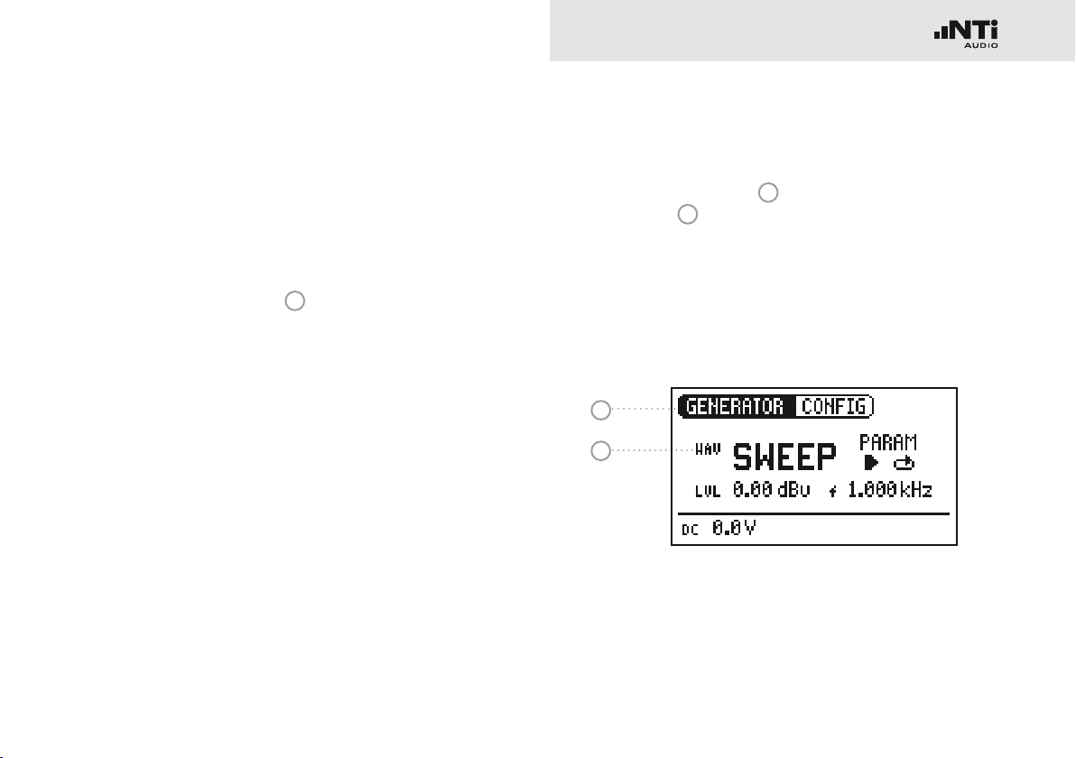
Settings for signal generation
Settings for signal generation
1 2 3
7
6
5
1
Test signal
2
Start / Stop for certain test
signals
3
Setting up the parameters
4
Single / continuous mode
for certain test signals
5
Output frequency
6
Units for the output level
7
Output level
4
Page 10

10
Display of the measured values (MR-PRO)
1 2 3
1
Phantom voltage
2
Balance
3
Impedance
Overview
Page 11

11
Power Supply
Overview
Battery operation
In order to be always able to use the Minirator flexibly, we recommend the use of batteries.
Only use 3x AA, LR6 batteries.•
The battery consumption increases at •
higher level setting as well is based on
the connected load.
During operation, the battery tempera-•
Operation using the mains power supply
You can also connect the Minirator to a mains socket with a
DC power supply unit, which is available for order at NTi Audio. We recommend remaining the batteries inside the instrument.
ture may increase noticeably. This is not
a defect.
The instrument can also be used with re-•
chargeable batteries.
We recommend using the NTi Audio
mains power adapter. This is a switching power supply and leads to increased
noise at the unbalanced output connector.
Alternatively you may utilize a linear power
supply adapter with EU-connector for unbalanced signal applications.
NTi Audio # 600 000 305.
In case you want to make use of a different
DC power supply unit, you must observe
the following specifications:
electrically-isolated, non-earthed linear •
DC power supply unit
2.1 x 5.5 x 9.5 mm plug•
connection •
Voltage from 5 to 9 volts and a current of •
at least 500 mA.
Damage caused by using an inappropriate
external DC supply is not covered by warranty.
Page 12

12
2
1
3
XLR
RCA
~
~
100 Ω
MR2
U/2
U/2
U
100 Ω
0.5 Ω
Overview
Characteristics of the Outputs
The Minirator has two outputs that are wired in parallel:
An unbalanced RCA output and a balanced, non-earthed XLR
output. Both outputs are resistant to externally applied phantom power.
Wherever possible, always use balanced (XLR) connections, as
these have much better immunity to interference than unbalanced connections.
Do not use both outputs at the same
time.
The simultaneous use of both outputs could
lead to a short-circuit in one of the generator
outputs in the connected instrument.
Allocation of the XLR output:
2
3
1
1
PIN 1
2
PIN 2
3
PIN 3
MR2 outputs
Both the RCA and the XLR have a balanced output impedance
of 200 Ohm.
The voltage at the MR2 XLR or RCA output
is less than the set voltage U with low impedance loads.
Example:
A balanced 200 Ohm load impedance matching the 200 ohm output impedance will result in the expected output drop of 6 dB.
Page 13

13
MR-PRO outputs
2
1
3
XLR
RCA
~
~
I<10mA
I<10mA
6.3 Ω
6.3 Ω
MR-PRO
U/2
U/2
U
0.5 Ω
Both the RCA and the XLR have a balanced output impedance
of only 12.5 ohms. The level of the XLR output corresponds
closely to the set output voltage, based upon the low 12.5 ohm
output impedance of the generator.
Behavior with low-impedance loads
The maximum output current of the MR-PRO is 10 mA. If the
connected load consumes more current, the internal regulation
of the MR-PRO reduces the output level. This condition will be
indicated on the screen by the flashing output level display:
Overview
XLR short-circuit between Pin 1 and 3
Commercially available XLR to RCA adapters short-circuit the XLR Pins 1 and 3. Do
not use such adapters with the Minirator!
They will reduce the signal quality, thus use
the RCA output instead.
The MR-PRO is designed for loads down to
600 Ohm. Depending on the output level
and the output frequency, however, the
level is maintained, even for lower load impedances.
Minirator -40dB Adapter
.
For highest quality microphone level signals
we recommend the “Minirator -40dB Attenuator” which is available as an accessory.
It improves the signal to noise ratio for low
level signals by 40 dB.
Order information:
Minirator -40dB Adapter
NTi Audio # 600 000 312
Page 14

14
1.
2.
Getting Started
3. Getting Started
Inserting the Batteries
Only use batteries from the same manu-•
facturer.
Replace the discharged batteries by new •
ones.
Do not mix used and new batteries.•
Open the battery cover.•
Insert three AA-LR6 batteries with the same state of charge, •
paying attention to the +/- marking in the battery compartment.
Close the battery cover once the batteries have been in-•
serted.
You have now successfully inserted the batteries.
Page 15
15
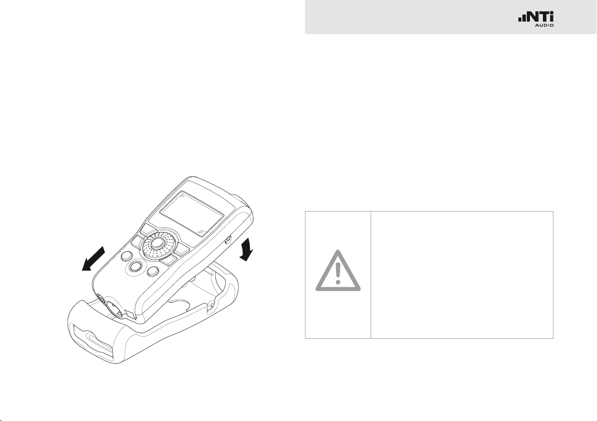
Fitting the Protective Shock Jacket
1.
2.
(MR-PRO only)
Getting Started
With the MR-PRO, you can fit the supplied protective shock
jacket. This will protect the instrument against light impacts
without impairing its easy operation.
Push the lower end of your MR-PRO into the lower end of •
the protective shock jacket.
Push the upper end of the MR-PRO into the protective •
housing.
You have now fitted the protective shock jacket
Damage through impacts / shocks
The protective shock jacket shields your •
MR-PRO against reasonable impacts that
could occur in normal use.
But do not intentionally subject the in-•
strument to extreme stress!
Please do not drop the instrument!•
Damage caused by dropping or impact is •
not covered by warranty.
Page 16

16
2.
1.
3.
Getting Started
Attaching the Hand Strap
To prevent you from accidentally dropping the Minirator, a hand
strap is supplied with the instrument. You can also fit the hand
strap when the protective shock jacket of the MR-PRO has
been fitted.
Pull the hand strap through the opening.•
Pull the rear part of the hand strap through the loop of the •
front part.
Pull the hand strap tight.•
You have now secured the hand strap.
Page 17

17
Connecting the Minirator
1.
2.
1.
2.
Getting Started
XLR connection
Connect the Minirator to your audio device using an XLR •
cable. Note that the locking pin of the plug must be located
on the lower side of the instrument!
You have now connected the Minirator.
RCA connection
Connect the Minirator to the input of the unit to be tested •
using a RCA cable.
You have now connected the Minirator.
Page 18

18
Operation
4. Operation
Switching the Minirator on and off
Switching the Minirator on
To switch the Minirator on, press the “On/Off” button. •
The display lighting is switched on.
You have switched on the Minirator.
Switching the Minirator off
To switch the Minirator off, press the “On/Off” button and •
hold it down for one second.
You have switched off the Minirator.
Navigation in the Menu Bar
The menu bar is divided into two parts. On the left-hand side,
you can choose between the Generator, Cable test (MR-PRO
only), Impedance (MR-PRO only) and System functions.
To do this, select the left side of the menu bar with the rotary •
wheel and confirm with “Enter”.
A selection window opens.
Select the desired function with the rotary wheel.•
Confirm the selection with “Enter”.•
You have now selected the desired function.
You can save and call up configurations on the right-hand side
of the menu bar (see the “Configurations” chapter, MR-PRO
only).
Page 19
19
Selecting a Test Signal
Operation
You have two choices for selecting test signals. You can use
either the direct buttons or the rotary wheel.
Signal selection using the direct buttons
Ensure that GENERATOR•
Press the “Wave” button.•
1
is selected in the menu bar.
A selection menu appears.
Select the desired test signal with the rotary wheel.•
Press “Enter”.•
You have now selected the test signal.
Signal selection using the rotary wheel
Ensure that GENERATOR •
Select “WAV” •
Press “Enter”.•
2
with the rotary wheel.
1
is selected in the menu bar.
A selection menu appears.
Select the desired test signal with the rotary wheel.•
Press “Enter”.•
1
2
You have now selected the test signal.
Page 20

20
Setting the Parameters
Operation
You have two possibilities for setting up the parameters for the
test signals. You can use either the direct buttons or the rotary
wheel.
Setting parameters using the direct buttons
Press the “Level” or “Freq” button.•
You have selected the desired parameter.
Turn the rotary wheel to set the parameter.•
Confirm the setting with the “Enter” button.•
You have now set up the parameter.
Setting parameters using the rotary wheel
Turn the rotary wheel.•
The selected parameters will be marked with a black bar.
Confirm your choice with the “Enter” button.•
The parameter display blinks.
Turn the rotary wheel to set the parameter.•
Confirm the setting with the “Enter” button.•
You have now set the parameter.
Page 21

21
Setting the Sensitivity of the Rotary
Wheel
You can set up the sensitivity (step size) of the rotary wheel. To
do this, proceed as follows:
Select Level • or Frequency with the rotary wheel.
Hold down the “Sens” button.•
The current sensitivity of the rotary wheel will be displayed
1
.
Operation
Turn the rotary wheel to set up the desired sensitivity.•
Release the “Sens” button to accept the desired sensitiv-•
ity.
You have now changed the sensitivity of the rotary wheel.
1
Page 22
22
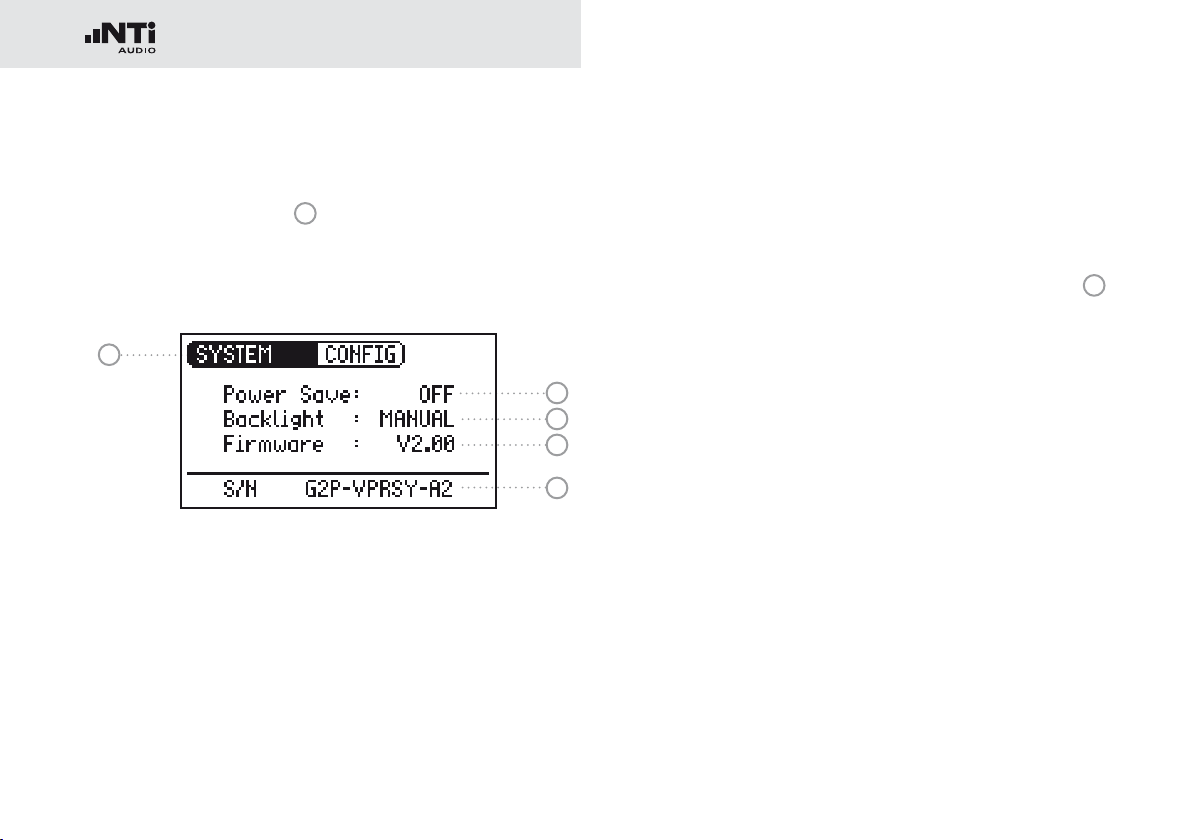
System Settings
Operation
You can adjust various system settings of your instrument. To
do this, switch to System
wheel and confirm with “Enter”.
The possible system settings are displayed:
1
1
in the menu bar using the rotary
2
3
4
5
Power Save
The Power Save mode switches the instrument off if no button
has been pressed within an adjustable time period.
Use the rotary wheel to select the Power Save function •
.
Confirm the selection with the “Enter” button.•
2
The display starts to blink.
Turn the rotary wheel to set the desired time.•
Confirm the entry with the “Enter” button.•
You have now changed the switch-on time of the Power-
Save mode.
Page 23

23
Operation
Backlight
You can choose between “Auto” and “Manual”.
Auto The backlight will be switched on automatically
during operation, and will be switched off again
after a period of time.
Manual Press the “On/Off” button to switch the back-
ground lighting on and off.
To do this, select the Backlight •
wheel.
Press “Enter”.•
3
function with the rotary
The display now changes between “Auto” and “Manual”.
Firmware
Display of the version number, with the possibility of carrying
out an update for the MR-PRO
Firmware”).
Display of the serial number
You can read out the instrument’s serial number
bottom line.
Setting the contrast
Changing the contrast of the screen display.
To do this, proceed as follows:
Hold down the “ESC” button and turn the rotary wheel until •
the desired contrast is obtained.
4
(see chapter “Updating the
5
from the
You have now changed the contrast of the screen display.
Page 24
24
Operation
Configurations (MR-PRO only)
With the MR-PRO, you can store your current instrument settings
as configurations, and can call these up again at a later date.
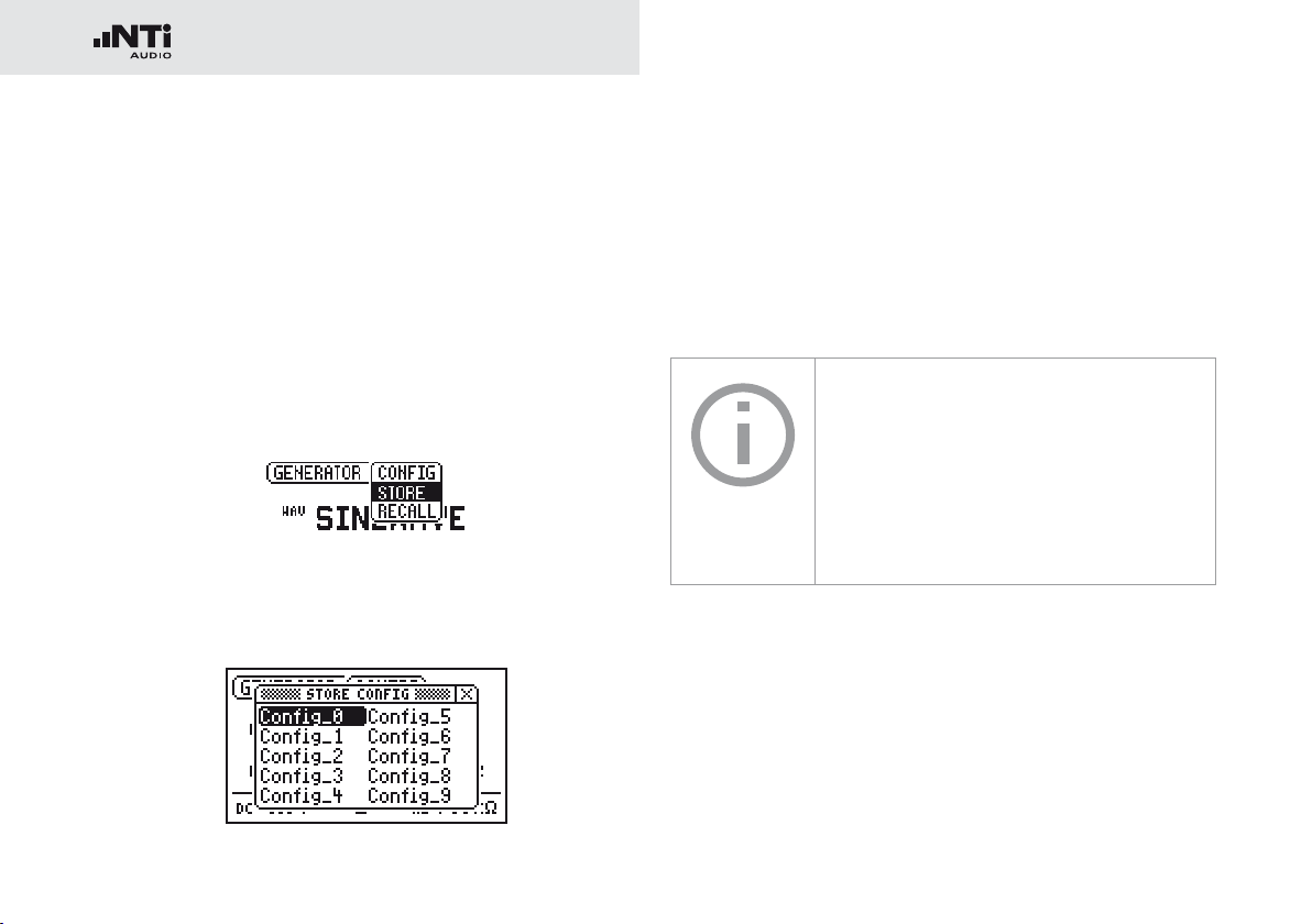
Storing configurations
10 configuration storage locations are available to you.
Using the rotary wheel, select CONFIG in the menu bar.•
Confirm with “Enter”.•
The following menu is opened:
Select STORE and confirm with “Enter”.•
The following selection menu is opened:
Select a memory location with the rotary wheel and store •
your configuration by confirming the selection with “Enter”.
You have now stored the current instrument settings as a
configuration.
In order to easily remember configurations you may rename them.
For altering the file names, connect the
MR-PRO to a computer via USB and rename
the files in the CONFIG folder. Only the first
10 configurations are shown in the display.
Page 25

25
Operation
Calling up configurations
Use the rotary wheel to select CONFIG in the menu bar.•
Confirm with “Enter”.•
The following menu is opened:
Select “Recall” and confirm with “Enter”.•
Select the desired configuration in the Selection menu and •
confirm with “Enter”.
You have now loaded the desired configuration.
Transferring configurations to another device (MR-PRO)
With the MR-PRO, you have the possibility of transferring
stored configurations to another device.
Connect your MR-PRO to a computer via USB.•
A removable memory drive will be indicated on the
computer.
Select the CONFIG sub-folder.•
You will see the stored configurations of your MR-PRO.
Copy this data to your computer.•
Connect another MR-PRO to the computer via USB.•
Copy the previously copied data into the CONFIG sub-folder •
by overwriting the data therein.
You have now transferred configurations from your MR-
PRO to another MR-PRO.
Page 26

26
Test Signals
5. Test Signals
Sine
Characteristics and use
Pure sinusoidal signals are required for almost every audio
measurement. The Minirator provides a wide and adjustable
output level range and selectable output frequencies.
Parameters
Output level
Output frequency
Sweep
Characteristics and use
Sweep signals with a resolution of up to 1/12 octave can be
generated over a freely selectable frequency range. An audio
analyzer like the Minilyzer from NTi Audio can automatically
trigger to this signal sequence to measure the frequency response.
Starting the Sweep signal
Select the “START” symbol •
You can interrupt a running sweep via the „STOP“
symbol.
with the rotary wheel.
Page 27

27
B
t
t
TRIG
t
STEP
f
RES
A
ff
f
t
STEPtSTEPtSTEP
f
STOP
f
START
1 kHz
Sweep Signal modes
Using the “MODE” symbol, you can run the test signal in the
following modes:
Once-only Plays the test signal once
Continuous Repeats the test signal after an adjustable
pause (tPAUSE).
Parameters
Output level
The frequency display is for information only. The
current frequencies will be displayed here once the
SWEEP test signal has been started.
You can configure the signal sequence here.
Test Signals
A The sweep recording starts as soon as the frequency
drops from 1 kHz to fSTART.
B The end of the sweep will be signaled by a falling fre-
quency.
Page 28
28
Test Signals
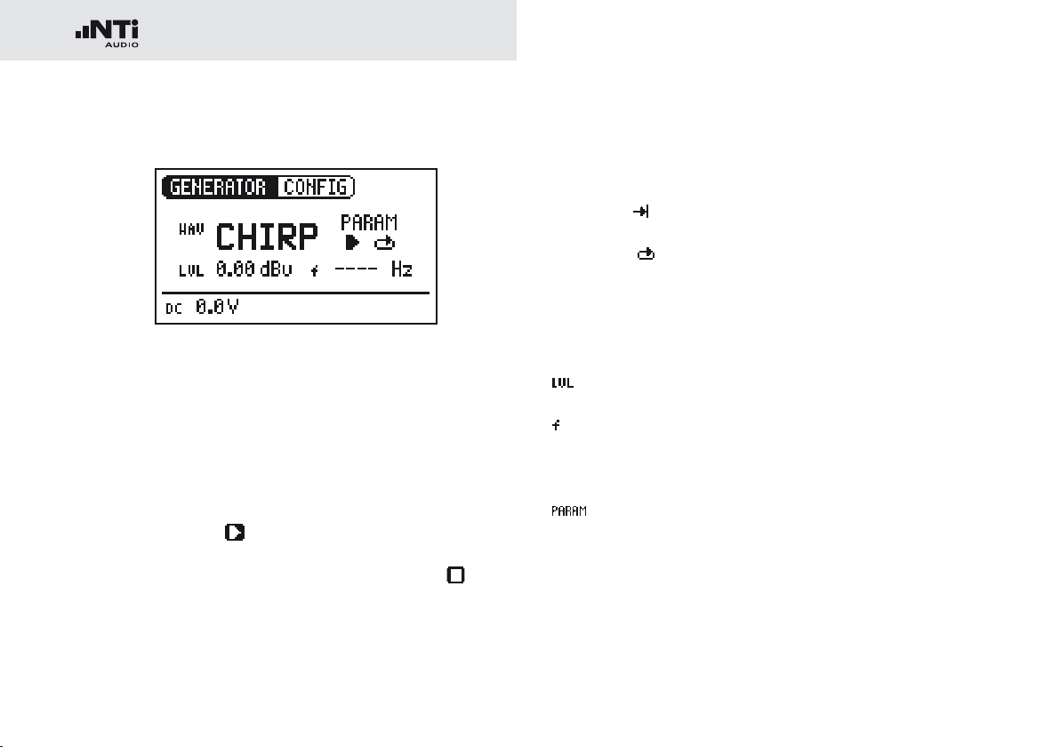
Chirp
Characteristics and use
A Chirp is the name for a signal whose frequency continually
changes over time (also known as continuous sweep). It is used
for the recording of frequency responses, the measurement of
impulse responses and the acoustic assessment of rooms.
Starting the Chirp signal
Select the START •
If this is activated, it turns into a STOP symbol , which
will end the test signal when selected.
symbol with the rotary wheel.
Chirp Signal modes
Using the “MODE” symbol, you can run the test signal in the
following modes:
Once-only
Continuous Repeats the test signal after an adjustable
Parameters
Output level
The frequency display is for information only. The
current frequencies will be displayed here once the
CHIRP test signal has been started.
You can configure the signal sequence here.
Plays the test signal once
pause (tPAUSE).
Page 29

29
t
t
PAUSE
t
SCALE
f
f
STOP
f
START
CHIRP
t
= LIN
t
SCALE
= LOG
Test Signals
Delay Test
Characteristics and use
The Delay Test signal is a specially configured Chirp signal. It
Fading in and out of any Chirp signal generates spurious frequency components,
leading to ripple in the frequency response.
The Chirp sequences of the MR-PRO / MR2
are optimized for ripple of ± 0.2 dB maximum.
Parameter combinations resulting higher
ripple are automatically corrected during input.
enables to setup delay lines in combination with the NTi Audio
Acoustic Analyzers. You can find further information in the ap-
plication notes and user manuals of acoustic analyzers.
Parameters
Output level
Page 30

30
Test Signals
Pink Noise
1
2
Characteristics and use
The Pink Noise test signal has a high spectral density, an infinite
period (> 100 years) and 20 kHz bandwidth. Pink Noise is used
as a reference signal for the layout of loudspeaker systems
(PA systems), whereby a Real Time Analyzer (RTA) is used to
execute the required measurements.
When operated in the intermittent mode, Pink Noise forms the
basis for reverberation time measurements.
Operation
You can choose between the following test signal modes with
the MOD setting
CONT Generates a continuous test signal.
Generates an intermittent test signal.
Parameters
Output level
1
:
You can determine the cycle times of the intermittent signal with the CYC setting
(3/3 = 3 seconds of signal and 3 seconds pause.)
These settings have no effect in the continuous
mode.
2
.
Page 31

31
Test Signals
White Noise
Characteristics and use
The White Noise test signal has a high spectral density,
Gaussian amplitude distribution and an infinite period (> 100
years). White Noise is used for all measurements with FFT
analyzers, and has a constant signal power per Hertz and a
20 kHz bandwidth.
Parameters
Output level
Polarity
Characteristics and use
The sawtooth test signal is ideally suited for checking the polar-
ity of loudspeakers. The NTi Audio audio analyzers detect this
signal and determine the polarity.
Parameters
Output level
The frequency display is for information only. The frequency cannot be adjusted.
Page 32

32
Test Signals
Wave File Player (MR-PRO only)
1
2
Characteristics and use
You can play back your own test sequences with the MR-PRO.
The test sequences will be repeated automatically and without
pauses. For a better overview, Wave files are organized in subfolders.
The MR-PRO is already equipped with a series of demo sequences in the WAV file format. You can create a link to a computer at any time via the USB interface and can exchange existing wav-files or add new ones.
Possible applications
Possible applications include, for example:
Identification generator in the broadcasting sector•
Musical signals for the assessment of PA systems•
Playing back complex test signals•
Selecting a folder
Select the Symbol folder •
Confirm with “Enter”.•
Select the desired folder with the rotary wheel.•
Confirm with “Enter”.•
1
with the rotary wheel.
You have now changed the current playback folder.
Selecting a Wave file
Use the rotary wheel to select the Symbol file •
Confirm with “Enter”.•
Select the desired WAV file with the rotary wheel.•
Confirm with “Enter”.•
2
The wav-file will be played.
.
Page 33

33
Test Signals
Default wav-files
The factory default wav-files are•
Ansagen: Anpassen (German) •
Testsequenz (German)
Messages: Adjust (English)•
Occupied (English)
Test sequence (English)
Signals: NTi Audio STI-PA•
Sounds: Drum1•
Drums2
Hihat
Sax
Synth1
Further customized wav-files are available for download on the
Minirator support page at “http://my.nti-audio.com”.
Copyright
NTi Audio delivers a set of demonstration
wave files with the MR-PRO. These wave
files may only be replayed with an NTi Audio
instrument (MR-PRO). Any further usage is
forbidden.
Loading your own wav-files
Wave files for the MR-PRO must fulfill the following requirements:
48 kHz sampling frequency•
Mono / Stereo•
16 Bit resolution•
If a wave file does not meet the requirements, the playback stops and the “Mute”
button lights up continuously red. Wav-files
can be converted to the above requirements
by a free software available for download at
www.nti-audio.com.
To load WAV-files, you will need a computer
with the following minimum specifications:
PC with Windows 98SE•
Macintosh computer with OSX•
Connect the MR-PRO to the computer via USB. •
The MR-PRO appears on your computer as a removable
data medium.
Page 34

34
Test Signals
WAVE
FOLDER1 FOLDER2 ...
• Signal1.wav
• Signal2.wav
• ...
• Signal1.wav
• Signal2.wav
• ...
All the sub-folders in the “Wave” folder •
now appear in the folder selection
Add additional sub-folders to this folder
level as required.
If necessary, you can make use of the •
other standard possibilities of a removable data medium. For example, you can
copy wav-files from the MR-PRO onto
your computer or delete unnecessary
files.
The absolute level generated at the out-•
put depends on the modulation as well
as the signal form of the data present in
the WAV file.
Example: A fully modulated sinusoidal •
signal played back at 0 dBF generates an
absolute level of 18 dBu at the output.
1
.
Parameters
Output level
The output level of this test signal is adjusted in
dBF (dB full scale) or %.
Open the “WAVE” sub-folder on the removable medium•
Open one of the sub-folders in the “WAVE” folder.•
Copy the desired files into the folder.•
You have now loaded your Wave files.
Page 35
35
Meas. Functions (MR-PRO only)
6. The Measurement Functions of the MR-PRO
The MR-PRO offers the following measurement functions:
Menu Measurements
Generator Impedance
Phantom Power
Balance
Cabletest XLR cables
Phantom Power
Impedance Impedance + Phase
Apparent Power + Phase
Phantom Power
Balance
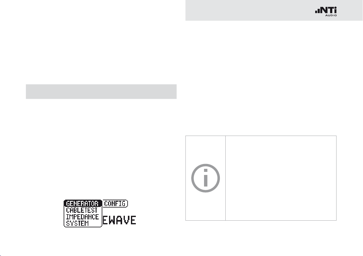
Impedance Test in Generator Mode
The MR-PRO measures phantom voltages and displays impedances and the impedance balance in the SINEWAVE operating
mode. Using the SINEWAVE sinusoidal test signal, the MRPRO measures the load connected to the output between PIN
2 and 3 (RL=R2+R3). The measured values of R2 and R3 will
be displayed by selecting RL with the rotary wheel.
If only R2 or R3 can be measured, RL is replaced by R2 or R3
accordingly.
In the case of balanced connections (XLR), interference radiated onto
the receiver side will be eliminated.
For this to work there must be a balanced
impedance distribution on both signal lines.
In the case of unbalanced impedance distribution, signal interference could occur.
The MR-PRO allows you to test the connections for balance.
Page 36
36
Meas. Functions (MR-PRO only)
2
1
3
R2
R3
XLR
RCA
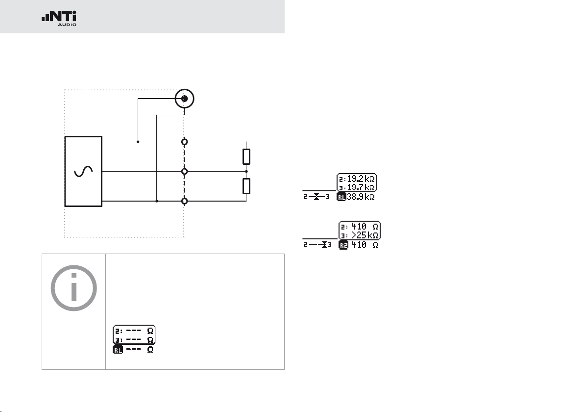
Balance Display
MR-PRO
The impedance and balance measurement
can only be carried out down to a defined
minimum level. If the measurement cannot
be carried out, the display shows:
The balance display allows localizing a number of typical faults,
such as short-circuits and defective cables.
In the case of an unbalanced impedance distribution, the display arrow points to the pin with the higher impedance.
Balanced impedance, R2 = R3
Unbalanced impedance, R3 > R2
Unbalanced load relationships can be analyzed further by selecting the impedance display with the rotary wheel. If the impedance cannot be measured, the display shows “---” instead
of the measurement value.
Page 37

37
Measuring Phantom Power Voltages
2 x 6.8kΩ
V2
V3
2
1
3
+48V
R2
R3
XLR
The phantom voltage is necessary in connection with capacitor microphones in order to operate the impedance converter
located in the microphone as well as for some “active” direct
boxes.
Meas. Functions (MR-PRO only)
MR-PRO
Mischpult
The most common phantom voltage is 48 V and lies on both
Pin 2 and Pin 3 with balanced impedances (see diagram).
1
Unequal phantom voltages on Pin2 and Pin3 of the XLR cable
indicate an error and will be displayed by the blinking of the
phantom voltage display (DC).
You can localize the faulty voltage source by selecting the DC
function
1
with the rotary wheel.
Page 38
38
Meas. Functions (MR-PRO only)
2
1
3
R2 = 1k
R3 = 2k
XLR
Cable
Out
XLR
In
1.
2.
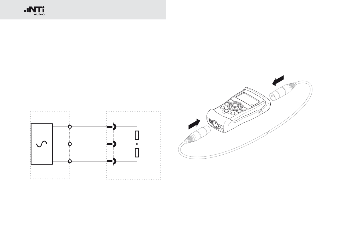
XLR Cable Test
The MR-PRO supports a cable test function that quickly detects damaged XLR cables.
The cable test is based on an impedance measurement. In order to indicate a correctly wired XLR cable, the test routine of
the MR-PRO assumes the following impedances on the output:
MR-PRO
MR-PRO or adapter
To test a cable, proceed as follows
Select the “Cable test” function in the menu.•
Plug the XLR cable into the XLR output (1).•
Plug the other end into the XLR input (2).•
Page 39

39
The following is displayed on the screen:
The cable has not been
plugged in correctly. Check the
cable connection.
The tested cable is defective,
the pins 2 and 3 are crossed.
Other error indications may appear depending on the cables
fault.
The tested cable is OK.
Meas. Functions (MR-PRO only)
Cable Test Plug
For long cables already in place, NTi Audio
offers an optional adapter named “Cable
Test Plug”. Plug one end of the cable into
the Cable Test Plug and the other end of the
cable into the MR-PRO.
Order information:
Cable Test Plug
NTi Audio # 600 000 311
Page 40
40
Meas. Functions (MR-PRO only)
Impedance Test
The impedance test supports the verifications of distributed
loudspeaker installations and shows detailed information of
the connected load.
Connect any unpowered load between Pin 2 and 3 of the XLR
output for best performance.
Damage caused by high voltage
Never connect the instrument to a power
output or any activated distribution system!
MR-PRO 70V/100V Protection
Protects the Minirator MR-PRO against accidentally applied 70V/100V voltages during
impedance or power testing at distributed
speaker systems.
Order information:
MR-PRO 70/100V Protection
NTi Audio # 600 000 313
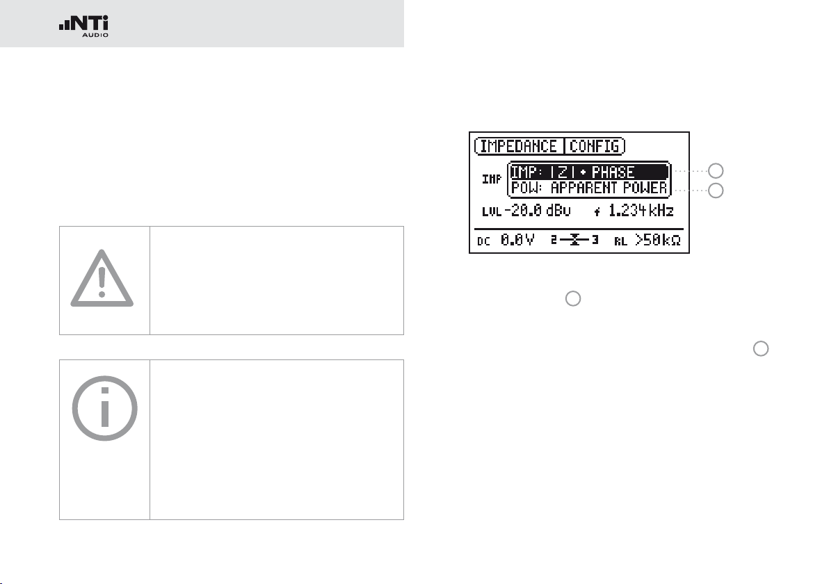
Supported Display Modes
1
2
In the mode |Z| + Phase
ance and the phase is shown.
Based on the measured impedance, the apparent power
which the load would sink when driven with a defined reference voltage is calculated and displayed.
1
the absolute value of the imped-
2
Page 41

41
Meas. Functions (MR-PRO only)
Impedance
2
1
3
How to measure
Connect the load between Pin 2 + 3 of the XLR.•
The absolute value of the impedance •
whether the load is inductive or capacitive
1
, the phase 2 and
3
is displayed.
The output level and frequency may be adjusted as described
earlier in this manual.
If the load is connected unbalanced (e.g. between pin 1 + 2), a
“2” or “3” is displayed below the “IMP” symbol.
Power indication
1
2
3
How to measure
Select the reference voltage of the distributed loudspeaker •
system
1
with the rotary wheel.
Connect the load between Pin 2 + 3 of the XLR.•
The apparent power •
information
3
2
in VA (Volt Ampere) and the phase
is displayed.
Selection of Phase / Power Factor readout
Select “PHS” and press “Enter”.•
The power factor PF = cos (phase angle) is displayed.•
Press “Enter” again.•
You have toggled between Phase and Power Factor dis-
play.
Page 42

42
Updating the Firmware
7. Updating the Firmware
You can find the installed firmware version of your instrument
as follows:
Select “System” in the menu bar.•
Confirm the selection with the “Enter” button. •
The firmware version of the instrument will be displayed.
The firmware update is carried out by connecting your Minirator to a computer via USB and running the PC application
software “MR-Update”.
In order to update the firmware, you will
need a computer with the following minimum specifications:
PC with Microsoft Windows 2000 or •
newer
USB termination•
Connection to web•
Instructions:
1. When updating your Minirator for the first time
Register your instrument at http://my.nti-audio.com (see •
chapter “Further information”). After the registration you
will get the following details at the support page:
Firmware update instruction
-
Overview of new firmware features
Download the software “MR_Up-date“ at the Minirator •
support page.
Install and run “MR_Up-date“•
Follow the instructions shown in “MR_Up-date“. •
2. If you have already updated your Minirator before
Switch your computer online.•
Run the software “MR_Up-date“, which automatically checks •
the NTi Audio website for any new firmware available. No
further manual download is required.
Follow the instructions shown in “MR_Up-date“.•
You have updated the Minirator firmware.
Page 43

43
8. Tips and Troubleshooting
Troubleshooting
Resetting to the factory settings
If the Minirator reacts unexpectedly, a reset to the factory settings might solve the problem.
Switch the instrument off.•
Hold down the “ESC” button and simultaneously operate •
the “On/Off” button.
The confirmation of the reset is displayed on the screen.
Reloading wav-files (MR-PRO only)
You can reload the wave files of the MR-PRO that were installed in the factory.
The files are available at the Minirator support page
“http://my.nti-audio.com”.
Behavior with low-impedance loads
The maximum output current of the MR-PRO is 10 mA. If the
connected load consumes more current, the internal regulation
of the MR-PRO reduces the output level. This condition will
be indicated on the screen by the blinking of the output level
display:
.
PC recognizes Minirator as GPS Camera
The MR-Update Software may not recognize the Minirator at
PCs with Windows 7 installation.
Open the device manager.•
Select with the right mouse button the GPS Camera driver, •
select “Properties“ -> “Driver” -> “Update Driver”.
Select „Search the compute for driver software“.•
Select “Select driver from list …”.•
Select Minirator driver “atm6124.sys ATMEL AT91xxxxx •
Test Board“.
Complete the Minirator driver installation.•
Page 44

44
Troubleshooting
Faults and their correction
Fault Fault finding Cause Remedy
The Minirator does not generate an output signal.
Screen contrast poor. Contrast needs to be
MR-PRO: Wave files are not
played back
MR-PRO indicates no
impedance.
“Mute” button blinks. You have switched the
instrument to Mute.
“Mute” button lights up
continuously.
“Mute” button lights up
continuously.
The lowest line is not
displayed.
You have called up the “Pink
Noise” (PNoise) test signal or
you are in the Pause cycle of
the Chirp test signal.
Non-supported Wave format.
Cable not plugged in correctly.
adjusted.
Non-supported Wave format. Load a supported Wave for-
Output level too low.
Incorrect test signal.
Press the “Mute” button.
Wait until the pause has
ended.
Press the “Start” button.
Load a supported Wav-format.
Plug in the cable correctly.
Press “ESC” and operate the
rotary switch to set the
contrast.
mat.
Increase the output level.
Change to the SINEWAVE
test signal.
Page 45

45
9. Further Information
My NTi Audio
Register your instruments at My NTi Audio and benefit from
the following possibilities:
Free updates for your instruments•
Activation of optional product functions •
Premium access to downloads•
Receive application and product news •
Faster worldwide support •
Tracing support in case of loss or theft•
Calibration support•
Further information
How to Register
Open the web page “http://my.nti-audio.com”.•
You are prompted to login or create your My NTi Audio •
account.
The web page “My NTi Audio Products” opens.•
Select the product type and enter the serial number.•
Confirm with “Register”.•
Now your product is listed in the table “My Products“.•
Congratulations, your NTi Audio product is registered.
Page 46

46
Further Information
Warranty Conditions
International warranty
NTi Audio guarantees the function of its products and the individual components for a period of one year from the date
of sale. During this period, defective products will either be
repaired free of charge or replaced.
Limitations
These guarantee provisions do not cover damage caused by accidents, transportation, incorrect use, carelessness, non-original accessories, the loss of parts, operation with non-specified
input voltages, adapter types or incorrectly inserted batteries.
NTi Audio accepts no responsibility for subsequent damage of
any kind. The warranty will be voided by carrying out repairs
or services by third parties who are not part of an approved
NTi Audio Service Centre.
Statutory Rights
Consumers may have legal (statutory) rights under applicable
national laws relating to the sale of consumer products. This
warranty does not affect your statutory rights. You may assert
any legal rights you have at your sole discretion.
Calibration Certificate
Your NTi Audio instrument has been carefully tested during
production and corresponds to the specifications listed in
“Technical Data”. Calibration certificates for new products are
optional.
NTi Audio recommends annual calibration of the products after the purchase. The calibration provides documented and
traceable measurement accuracy and confirms that your
NTi Audio product meets or exceeds the published specifications. The calibration and adjustment procedures follow the
documentation and traceability requirements of the standard
EN ISO / IEC 17025.
For calibrations kindly follow the service guidelines at
www.nti-audio.com/service.
Service and Repairs
If your product is not functioning correctly or is damaged,
please contact the local NTi Audio partner for assistance. If
the product needs to be returned for service, kindly follow the
service guidelines at www.nti-audio.com/service.
Page 47
47
Further Information
Declaration of conformity
CE / FCC Compliance Statement
We, the manufacturer
NTi Audio AG
Im alten Riet 102, 9494 Schaan
Liechtenstein, Europe
hereby declare that the Minirator MR2 and Minirator MR-PRO
products, approved in 2007, comply with the following standards or other standard documents:
EMC: 2004/108/EG•
Harmonized standards: EN 61326-1 •
Explosive atmospheres (ATEX): 94/9/EG•
This declaration will become invalid if modifications to the instrument are carried out without the written approval of NTi
Audio.
Date: 01.12.2006
Signature:
Information for disposal and recycling
Dispose of your instrument in accordance
with the valid legal environmentally regulations in your country.
Regulations for the European Union and other European
countries with corresponding laws:
The instrument must not be disposed of in the household garbage. At the end of its service life, bring the instrument to a
collecting point for electrical recycling in accordance with the
legal regulations.
Other countries outside the EU:
Contact your respective authorities for waste disposal and follow their regulations.
Position: Technical Director
Page 48

48
Technical Data
10. Technical Data Minirator
MR2 MR-PRO
Outputs Balanced XLR, unbalanced RCA
Inputs DC power supply, USB DC power supply, USB
Signal Wave Forms Sine, Polarity Test Signal, Delay Test Signal,
Wave File Format Sampling frequency:
Resolution:
Output level:
Frequency Setting Range:
Increment:
Accuracy:
Stepped Sweep Function Frequency range:
Increment:
Sweep speed:
Continuous Sweep (Chirp) Function Frequency range:
Increment:
Chirp speed:
Level Setting Units:
Increment:
Output Level Ranges Sine, Sweep, Chirp
White Noise
Pink Noise
Polarity, Delay Test
Flatness RL ≥ 600 Ohm ±0.5 dB ±0.2 dB @ 10 Hz to 12 kHz
Accuracy @ 1kHz ±0.5 dB ±0.2 dB
White Noise (crest factor, PAR* = 3.05 (9.7 dB)),
Pink Noise (crest factor, PAR* = 4.5 (13.1 dB)),
Gated Pink Noise (1 - 9 seconds), Wave File playback (MR-PRO)
dBu, dBV, V
in 1 digit steps
–80 dBu to +8 dBu
–80 dBu to +0 dBu
–80 dBu to –2 dBu
–80 dBu to +6 dBu
phantom power resistant
XLR for cable test
48 kHz
16 Bit, Mono / Stereo
0 dBFS = 18 dBu (sine) acc. to EBU R68
10 Hz to 20 kHz
in 1 digit steps
0.01%
freely selectable
1/1, 1/3, 1/6, 1/12 octave
selectable 0.5 to 5 seconds
freely selectable
Linear / Logarithmic
1 to 99 seconds per cycle
dBu, dBV, V, dBFS, %
in 1 digit steps (e.g. 0.1 dBu)
–80 dBu to +18 dBu
–80 dBu to +10 dBu
–80 dBu to +8 dBu
–80 dBu to +16 dBu
–0.1 dB / +0.3 dB @ 12 kHz to 20 kHz
* PAR = peak-to-average ratio
Page 49

49
Technical Data
MR2 MR-PRO
THD+N 22 Hz to 22 kHz, average,
@ 1 kHz, typical
Output Impedance 200 Ohm (balanced) 12.5 Ohm balanced, Imax = 10 mA
Impedance Measurement Method:
Measurement range:
Accuracy:
Power Calculation Reference voltage 25 V, 35 V, 50 V, 70.7 V,
Phantom Voltage Measurement range:
Accuracy:
USB Functionality Firmware update Firmware update
Flash Memory 512 MByte for storing wave files and
Display Graphical, with back light
Auto-Power-Off 10, 30, 60 minutes or OFF
Batteries 3 x AA Alkaline dry cells or rechargeable equivalents
Battery Life 0 dBu, no load, typical 14 hours 8 hours
Temperature Range 0° to 45° C (32° to 113° F)
Humidity < 90% relative humidity, non-condensing
Protection Rating IP51
Dimensions (LxWxH) 147 x 74 x 41 mm 152 x 81 x 43 mm
Weight including Batteries 250 g (9 oz.) 310 g (11 oz.)
–90 dB (0.0032%) @ 8 dBu,
Noise floor typ. 25 μV
–96 dB (0.0016%) @ 18 dBu,
Noise floor typ. 15 μV
Absolute value Z
4 Ohm to 50 kOhm balanced
2 Ohm to 25 kOhm unbalanced
@ f = 30 Hz to 10 kHz (Sine)
@ Level from –20 to +18 dBu
±10% or ±2Ohm (whatever is higher)
100 V, 140 V, 200 V
0 to 54 V
±3 % or ±0.5 V
Mass Storage Device
configurations
(incl. protective shock jacket)
Page 50

Page 51

Page 52

2000 td 04.14
 Loading...