

Page 1
NTI
NETWORK
R
TECHNOLOGIES
INCORPORATED
1275 Danner Dr
Aurora, OH 44202
www.networktechinc.com
Tel:330-562-7070
Fax:330-562-1999
XTENDEX®Series
USB-C5
USB-C5-CE
USB EXTENDER
Installation and User Guide
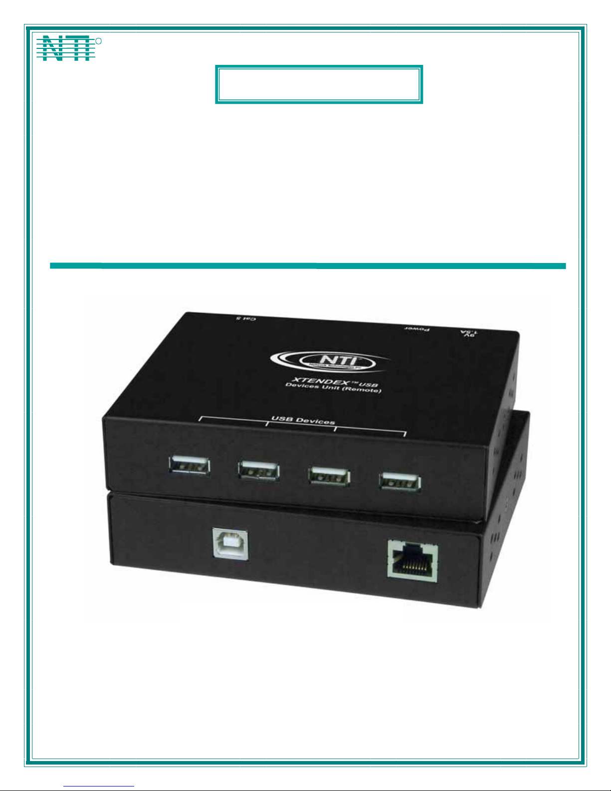
Front and rear view of USB-C5-CE Devices Unit
MAN022 Rev Date 02/20/2007
Page 2

TRADEMARK
XTENDEX is a registered trademark of Network Technologies Inc in the U.S. and other countries.
COPYRIGHT
© 2002-2007 Network Technologies Inc. All rights reserved. No part of this publication may be reproduced, stored in a retrieval
system, or transmitted, in any form or by any means, electronic, mechanical, photocopying, recording, or otherwise, without the
prior written consent of Network Technologies Inc, 1275 Danner Drive, Aurora, Ohio 44202.
CHANGES
The material in this guide is for information only and is subject to change without notice. Network Technologies Inc reserves the
right to make changes in the product design without reservation and without notification to its users.
Shielded CAT 5,5e, or 6 cable must be used to connect to the CAT5 ports in order to meet CE emission and immunity
requirements.
CE Statement
We, Network Technologies Inc, declare under our sole responsibility that the USB-C5-CE is in conformity with European Stand ard
EN55022.
i
MAN022 Rev Date 02/20/2007
Page 3

TABLE OF CONTENTS
Introduction......................................................................................................................................................................1
Glossary.......................................................................................................................................................................1
Limitations....................................................................................................................................................................1
Materials ......................................................................................................................................................................1
Preparation for Installation ..............................................................................................................................................2
Features and Functions...................................................................................................................................................3
Installation .......................................................................................................................................................................4
The CPU Unit (Local)...................................................................................................................................................4
The Devices Unit (Remote) .........................................................................................................................................5
Plug-in and Boot Up.....................................................................................................................................................6
Technical Specifications..................................................................................................................................................7
General Specifications.................................................................................................................................................7
Power Requirements...................................................................................................................................................7
Interconnection Cable Wiring Method .........................................................................................................................8
Troubleshooting...............................................................................................................................................................8
Problem........................................................................................................................................................................8
Cause...........................................................................................................................................................................8
Solution........................................................................................................................................................................8
Warranty Information.......................................................................................................................................................9
TABLE OF FIGURES
Figure 1- Connect the CAT5 USB Extender to a CPU.......................................................................................................................4
Figure 2- Connect devices to the CAT5 USB Extender .....................................................................................................................5
Figure 3- Attach the CAT5 cable to the Devices Unit.........................................................................................................................5
Figure 4- Connect the AC adapter to the Devices Unit...................................................................................................................... 6
ii
MAN022 Rev Date 02/20/2007
Page 4

NTI XTENDEX USB EXTENDER
INTRODUCTION
The NTI USB-C5 USB Extender was designed to allow the connection of up to 4 USB devices (keyboards, mice,
cameras, etc.) to a USB CPU using unshielded CAT5 cable. It acts as a remote USB HUB. The USB-C5 USB Extender is selfpowered and designed for high power devices.
It is extremely simple to install and has been thoroughly tested to insure re liable performance. Through the use of Category 5
unshielded twisted-pair cable it is possible to economically increase the range of the USB.
Available Option
• Model USB-C5-CE has been tested and certified to meet CE emission and immunity requirements.
Glossary
• bus-powered- devices powered from the USB cable- .5A (500mA) maximum
• self-powered- devices powered from a local source (such as batteries or transformer) requiring only negligible
current draw from the USB cable
Limitations
The total length of the CAT5 cable between a USB CPU and devices con nected to the USB-C5 USB Extender must not exceed
100 feet.
Note: "total length" includes the USB cable from the CPU + the CAT5 cable + cable length to any device.
(For bus powered devices only- exclude self-powered devices from calculation)
Materials
Materials Supplied with this kit:
• NTI USB-C5 (or USB-C5-CE) USB Extender Devices Unit (Local)
• NTI USB-C5 (or USB-C5-CE) USB Extender CPU Unit (Remote)
• 120VAC or 240VAC at 50 or 60Hz-9VDC/1.5A AC Adapter
• Line Cord, country specific
• USB-AB-1M Cable
• This owner's manual
Materials Not Supplied, BUT REQUIRED:
• CAT5 Cable
1
Page 5

NTI XTENDEX USB EXTENDER
PREPARATION FOR INSTALLATION
• A location should be chosen for the Devices Unit such that cables from the supported devices will reach it.
• The CAT5 cables must be run to the locations where the Devices Unit and CPU Unit will be mounted. Be careful to route the
cables away from any sources of magnetic fields or electrical interference that might reduce the quality of the signal (i.e. AC
motors, welding equipment, etc.) .
NOTE: The installer must ensure that all CAT5 cable between the USB-C5 Extender CPU unit and Devices Unit is of the
straight-through type and not
• A 120V or 240V electrical outlet (depending on the AC adapter being used) must be installed close en ough to the mounting
location of the Devices Unit to plug the AC adapter into.
• All cables should be installed in such a way that they do not cause stress on their connections to the equipment. Exten ded
lengths of cable hanging from a connection may interfere with the quality of that connec tion. Secure cables as needed to
minimize this.
• Properly shut down and disconnect the power from the CPU and devices to be extended. If other equipment is involved
whose connections are being interrupted, be sure to refer to the instruction manuals for that equipment for proper
disconnection and re-connection procedures before proceeding.
crossed.
Front and rear view of USB-C5 Devices Unit
(non-CE)
2
Page 6

NTI XTENDEX USB EXTENDER
1
Front View of USB-C5 DEVICES UNIT Rear View of USB-C5 DEVICES UN IT
USB Devices
Devices Unit (Remote)
USB
XTENDEX
Cat 5
R
NTI
Network Technologies Inc
9VDC 1.5A
Power
Network Technologies Inc
NTI
R
XTENDEX
Devices Unit (Remote)
USB
Power
9VDC 1.5A
Cat 5
USB Devices
2 3 4
FEA TURES AND FUNCTIONS
1. Power- LED to indicate the USB Extender has power to operate
2. 9VDC 1.5A- connection jack for the AC adapter
3. CAT5- RJ45 female connector- for attachment of the CAT5 extension cable to/from the CPU Unit
4. USB DEVICES- USB type A female receptacles- for connection of user USB device(s)
5. CPU x- USB type B female receptacles-for connection of USB device cable from CPU
6. CAT5- RJ45 female connector- for attachment of the CAT5 extension cable to/from the Devices Unit
Front Vi ew of USB-C5 CPU UNIT
CPU Unit (Local)
USB
USB CPU Cat 5
5
XTENDEX
Network Technologies Inc
NTI
R
6
3
Page 7

NTI XTENDEX USB EXTENDER
INSTALLATION
The CPU Unit (Local)
1. Position the CPU Unit such that the CAT5 cable, the AC adapter power cable, and the USB cable from the CPU can
reach the CPU Unit.
2. Connect the USB type B male end of the USB-AB-1M cable to the USB type B female port on the CPU Unit (Local).
(See Fig.1.)
3. Connect the USB type A male end of the USB-AB-1M cable to a USB type A port on the CPU.
(See Fig.1.)
4. Connect the CAT5 cable to the “CAT5” port on the CPU Unit (Local). (If an RJ45 wall outlet is being
used, connect the other end of the extension cable to it.) When properly inserted the cable end should
snap into place. (See Fig. 1.)
!
WARNING: Never connect the USB-C5 Extender to an Ethernet card, Ethernet router, hub or switch or other
Ethernet RJ45 connector of an Ethernet device. Damage to devices connected to the Ethernet may result.
USB Type A Female
Figure 1- Connect the CAT5 USB Extender to a CPU
Note: Disconnection of the CAT5 cable from either the Remote or Local unit may cause u n expected behavior of the
connected CPU (i.e. Windows blue screen lock-up, system reboot, etc.).
Rear View of CPU
USB Type A Male
USB-AB-1M
USB
R
USB CPU Cat 5
USB Type B Male
4
CPU Unit (Loca l)
XTENDEX
Network Technologies Inc
NTI
USB Type B Female
RJ45 Female
CAT5 Cable to D evices Unit
Page 8

NTI XTENDEX USB EXTENDER
The Devices Unit (Remote)
1. Position the Devices Unit such that the CAT5 cable, the devices to be used, and the AC adapter power
connector can each reach the Devices Unit.
2. Connect the device cable(s) to the USB
port(s) on the Devices Unit. (See Fig. 2.)
USB Type A Fe male
Cat 5
Devices Unit (Remote)
NTI
Network Tec h nologie s I nc
XTENDEX
USB Devices
R
USB
USB Keyboard
9VDC 1.5A
Power
USB Type A
Male Connectors
USB Type A male
USB
Mouse
Figure 2- Connect devices to the CAT5 USB Extender
3. Make sure the CAT5 cable has been installed in accordance with the
"Preparation for Installation" instructions on page 2. Connect the CAT5 cable to
the "CAT5" port on the Devices Unit. (If an RJ45 wall outlet is being used, connect
the other end of the extension cable to the RJ45 wall outlet.) When properly
inserted the CAT5 cable end should snap into place. (See Fig. 3.)
WARNING: Never connect the USB-C5 Extender to an Ethernet card,
!
Ethernet router, hub or switch or other Ethernet RJ45 connector of an
Ethernet device. Damage to devices connected to the Ethernet may
result.
Power
9VDC 1.5A
USB
USB Devices
Devices Unit (Remote)
XTENDEX
Network Technologies Inc
NTI
R
Cat 5
CAT5 Cable to CPU Unit
Figure 3- Attach the CAT5 cable to the Devices Unit
5
Page 9

NTI XTENDEX USB EXTENDER
Plug-in and Boot Up
1. Connect the AC adapter power connector to the 9VDC port on the Devices Unit. Make sure the power
connector is properly inserted. (See Fig. 4.)
2. Plug the AC adapter into a power outlet. The power LED on the Devices Unit (see Fig. 4) should illuminate
indicating that a proper power connection has been made.
USB
Power LED
9 VDC
Adapter
ADAPTER
Power
9VDC 1.5A
Barrel
Power Connector
9VDC @ 1.5A OUT PU T
(Outside
barrel)
2.1 mm x 5.5 mm Female
(Inside
barrel)
USB Devices
Devices Unit (Remote)
XTENDEX
Network Techn ologies Inc
NTI
R
Cat 5
Figure 4- Connect the AC adapter to the Devices Unit
3. Turn ON the CPU. The devices should each react as if they were directly connected to the CPU.
6
Page 10

NTI XTENDEX USB EXTENDER
TECHNICAL SPECIFICATIONS
General Specifications
Interconnect Cable CAT 5 Solid UTP EIA/TIA 568 B wiring w/RJ45 connectors
Devices Unit (Remote) Power 120 or 240 VAC / 9VDC / 1.5A AC Adapter
CPU Unit (Local) Power self-powered unit via CAT5 extension cable
USB-C5 USB Extender (Devices Unit and CPU unit
combined ) current draw (without any bus-powered
devices connected)
USB TYPE B USB TYPE A
PIN # SIGNAL
1 +VCC 1 +VCC
2 - DATA 2 - DATA
3 +DATA 3 +DATA
4 GND 4 GND
Mating face of a USB Type B Female
Mating face of a USB Type A Female
21
43
.3A @ 9VDC
PIN # SIGNAL
1
2
34
9 VDC
Adapter
ADAPTER
Barrel
Power Connector
9VDC @ 1.5A OUTPUT
(Outside
barrel)
2.1 mm x 5.5 mm Female
(Inside
barrel)
Power Requirements
The NTI USB-C5 Extender is designed to operate with up to four devices whose combined current consumption cannot exceed
1.2A. In most applications, the combined current consumption of the devices attached will not exceed 1.2A. To determine how
much current the application will require, find the amount of current each device uses (usually printed on a lab el on the device as
xxA or xxmA) and add them up. If the total current consumption of the devices to be connected exceeds 1.2A (or 1200mA), do
not connect all devices at the same time to the USB-C5 Extender. Connect only those devices whose combined curr ent
consumption is equal to or less than 1.2A (1200mA).
7
Page 11

NTI XTENDEX USB EXTENDER
Interconnection Cable Wiring Method
The CAT5 connection cable between the Devices Unit and CPU Unit is terminated with RJ45 connectors and must be wired
according to the EIA/TIA 568 B industry standard. Wiring is as per the table and drawing below.
WARNING: It is imperative that the cable used for interconnection is of the straight-through type and not crossed.
Pin # Wire Color Pair Function
1 White/Orange 2 T
2 Orange 2 R
3 White/Green 3 T
4 Blue 1 R
5 White/Blue 1 T
6 Green 3 R
7 White/Brown 4 T
8 Brown 4 R
Pair 2 Pair 1
T
1
+
(View Looking into RJ45 female)
Pair 3
Pair 4
T
R
R
T
3
2
4
5
+
-
-
+
R
R
T
8
6
7
-
+
-
TROUBLESHOOTING
Each and every piece of every product produced by Network Technologies Inc is 100% tested to exacting specifications. We
make every effort to insure trouble-free installation and operation of our products. If problems are encountered while installing this
product, please look over the troubleshooting chart below. If an answer is not found in the chart, check the FAQs (Frequently
Asked Questions) at our website at www.networktechinc.com
in US & Canada or 330-562-7070 (worldwide). We will be happy to assist in any way we can.
or contact NTI directly for help at 800-742-8324 (800-RGB-TECH)
Problem Cause Solution
Devices Unit power LED does
not illuminate
Extender is shown as a
Generic USB Hub with a
green "?" next to it in the
device manager (WIN ME)
CPU will not recognize the
mouse when the mouse is
plugged into the extended
keyboard USB port
Power supply is not connected or
plugged-in.
Windows didn't know the exact driver
to install but installed a compatible
driver
Some MAC CPUs (i.e. Mini-MAC)
have drivers that won’t see devices
connected to a USB hub (the
keyboard) that is also connected to a
USB hub (the XTENDEX).
Make sure outlet is live and AC adapter is plugged
in. Also make sure power jack is fully connected to
the Devices Unit.
This is normal. No action is necessary. For more
information see Microsoft Knowledge
Base Article 275012. http://support.microsoft.com
Plug mouse directly into the USB port on the
XTENDEX Remote unit.
8
Page 12

NTI XTENDEX USB EXTENDER
WARRANTY INFORMATION
The warranty period on this product (parts and labor) is two (2) years from the date of purchase. Please contact Network
Technologies Inc at (800) 742-8324 (800-RGB-TECH) or (330) 562-7070 or visit our website at
information regarding repairs and/or returns. A return authorization number is required for all repairs/returns.
MODEL : USB-C5
USB-C5-CE
http://www.networktechinc.com for
SERIAL NO:
DATE: __
INSPECTED BY:
SERIAL NO:___________
DATE:________________
INSPECTED BY:____________
DEVICES UNIT CPU UNIT
Man022 Rev 2-20-07
9
 Loading...