

Page 1
®
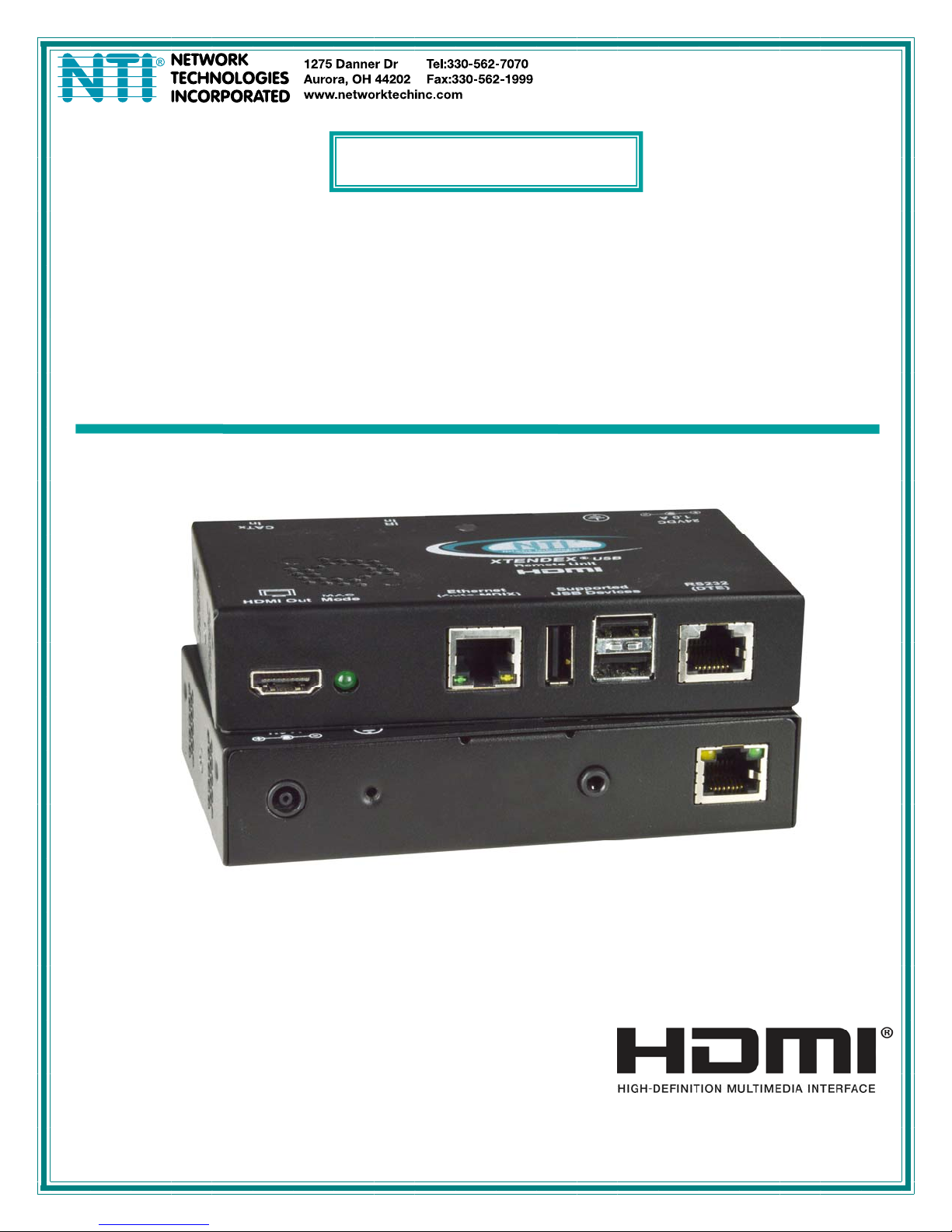
XTENDEX
Series
ST-C6USBH(E)-HDBT
328 FOOT HDMI USB KVM Extender over
HDBaseT
Installation and Operation Manual
ST-C6USBHE-HDBTRemote and Local Unit
MAN149 Rev Date 1/5/2015
Page 2
TRADEMARK
XTENDEX is a registered trademark of Network Technologies Inc in the U.S. and other countries.
COPYRIGHT
Copyright © 2008,2015 by Network Technologies Inc. All rights reserved. No part of this publication may be reproduced, stored
in a retrieval system, or transmitted, in any form or by any means, electronic, mechanical, photocopying, recording, or otherwise,
without the prior written consent of Network Technologies Inc, 1275 Danner Drive, Aurora, Ohio 44202.
CHANGES
The material in this guide is for information only and is subject to change without notice. Network Technologies Inc reserves the
right to make changes in the product design without reservation and without notification to its users.
Note: CATx connection cable used between NTI XTENDEX Series Local and Remote or any XTENDEX Series products
should not be run underground, outdoors or between buildings.
WARNING: Outdoor or underground runs of CATx cable could be dangerous and will void the warranty.
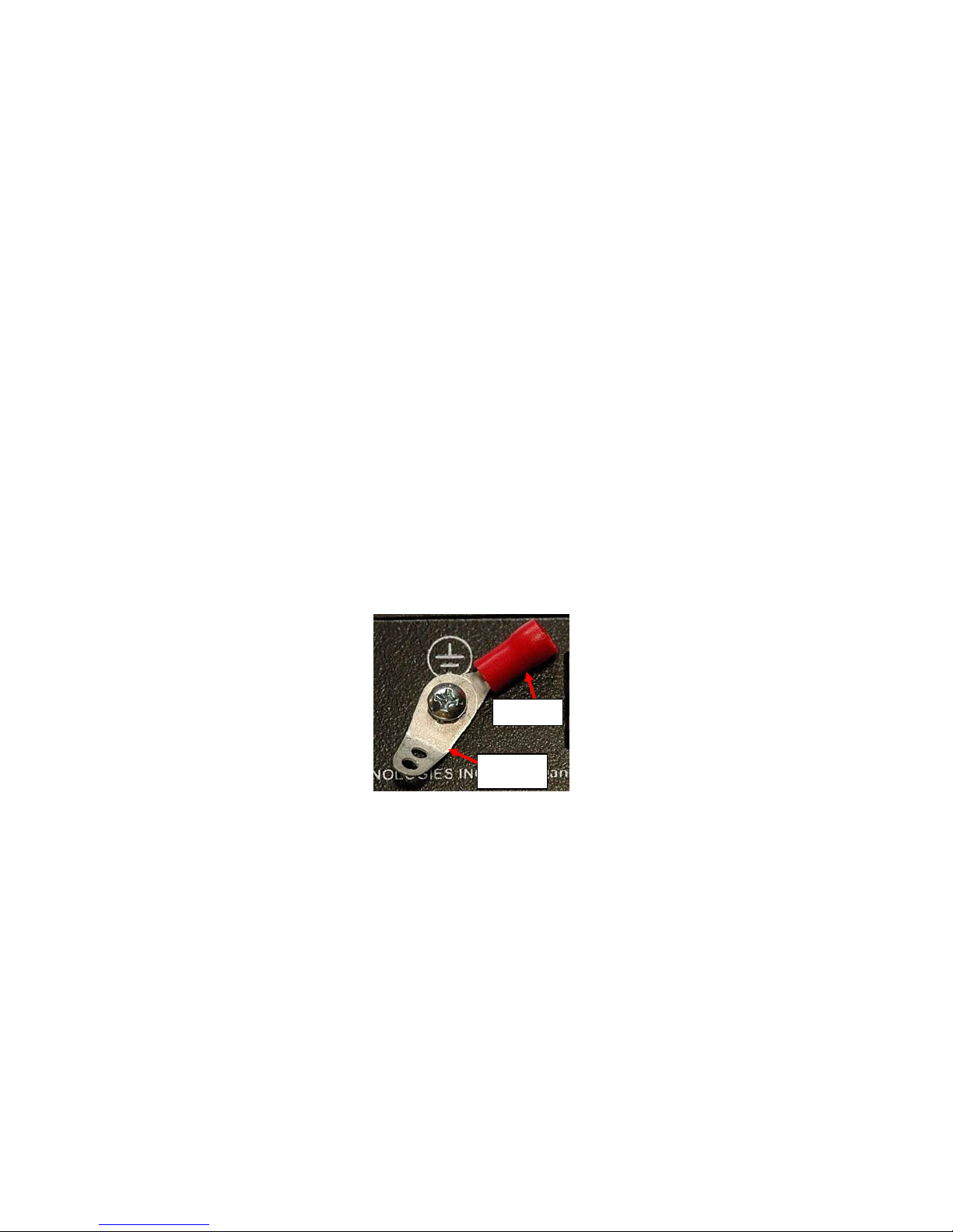
This product is equipped with grounding hardware to prevent interference from sources of electrical noise that could inte rfere with
the normal operation of the XTENDEX or damage it. Use either the crimp-on lug or solder terminal to secure a properly grounded
wire to the XTENDEX.
Crimp-on
Solder
terminal
i
Page 3

TABLE OF CONTENTS
Introduction......................................................................................................................................................................1
Materials..........................................................................................................................................................................2
Connectors and LEDs.....................................................................................................................................................3
Limitations .......................................................................................................................................................................4
Preparation for Installation ..............................................................................................................................................4
Installation .......................................................................................................................................................................5
Installing The Local Unit ..............................................................................................................................................5
100BaseT Support Option........................................................................................................................................5
Installing The Remote Unit ..........................................................................................................................................6
Connect the CATx Cables...........................................................................................................................................7
Plug-in and Boot Up.....................................................................................................................................................7
Infrared Control ...............................................................................................................................................................8
MAC Mode.......................................................................................................................................................................9
Firmware Upgrade Procedure.......................................................................................................................................10
Requirements ............................................................................................................................................................10
Prepare to Upgrade the Firmware.............................................................................................................................11
Upgrade Procedures..................................................................................................................................................12
Upgrade the Local Controller Firmware..................................................................................................................12
Upgrade the Remote Controller Firmware..............................................................................................................13
Technical Specifications................................................................................................................................................15
Interconnection Cable Wiring Method...........................................................................................................................15
Troubleshooting.............................................................................................................................................................17
Warranty Information.....................................................................................................................................................17
TABLE OF FIGURES
Figure 1- Connect the XTENDEX Local Unit to the computer............................................................................................................5
Figure 2- Connect the extended components to the Remote Unit.....................................................................................................6
Figure 3- Connect CATx cable...........................................................................................................................................................7
Figure 4- Connect the AC adapter to either the Remote Unit or the Local Unit .................................................................................7
Figure 5- Connect IR Emitter and Receiver.......................................................................................................................................8
Figure 6- MAC Mode LED..................................................................................................................................................................9
Figure 7- Connect PC for firmware upgrade....................................................................................................................................11
Figure 8- View looking into RJ45 female..........................................................................................................................................15
ii
Page 4

NTI XTENDEX 328 Foot HDMI USB KVM Extender over HDBaseT
INTRODUCTION
The XTENDEX® ST-C6USBH-HDBT HDMI USB KVM Extender over HDBase-T provides remote KVM (USB keyboard, USB
mouse and HDMI monitor) access to a USB computer up to 328 feet away over a single CAT5e/6/7 cable using HDBase-T
technology. Each video extender consists of a local unit that connects to a computer, and a remote unit that connects to a
keyboard, monitor and mouse.
The XTENDEX Series Extender is extremely simple to install and has been thoroughly tested to insure reliable performance.
Through the use of CAT5e/6/7 (CATx) cable it is possible to economically increase the flexibility of an entertainment system. Here
are some of the features and ways this can benefit you:
• Transmits an uncompressed high speed HDMI signal over one CAT5e/6/7 cable.
• Supports HDTV resolutions to 1080p and computer resolutions to 1920x1200.
• Only one power supply is necessary to power both the local and remote units.
• HDMI features supported:
o x.v.Color, sYCC601 color, Adobe RGB Color and Adobe YCC601 color
o Dolby TrueHD, DTS-HD Master Audio, Dolby Digital, and DTS
o Bandwidth up to 154 MHz (3.76Gbps)
o Support for CEC (consumer electronic control) compatible devices.
o Lip Sync
• HDCP compliant.
• Supports the DDC2B protocol.
• Full Infrared Remote (IR) control of HDMI source from remote HDTV using existing source remote control.
• USB ports for keyboard and mouse.
o Keyboard and mouse are hot-pluggable.
o Keep-alive keyboard/mouse emulation for fla wless operation.
• Features an additional USB port on the remote unit for a touch screen monitor, interactive whiteboard, CAC card reader,
or USB printer (requires firmware version 1.1 or later).
• Bi-directional RS232 interface.
• Integrated mounting brackets for easy surface/wall mounting.
• High quality, rugged steel construction with durable powder coat finish.
Optional: 100BaseT support on the transmitter and receiver for connecting standard network devices such as 100Bas e-T
routers and hubs. (Add an “E” to the part number- order ST-C6USBHE-HDBT)
1
Page 5
NTI XTENDEX 328 Foot HDMI USB KVM Extender over HDBaseT
MATERIALS
Materials Included with ST-C6USBH(E)-HDBT kit:
9 NTI XTENDEX Local Unit
9 NTI XTENDEX Remote Unit
9 1-HD-3-MM 3 foot male-to-male HDMI video cable
9 1-100VAC to 240VAC at 50 or 60Hz-24VDC/2.5A AC Adapter
9 1- Power Cord- country specific
9 3 Foot IR-EMITTER (IR-EMTR-3)
9 3 Foot IR-RECEIVER (IR-RCVR-3)
9 1-CB4306 USB2-AB-1M-5T 1 meter USB 2.0 male type A-male type-B transparent cable
9 CT6182 DB9 Female-to-RJ45 Female adapter
9 CT6488 DB9 Male-to-RJ45 Female adapter
9 2-CB4352 5 foot RJ45-to-RJ45 CAT5 patch cable
9 CD containing a pdf of this manual
Additional materials may be required but are not supplied:
¾ CAT5e solid UTP ; 6/6a solid UTP; CAT7 solid STP (CATx) twisted-pair cables terminated with RJ45 connectors wired
straight thru- pin 1 to pin 1, etc. (see page 15 for proper EIA/TIA 568 B wiring method)
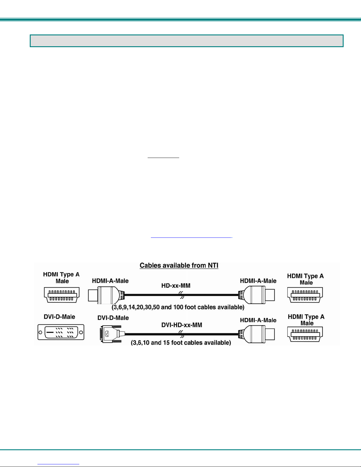
¾ HDMI male-male cable to connect a HDMI source or display (Order NTI # HD-xx-MM where xx=3, 6, 9,14,20,30, 50 and 100
foot cable).
¾ DVI-D male to HDMI-A male single link cable to connect a DVI source or display (Order NTI # DVI-HD-xx-MM where xx=3, 6,
10, or 15 foot cable)
Always use the shortest possible cable for best performance.
Contact your nearest NTI distributor or NTI directly for all of your KVM needs at 800-RGB-TECH (800-742-8324) in US & Canada
or 330-562-7070 (Worldwide) or at our website at http://www.networktechinc.com
and we will be happy to be of assistance.
2
Page 6
NTI XTENDEX 328 Foot HDMI USB KVM Extender over HDBaseT
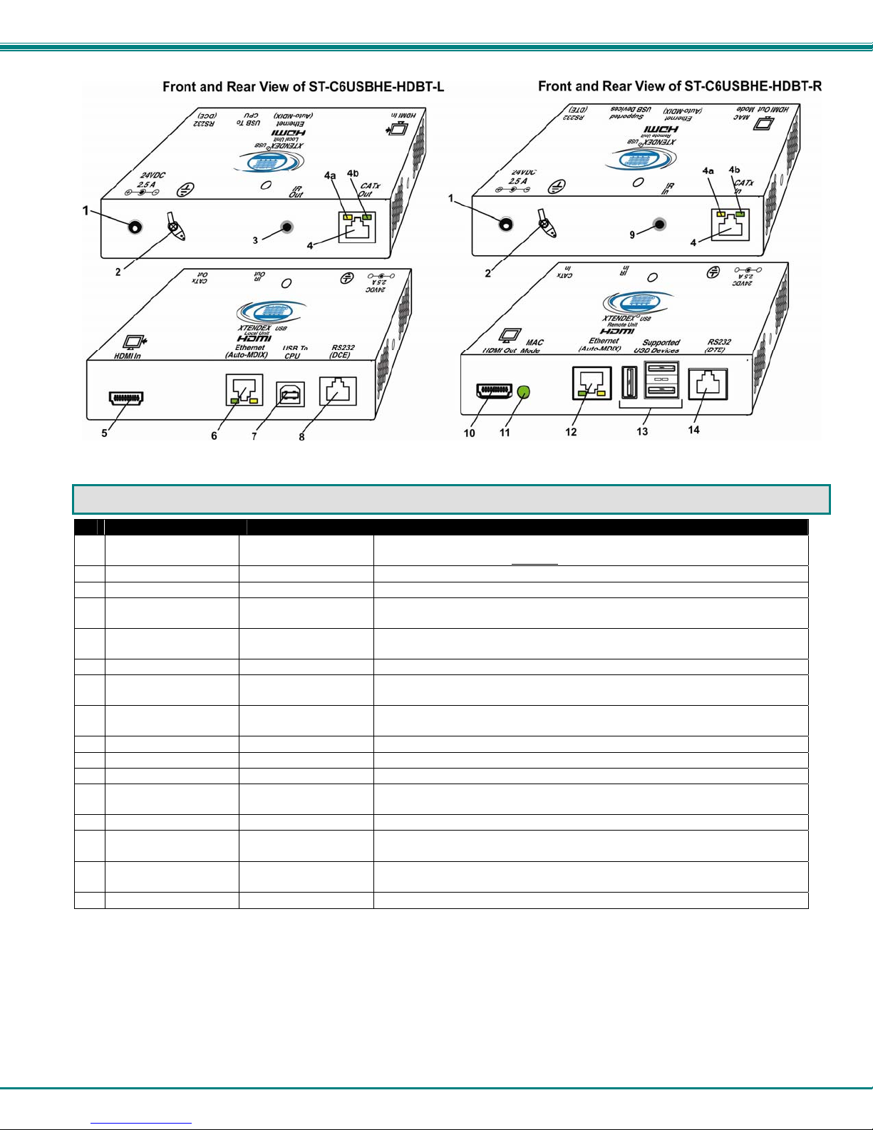
CONNECTORS AND LEDS
#
LABEL CONNECTOR DESCRIPTION
1 24VDC- 2.5A
2 Ground
3 IR Out
4 CATx In
4a Yellow LED -- traffic indicator- illuminates when there is communication between the
4b Green LED -- power indicator- illuminates when power has been supplied to the unit
5 HDMI In
6 Ethernet
7 USB to CPU
8 RS232 (DCE)
9 IR In
10 HDMI Out
11 MAC Mode
12 Ethernet
13 Supported USB
Devices
14 RS232 (DTE)
1.0mm Power Jack connection jack for the AC adapter (only the Local or the Remote Unit
needs to be powered, not both)
Crimp and solder for connecting earth ground to case
3.5mm Stereo Jack for connecting the IR Emitter
RJ45 connector for connecting the CAT5e/6/6a/7 cable between the Local and Remote
units
local and remote units.
HDMI female video
connector
RJ45 connector for connecting cable to either the LAN or an extended Ethernet connected
USB Type B for connecting USB device cable from CPU
RJ45 connector for connecting serial cable from CPU
3.5mm Stereo Jack for connecting the IR Receiver
HDMI female video
connector
Green LED illuminates when configured to support the MAC one-button mouse
RJ45 connector for connecting cable to either the LAN or an extended Ethernet connected
USB Type A
Female
RJ45 connector for connecting serial cable to Touchscreen Monitor
for connecting an HDMI cable between the Local Unit and the CPU
device (model with 100BaseT support only)
for connecting the remote display device
device (model with 100BaseT support only)
for connecting support USB devices (keyboard, mouse, CAC Card
Reader, Whiteboard, Touchscreen Monitor)
3
Page 7

NTI XTENDEX 328 Foot HDMI USB KVM Extender over HDBaseT
LIMITATIONS
• The use of CAT5e or of any stranded cabling will reduce the maximum distance and resolution.
• When a USB printer is connected to the Remote Unit, if more than 3 pages are printed at a time or if the printer runs out of
paper while printing, performance may become unreliable and the Remote Unit may need to be power-cycled to resume
operation.
• A connected USB printer may take up to 1 minute to respond to a printing request.
PREPARATION FOR INSTALLATION
• Locations should be chosen for the monitor that also has space to connect the Remote unit within the distance provided by
the cables. If extension cables are needed, contact NTI for the cables required.
• The CATx cables must be run to the locations where the Remote and Local units will be connected. Be careful to route the
cables away from any sources of magnetic fields or electrical interference that might reduce the quality of the video signal
(i.e. AC motors, welding equipment, fluorescent lighting, etc.).
• All cables should be installed in such a way that they do not cause stress on their connections to the equipment. Extended
lengths of cable hanging from a connection may interfere with the quality of that connection. Secure cables as needed to
minimize this.
• Properly shut down and disconnect the power from the video source and monitor to be separated. If other equipment is
involved whose connections are being interrupted, be sure to refer to the instruction manuals for that equipment for proper
disconnection and reconnection procedures before proceeding.
• Be very careful not to obstruct the air vents on the Remote Unit in its installed location.
4
Page 8

NTI XTENDEX 328 Foot HDMI USB KVM Extender over HDBaseT
INSTALLATION
Installing The Local Unit
1. Connect an HD-3-MM (supplied) or DVI-HD-xx-MM cable (page 2) between the CPU and the "HDMI In" connector on the Local
Unit.
2. Connect a USB2-AB-1M cable (supplied) between a USB Type A port on a CPU and the “USB to CPU” USB Type B port on
the Local Unit.
3. If the monitor has serial touchscreen support, connect the DB9F to RJ45 adapter to the CPU and a CATx patch cable between
the adapter and the “RS232” port on the Local Unit.
Figure 1- Connect the XTENDEX Local Unit to the computer
100BaseT Support Option
If the 100BaseT support option is present (ST-C6USBHE-HDBT only), the “Ethernet Port” can be used to extend a Local or Wide
Area Network (LAN/WAN) connection. The Local or Remote unit can be used to connect a modem, router or switch or a network
device (PC, printer, hub etc) If the network device is connected at the Local Unit, then the LAN/WAN connection must be at the
Remote Unit, and visa versa. .
5
Page 9

NTI XTENDEX 328 Foot HDMI USB KVM Extender over HDBaseT
Installing The Remote Unit
1. Position the Remote Unit such that the CATx cable, the monitor cable(s), and device cables can each reach the
Remote Unit without putting strain on the cables.
2. Connect a HD-xx-MM (or DVI-HD-xx-MM cable depending upon what connector your display will acc ept) to the
female HDMI video connector labeled "HDMI Out" on the Remote Unit.
3. Connect the keyboard, mouse, and any other supported device to the USB Type A connectors on the Remote Unit.
Other supported devices include a touchscreen monitor, CAC card reader, interactive whiteboard or USB printer
(requires firmware version 1.1 or later).
4. If the monitor has serial touchscreen support, connect the DB9M to RJ45 adapter (supplied) to the monitor and a
CATx patch cable between the adapter and the “RS232” port on the Remote Unit.
Note: Be very careful that the installed location does not obstruct the air vents in Remote Unit case.
Figure 2- Connect the extended components to the Remote Unit
Note: When a USB printer is connected to the Remote Unit, if more than 3 pages are printed at a time or if the printer
runs out of paper while printing, performance may become unreliable and the Remote Unit may need to be power-cycled
to resume operation.
6
Page 10

NTI XTENDEX 328 Foot HDMI USB KVM Extender over HDBaseT
Connect the CATx Cables
Connect the CATx cable between the “CATx” ports on the Local and Remote Unit. (See Figure 3) When properly inserted the
cable ends should snap into place.
Figure 3- Connect CATx cable
!
WARNING: Never connect the XTENDEX to an Ethernet card, Ethernet router, hub or switch or other
Ethernet RJ45 connector of an Ethernet device. Damage to devices connected to the Ethernet may result.
Plug-in and Boot Up
1. Plug the power cord from the monitor into the power outlet.
2.
Connect an AC adapter power connector to the 24VDC port on either the Remote Unit or the Local Unit. Plug the AC
adapter into a power outlet. The green LED on the RJ45 connector of both the Remote and Local Units should illuminate,
indicating that a proper power connection has been made to them. (See Figure 4) The yellow LED will i lluminate indicating
communication between the Local and Remote units.
3. Turn ON the CPU and monitor. The CPU and monitor should each react as if directly connected to each other.
The AC adapter can be
connected to either
Local Unit OR the
Remote Unit to make the
XTENDEX function
the
Figure 4- Connect the AC adapter to either the Remote Unit or the Local Unit
7
Page 11

NTI XTENDEX 328 Foot HDMI USB KVM Extender over HDBaseT
INFRARED CONTROL
The XTENDEX includes ports for connecting an infrared emitter and receiver (included) to work in conjunction with the IR remote
control used to operate the signal source. Connect the receiver to the “IR IN” port on the Remote Unit and the emitter to the “IR
OUT” port on the Local unit. Position the end of the receiver such that the signal from the remote control can easily reach the IR
sensor. Position the end of the emitter such that the extended signal can be sent to the signal source.
Note: The IR Emitter and Receiver work within a frequency range of 30-50kHz. Check the
specifications for the device you are extending to make sure the XTENDEX will work with it.
3.5MM Stereo Plug
3.5MM Mono Plug
IR Receiver
IR-RCVR-3
IR Emitter
IR-EMTR-3
Figure 5- Connect IR Emitter and Receiver
8
Page 12

NTI XTENDEX 328 Foot HDMI USB KVM Extender over HDBaseT
MAC MODE
MAC Mode enables the user to connect the Local Unit to a MAC CPU. MAC Mode configures the Local Unit for passing mouse
information to the MAC CPU. This is useful when the user wants to use mouse drivers provided by the mouse vendor, which
allows the use of programmable functions for each mouse button. The Local Unit can be configured whenever necessary.
NOTE: When the port is connected to a PC or SUN CPU, MAC Mode should be OFF (the default setting).
To do this;
1. Enter Command Mode. (Simultaneously press the left and right <Shift> keys on the keyboard. The keyboard LEDs
will illuminate.)
2. If a MAC CPU is connected, press the <M> key. The keyboard LEDs will momentarily flash and the “MAC” LED on the
Remote Unit will illuminate to indicate MAC Mode is ON. (See Figure 6)
3. To reconnect the XTENDEX to a SUN or Windows CPU (the default setting) , enter Command Mode again and press
the <M> key again and the “MAC” LED will go OFF.
4. Press <Esc> at any time to exit Command Mode.
Figure 6- MAC Mode LED
After setting, the configuration is stored in memory and will be retrieved whenever the XTENDEX is powered ON.
9
Page 13

NTI XTENDEX 328 Foot HDMI USB KVM Extender over HDBaseT
FIRMWARE UPGRADE PROCEDURE
This procedure describes how to upgrade the firmware in this XTENDEX. If you are not certain whether this XTENDEX has the
most up-to-date firmware available, simply download the latest version and follow the upgrade procedure. All versions of
firmware can be downloaded from http://www.networktechinc.com/hdmi-usbkvm-hdbt.html
The XTENDEX has 3 types of micro-controllers:
1. Local Controller – the Local Controller will be upgraded with a binary file named c6usbhe-lcsx-x.bin. (where x-x is the rev
number)
2. Local Port Controller – the Local Port Controller will be upgraded with a hex file named c6usbhe-lcpx-x.hex.
3. Remote Controller – the Remote Controller will be upgraded with a binary file named c6usbvhe-rcsx-x.bin.
The XTENDEX firmware has a bootloader which can be used for firmware upgrades. The bootlo ader resides in a protected area
of Flash memory, so that if the upgrade fails for any reas on, the bootloader will still be available to be used to re-progr am the
entire unit.
Upgrades are made to the Local Controller, Local Port Controller or Remote Controller s eparately. Not all Control ler firmware is
updated with each revision, however it is highly recommended that if you upgrade one piece of firmware, you upgrade each
controller segment to make sure your Local and Remote are both at current versions.
.
Requirements
¾ CAT5 Patch Cable (supplied with XTENDEX)
¾ RJ45-DB9 Adapter (supplied with XTENDEX)
¾ Computer with a Terminal Console (for example, HyperTerminal in Windows, or any similar program able to send files using
Xmodem protocol)
¾ Firmware files for the XTENDEX on the computer with the Terminal Console.
10
Page 14

NTI XTENDEX 328 Foot HDMI USB KVM Extender over HDBaseT
Prepare to Upgrade the Firmware
With the power to the PC and XTENDEX OFF, connect a PC to the XTENDEX using the supplie d 5 foot patch cable and 9DB-toRJ45 adapter. Connect the patch cable to the “FIRMWARE UPGRADE” port on the Local Unit, attach the supplied DB9F-toRJ45 adapter to the patch cable, and connect the DB9 adapter to an available COM port on the PC.
Figure 7- Connect PC for firmware upgrade
2. Power ON the computer only. Open the terminal console and apply the following settings to the terminal console for the port
connected to the XTENDEX:
Baud rate: 57600
Data bits: 8
Parity: none
Stop bits: 1
Flow control: none
11
Page 15

NTI XTENDEX 328 Foot HDMI USB KVM Extender over HDBaseT
Upgrade Procedures
Upgrade the Local Controller Firmware
The Local controller firmware comes as a file in binary format and has the extension .bin. (i.e. filename.bin). To upgrade the
Local controller to this file, follow this procedure:
1. While In the HyperTerminal window on the attached computer, press and hold
2. Connect the power supply to power ON the Local Unit. The following message (or one similar) will be displayed on the screen:
ST-C5-USBVA Bootloader
Revision: 1.6
Date: 2010/02/19 18:59:15
Copyright (C) 2010 Network Technologies Inc
Press <H> for help…
>
3. Release the <Tab> key.
The “>” prompt indicates that the bootloader is waitin g for commands. The available commands are composed by sending one
ASCII character. To send a command to the bootloader, type t he key in the terminal window that corresponds to the desired
command. The available commands, listed below, can be viewed by typing <h> or <H> (the Help command) from the keyboard.
Note: Commands can be typed using upper or lower case letters.
Local Bootloader List of Commands:
h, H - Display list of commands
x, X - Exit Bootloader
u, U - Upgrade Local controller firmware
p, P - Upgrade Local port controller firmware
r, R - Upgrade Remote controller firmware
s, S - Read Checksum of the Local port controller firmware
To proceed to upgrade the Local controller, press <u> from Terminal window. The following message should appear on the
screen:
Erasing flash memory…
Memory successfully erased
Send .bin file using Xmodem protocol..
At this point the binary file c6usbhe-lcsx-x.bin must be sent. To do this, from HyperTerminal:
1. go to “Transfer” menu in the Menu Bar of the HyperTerminal window
2. click the item “Send File …”
3. in the dialog box which pops up on the screen, browse for the file to be sent and select it
4. select “Xmodem” from the Protocol drop-down menu
5. press “Send” button
The transmission will start shortly. Wait until the transmission is finished. There will be some pauses during transmission, since
the processor writes blocks of 4KB.
When the transmission is complete, the HyperTerminal window should show the following status message and return to the menu
prompt:
Device successfully programmed!
>
Press <x> to exit the Local Bootloader, or continue with upgrading the Local Port Controller firmware (next page).
Characters “r” and “s” from the Local
Bootloader command list are not used in this
product.
the <Tab> key on the keyboard
12
Page 16

NTI XTENDEX 328 Foot HDMI USB KVM Extender over HDBaseT
Upgrade the Local Port Controller Firmware
The Local port controller firmware comes as a file in Intel Hex format and has the extension .hex (i.e. filename.hex). To upgrade
the Local Port controller with this firmware, press <p> from the terminal window. The following message should appear on the
screen:
Send .hex file using XModem protocol...
At this point, the hex format file c6usbhe-lcpx-x.hex has to be sent, using HyperTerminal and the same procedure as before.
When the transmission is done, the following message will be shown in the HyperT erminal window:
File transfer OK!
Please, type <A> to program chip or <X> to exit
To program the chip, just press <a>).
The following message will be shown on the screen (it may take about 12 seconds to program):
Programming device, please wait...
Device ID: 0x001E
Device successfully programmed!
To exit from the Local Bootloader, press <x>. (To upgrade the Remote Controller Firmware, you need
Bootloader.)
to exit from the Local
Upgrade the Remote Controller Firmware
The Remote controller firmware comes as a file in binary format and has the extension .bin. (i.e. filename.bin). To upgrade the
Remote controller to this file, follow this procedure:
1. With the power supply still connected to the Local Unit, unplug the CAT6 cable between the Local and Remote Unit.
2. Press and hold
3. Plug the CAT6 cable back in (reconnecting the Local and Remote Unit). The following message should appear on the screen:
ST-C5-USBVA Bootloader
Revision: 1.5
Date: 2013/02/06 10:09:15
Copyright (C) 2010,2013 Network Technologies Inc
Press <H> for help…
>
4. Release the <Tab> key.
The “>” prompt indicates that the bootloader is waitin g for commands. The available commands are composed by sending one
ASCII character. To send a command to the bootloader, type t he key in the terminal window that corresponds to the desired
command. The available commands, listed below, can be viewed by typing <h> or <H> (the Help command) from the keyboard.
Note: Commands can be typed using upper or lower case letters.
Remote Bootloader List of Commands:
h, H - Display list of commands
x, X - Exit Bootloader
r, R - Upgrade Remote controller firmware
the <Tab> key on the keyboard while in the HyperTerminal window
13
Page 17

NTI XTENDEX 328 Foot HDMI USB KVM Extender over HDBaseT
To proceed to upgrade the Remote controller, press <r> from Terminal window. The following message should appe ar on the
screen:
Erasing flash memory…
Memory successfully erased
Send .bin file using Xmodem protocol..
At this point the binary file c6usbhe-rcsx-x.bin must be sent. To do this, from HyperTerminal:
1. go to “Transfer” menu in the Menu Bar of the HyperTerminal window
2. click the item “Send File …”
3. in the dialog box which pops up on the screen, browse for the file to be sent and select it
4. select “Xmodem” from the Protocol drop-down menu
5. press “Send” button
The transmission will start shortly. Wait until the transmission is finished. There will be some pauses during transmission, since
the processor writes blocks of 4KB.
When the transmission is complete, the HyperTerminal window should show the following status message and return to the menu
prompt:
Device successfully programmed!
>
To exit from the bootloader, press <x>.
14
Page 18

NTI XTENDEX 328 Foot HDMI USB KVM Extender over HDBaseT
TECHNICAL SPECIFICATIONS
Video
Video Compatibility 1920x1200 resolutions/ HDTV resolution up to 1080p @60Hz
Video Connectors HDMI Type A Female
Bandwidth 154 MHz (3.76Gbps)
Input Video Signal TMDS
HDMI Version HDMI 1.2
DVI Support DVI 1.0
DDC Support DDC2b
HDCP Version HDCP 1.2
Audio
Audio Format LPCM,Dolby Digital (AC3)(Plus),DTS, Dolby TrueHD,DTS-HD Master Audio
IR
Input/Output 3.5mm Stereo Jack
Signal Type TTL, 0-5VDC
Input Impedance 1.5k ohm
Output Impedance 33 ohm
Maximum Input/Output Level 5.2 Vp-p
Frequency Range 30-50kHz
Maximum Distance (from receiver) 10 feet, straight; 5 feet at 45 degree angle
General
Interconnect Cable CAT5e solid UTP; CAT6/6a Solid UTP; CAT7 Solid STP EIA/TIA 568 B wiring with
CATx Cable Range 328 ft maximum
Operating Temperature 0-50º C
Operating Humidity Range 5 to 90% non-condensing RH
Remote Unit Power 100V to 240VAC at 50 or 60Hz-24VDC/2.5A via AC Adapter
Enclosure type Electro-galvanized steel black powder coated
Size (In.) WxDxH 6.06x3.05x1.08
Compliance Certifications CE, RoHS
male RJ45 connectors
INTERCONNECTION CABLE WIRING METHOD
The CATx connection cables between the Remote and Local are terminated with RJ45 connectors and must be wired according
to the EIA/TIA 568 B industry standard. Wiring is per the table and drawing below.
Pin Wire Color Pair Function
1 White/Orange 2 T
2 Orange 2 R
3 White/Green 3 T
4 Blue 1 R
5 White/Blue 1 T
T
1
+
6 Green 3 R
7 White/Brown 4 T
8 Brown 4 R
Figure 8- View looking into RJ45 female
Pair 3
Pair 2 Pair 1
T
R
R
3
2
4
-
+
-
Pair 4
T
5
+
R
R
T
8
6
7
+
-
-
15
Page 19

NTI XTENDEX 328 Foot HDMI USB KVM Extender over HDBaseT
Distances for CAT5e/CAT6/CAT6a and CAT7 Cables tested to 1080p
CATx Type AWG DISTANCE (feet)
CAT5e
CAT6
CAT6a Solid UTP 23 328
Note: Results may vary with cable quality
Recommended: Use Solid 23AWG Cat6 or better cable for best results
Solid UTP 24 300
Stranded UTP 24 200
Solid STP 24 250
Stranded STP 24 250
Solid UTP 23 328
Stranded UTP 24 200
Solid STP 23 328
Stranded STP 24 150
Solid STP 23 328 CAT7
Stranded STP 26 300
16
Page 20

NTI XTENDEX 328 Foot HDMI USB KVM Extender over HDBaseT
TROUBLESHOOTING
Each and every piece of every product produced by Network Technologies Inc is 100% tested to exacting specifications. W e
make every effort to insure trouble-free installation and operation of our products. If problems are experienced while i nstalling this
product, please look over the troubleshooting chart below to see if perhaps we can answer any questio ns that arise. If the
answer is not found in the chart, a solution may be found in the knowledgebase on our website at
http://information.networktechinc.com/jive/kbindex.jspa or please call us directly at (800) 742-8324 (800-RGB-TECH) or (330)
562-7070 and we will be happy to assist in any way we can.
Problem Cause Solution
Power LED does not
illuminate
Power LED illuminates
on one end, and not the
other
No Video on monitor
Video Picture is noisy
Monitor flashes or goes
blank for a second or two
• Power supply is not connected or
plugged-in.
• CATx cable not properly
connected
• One or more video cables is loose
or disconnected.
• No power to Remote Unit.
• CATx cable is not connected.
• CATx cable is too long
• HDMI/DVI cable is too long
• All Video Cables are not firmly
seated.
• CATx cable is too long
• HDMI/DVI cable is too long
• The CATx cable is not properly
connected.
• CATx cable is poor quality for the
length of cable used
• CATx cable is installed near noisy
equipment
• Electrical power system is very
noisy, particularly the ground.
• The CATx cable is not properly
connected.
• CATx cable is too long
• HDMI/DVI cable is too long
• Make sure outlet is live and AC adapter is plugged-in.
• Make sure 24VDC jack is fully connected
• Check the CATx cable connection at both ends.
• Check all video cable connections
• Make sure “Power” LED is illuminated on local and
remote. If not, see solutions for first problem above.
• With all the cables properly connected, power cycle the
video/audio source. Make sure “Traffic” LED on local
and remote is illuminated.
• Make sure they are snapped-in properly and completely
and reboot.
• Switch to shorter cable or lower resolution (maximum
length is 328 feet)
• Check all connections. Make sure all cables are fully
seated.
• Switch to shorter cable or lower resolution (maximum
length is 328 feet)
• Check cable connections. Make sure they are snappedin properly and completely.
• Install a higher quality CATx cable.
• Relocate run of CATx cable away from other electrical
equipment
• Make sure the interconnection cable is not near any
power lines.
• Check cable connections. Make sure ends are snappedin properly and completely.
• Switch to shorter cable or lower resolution (maximum
length is 328 feet).
• Switch to shorter cable
WARRANTY INFORMATION
The warranty period on this product (parts and labor) is two (2) years from the date of purchase. Please contact Network
Technologies Inc at (800) 742-8324 (800-RGB-TECH) or (330) 562-7070 or visit our website at
http://www.networktechinc.com/return-policy.html for information regarding repairs and/or returns. A return authorization number
is required for all repairs/returns.
Manual 149 Rev. 1/5/15
17
 Loading...