

NTI Xtendex ST-C5KVM-300, Xtendex ST-C5V-300, Xtendex ST-C5KVMA-300, Xtendex ST-C5VA-300 Installation And Operation Manual
NTI
NETWORK
R
TECHNOLOGIES
INCORPORATED
1275 Danner Dr
Aurora, OH 44202
www.nti1.com
Tel:330-562-7070
Fax:330-562-1999
XTENDEX
TM
Series
EXTENDERS
Installation and Operation Manual
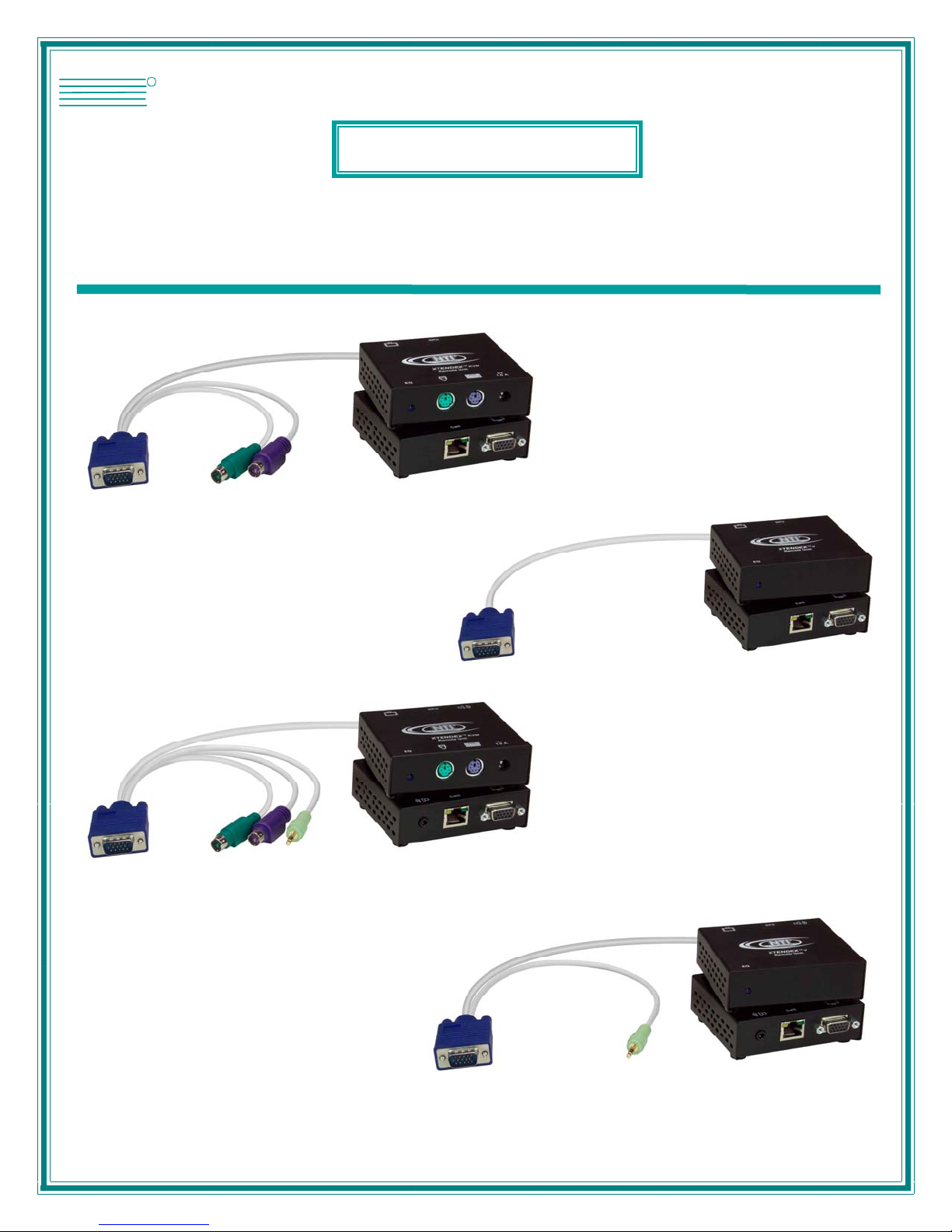
ST-C5KVM-300
PS/2 KVM Extender
ST-C5KVMA-300
PS/2 KVM and Audio
ST-C5V-300
Video Extender
ST-C5VA-300
Video and Audio
MAN074 Rev Date 4/20/2005

Warranty Information
The warranty period on this product (parts and labor) is one (1) year from the date of purchase. Please contact Network
Technologies Inc at (800) 742-8324 (800-RGB-TECH) or (330) 562-7070 or visit our website at http://www.nti1.com for
information regarding repairs and/or returns. A return authorization number is required for all repairs/returns.
COPYRIGHT
Copyright © 2005 by Network Technologies Inc. All rights reserved. No part of this publication may be reproduced, stored in a
retrieval system, or transmitted, in any form or by any means, electronic, mechanical, photocopying, recording, or otherwise,
without the prior written consent of Network Technologies Inc, 1275 Danner Drive, Aurora, Ohio 44202.
CHANGES
The material in this guide is for information only and is subject to change without notice. Network Technologies Inc reserves the
right to make changes in the product design without reservation and without notification to its users.
Trademark---- EXTENDEX is a trademark of Network Technologies Inc in the U.S. and other countries.
MAN074 Rev Date 4/20/2005

TABLE OF CONTENTS
Introduction......................................................................................................................................................................1
Materials..........................................................................................................................................................................1
Features and Functions...................................................................................................................................................2
Limitations .......................................................................................................................................................................3
Preparation for Installation ..............................................................................................................................................4
Installation .......................................................................................................................................................................5
Installing The Remote Unit ..........................................................................................................................................5
Connect the CAT5 cable..............................................................................................................................................6
Installing The Local Unit ..............................................................................................................................................7
Connect The CAT5 Cable............................................................................................................................................9
Plug-in and Boot Up.....................................................................................................................................................9
Video Quality Adjustment..............................................................................................................................................10
Technical Specifications................................................................................................................................................11
Interconnection Cable Wiring Method...........................................................................................................................12
Troubleshooting.............................................................................................................................................................12
TABLE OF FIGURES
Figure 1- Connect the Extended Components to the Remote Unit....................................................................................................5
Figure 2- Connect speakers to the Remote Unit................................................................................................................................6
Figure 3- Connect the CAT5 cable to the Remote Unit......................................................................................................................6
Figure 4- Connect the local user to the XTENDEX Local Unit...........................................................................................................7
Figure 5- Connect speakers to Local Unit with audio support............................................................................................................7
Figure 6- Connect the Local Unit with VGA video and audio support to the CPU..............................................................................8
Figure 7- Connect CAT5 cable to Local Unit......................................................................................................................................9
Figure 8- Connect the AC adapter to the Local Unit ..........................................................................................................................9
Figure 9- Connect the AC adapter to the Remote Unit ....................................................................................................................10
Figure 10- Turn "EQ" screw for video quality adjustment.................................................................................................................10
Figure 11- View looking into RJ45 female........................................................................................................................................12
MAN074 Rev Date 4/20/2005
NTI EXTENDEX Extenders
INTRODUCTION
The XTENDEX Series CAT5 Extender (XTENDEX) is designed to enable one CPU to be controlled by two users, one local and
one remote. The remote user can be located as much as 300 feet away from a PS/2 CPU via Category 5 unshielded twistedpair cable. The local user will be located near the CPU.
The XTENDEX Series Extender is extremely simple to install and has been thoroughly tested to insure reliable performance.
Through the use of Category 5 cable it is possible to economically increase the flexibility of a computer system. Here are some of
the features and ways this can benefit any workplace:
• Allows the placement of computer peripherals (monitor, keyboard, and mouse) in a location where
only these parts are needed without having the CPU there too, taking up valuable space
• Allows a PS/2 CPU to be accessed b y both a local and remote user (up to 300 feet away)
• Compatible with VGA and XGA systems
• Provides crisp and cle ar resolu tion up to 1280 x 1024 @ 300 feet (see page 11 for more details)
• Compatible with all NTI switches and splitters, enabling the joining of products to create a system that
satisfies all networking needs
• Video quality, for varying lengths of cable, is manually adjustable ( see page 10) providing optimum image
quality
• Audio frequency response is 20Hz to 20Khz, + 1dB (models with audio support only)
• Digital transmission of audio signals reduces any loss in quality (models with audio support onl y)
This manual covers each of the XTENDEX Series CAT5-300 Extender models offered. Some feat ures described in this manual
are available in some models and not in others. The chart below shows the features supported in each:
Model Video Keyboard Mouse
Support
ST-C5KVM-300
ST-C5KVMA-300
ST-C5V-300
ST-C5VA-300
VGA Yes No
VGA Yes Yes
VGA No No
VGA No Yes
Audio
Support
MATERIALS
Materials Included with this kit:
9 NTI XTENDEX Local Unit
9 NTI XTENDEX Remote Unit
9 120VAC or 240VAC at 50 or 60Hz-9VDC/1.0A AC Adapters (KVM/KVMA models include 2, V/VA models include 1)
9 This owner's manual
Additional materials may need to be ordered, depending upon the configuration:
¾ CAT5/5e/6 unshielded twisted-pair cable(s) terminated with RJ45 connectors wired straight thru- pin 1 to pin 1, etc. (see pg.
12 for proper EIA/TIA 568 B wiring method)
¾ Cable(s) needed if Local Unit will be located further than 15" from the CPU
Model Cable(s) needed
ST-C5KVM-300 VKMEXT-xx
ST-C5KVMA-300 VKMEXT-xx and SA-xx-MF
ST-C5V-300 VEXT-xx
ST-C5VA-300 VEXT-xx and SA-xx-MF
Contact your nearest NTI distributor or NTI directly for all of your KVM needs at 800-RGB-TECH (800-742-8324) in US & Canada
or 330-562-7070 (Worldwide) or at our website at http://www.nti1.com and we will be happy to be of assistance.
1
NTI EXTENDEX Extenders
6
7
1 5
N T I
N e t w o r k T e c h n o lo g i e s I n c
X T E N D E X
R
+
-
2
5
1
4
X T E N D E X
N e t w o r k T e c h n o lo g i e s I n c
N T I
R
3
( F r o n t V i e w ) ( R e a r V i e w )
9
1 0
8
1 1
1 5
N T I
N e t w o r k T e c h n o lo g i e s I n c
X T E N D E X
S T - C 5 K V M A - 3 0 0 L o c a l U n i t
R
+
-
2
5
4
X T E N D E X
N e t w o r k T e c h n o lo g i e s I n c
N T I
R
1
3
( F r o n t V i e w ) ( R e a r V i e w )
1 1
8
S T - C 5 V A - 3 0 0 L o c a l U n i t
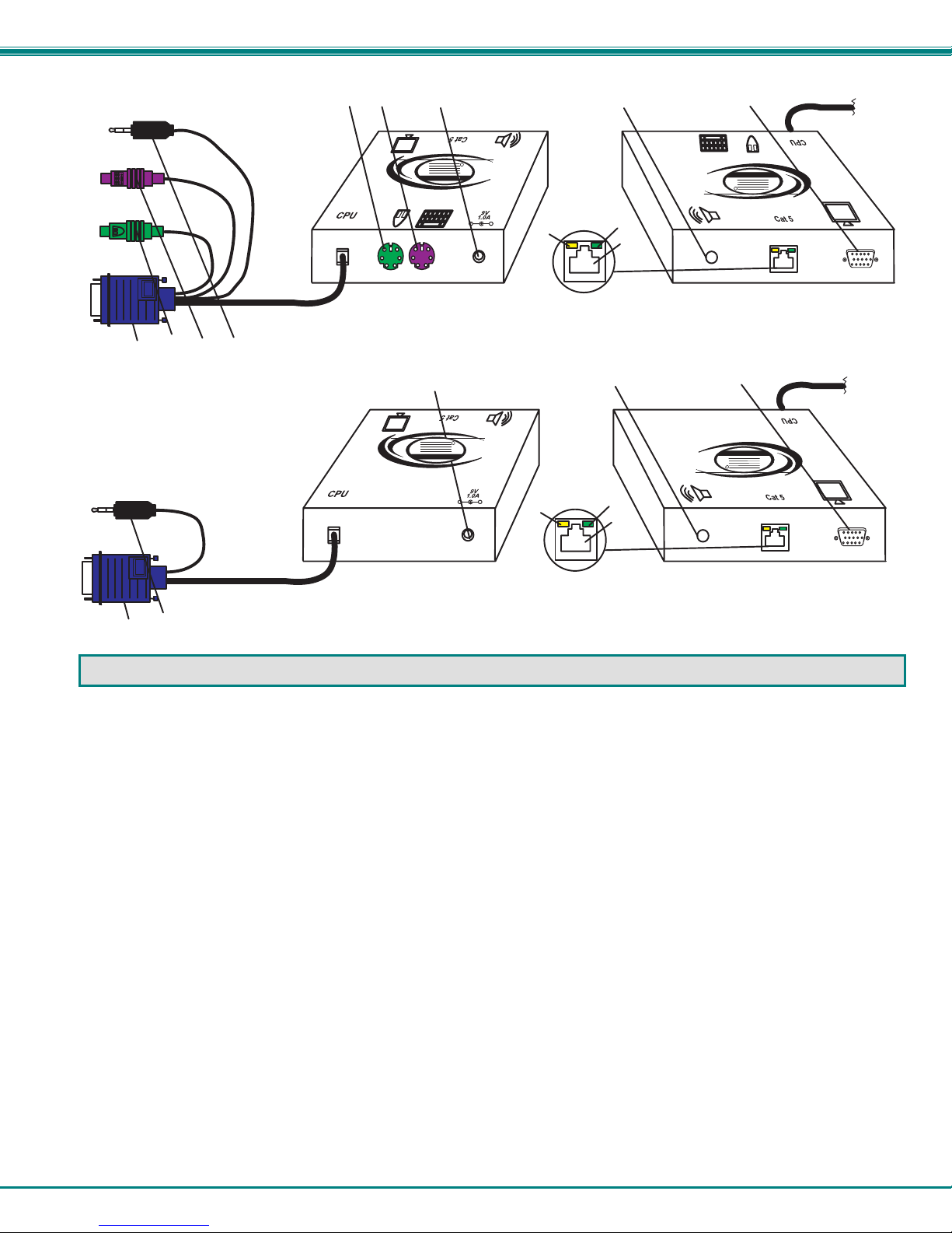
FEA TURES AND FUNCTIONS
1. Green LED- power indicator- illuminates when.power has been supplied to the unit
2. Yellow LED- traffic indicator- illuminates when there is communication between the local and remote units
3. Cat 5- RJ45 female- for connecting the CAT 5 cable
4. Video Connector- 15HD female- for connecting the local user's VGA monitor
5. Audio Jack- 3.5mm stereo audio jack- for connecting to local speakers (models with audio support only)
6. Keyboard Connector- purple female 6 miniDIN- for connecting the local user's keyboard
7. Mouse Connector- green female 6 miniDIN- for connecting the local user's mouse
8. Video Connector- blue 15HD male- for connecting to the video port on the CPU or KVM switch
9. Mouse Connector- green male 6 miniDIN- for connecting to the mouse port on the CPU or KVM switch
10. Keyboard Connector- purple male 6 miniDIN- for connecting to the keyboard port on the CPU or KVM switch
11. Audio Plug- 3.5mm stereo audio plug- for connecting to CPU audio line out (models with audio support only)
12. Keyboard Connector- purple female 6 miniDIN- for connecting the remote user's keyboard
13. Mouse Connector- green female 6 miniDIN- for connecting the remote user's mouse
14. Audio Jack- 3.5mm stereo audio jack- for connecting to remote speakers (models with audio support only)
15. 9VDC- 1.0A- connection jack for the AC adapter
2
 Loading...