

NTI XTENDEX ST-C5USBV-1000S, XTENDEX ST-C5USBVA-1000S, XTENDEX ST-C5USBVU-1000S, XTENDEX ST-C5USBVUA-1000S Installation And Operation Manual
Page 1
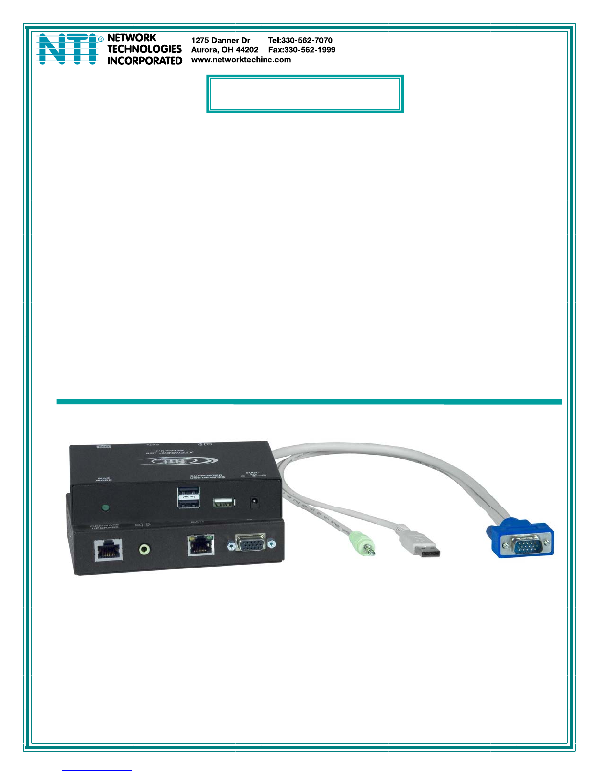
XTENDEX®Series
ST-C5USBV-1000S
ST-C5USBVA-1000S
ST-C5USBVU-1000S
ST-C5USBVUA-1000S
HI-RES VGA USB KVM EXTENDERS
With Optional Audio Support and Additional USB Port
for CAC Card Reader, Touch Screen Monitor, and
SMART Board™ Interactive Whiteboard
Installation and Operation Manual
ST-C5USBVUA-1000S
Remote and Local Units
MAN063 Rev 6/20/11
Page 2

TRADEMARK
XTENDEX is a trademark of Network Technologies Inc in the U.S. and other countries.
COPYRIGHT
Copyright © 2010, 2011 by Network Technologies Inc, all rights reserved. No part of this publication may be reproduced, stored in
a retrieval system, or transmitted, in any form or by any means, electronic, mechanical, photocopying, recording, or otherwise,
without the prior written consent of Network Technologies Inc, 1275 Danner Drive, Aurora, Ohio 44202. For more information
please contact Network Technologies Inc at (800) 742-8324 (800-RGB-TECH) or (330) 562-7070.
CHANGES
The material in this guide is for information onl y and is subject to cha nge without notice. Network Technologies I nc reserves the
right to make changes in the product design without reservation and without notification to its users.
Current Firmware Versions
Local Controller Version 1.4
Local Port Controller Version 1.4
Remote Controller Version 1.5.
Note: CAT5 connection cable used between NTI XTENDEX Series Local and Remote or any XTENDEX Series products
should not be run underground, outdoors or between buildings.
!
WARNING: Outdoor or underground runs of CAT5 cable could be dangerous and will void the warranty.
i
Page 3

Table of Contents
Introduction....................................................................................................................................................................1
Types of User Input Devices Supported......................................................................................................................1
Operating Systems Supported ....................................................................................................................................2
Limitations....................................................................................................................................................................2
Materials.........................................................................................................................................................................2
Features and Functions................................................................................................................................................3
Preparation for Installation...........................................................................................................................................4
Installation......................................................................................................................................................................5
The Local Unit..............................................................................................................................................................5
Connect to the CPU..................................................................................................................................................5
Connect the Local Devices.......................................................................................................................................6
The Remote Unit..........................................................................................................................................................7
Connect the CAT5 Cable.............................................................................................................................................8
Plug-in and Boot Up.....................................................................................................................................................9
Configuration and Command Mode..........................................................................................................................10
Command Mode........................................................................................................................................................10
Adjust Brightness....................................................................................................................................................10
Automatic Video Quality Adjustment......................................................................................................................10
Fine Video Quality Adjustment ...............................................................................................................................11
General Video Quality Adjustment......................................................................................................................11
Color Skew Adjustment.......................................................................................................................................11
Test Patterns .......................................................................................................................................................11
Update DDC............................................................................................................................................................11
Toggle MAC Mode..................................................................................................................................................12
Exit Command Mode ..............................................................................................................................................12
Common Applications................................................................................................................................................13
Firmware Upgrade Procedure....................................................................................................................................14
Requirements ............................................................................................................................................................14
Prepare to Upgrade the Firmware.............................................................................................................................15
Upgrade Procedures..................................................................................................................................................16
Start the Bootloader................................................................................................................................................16
Upgrade the Local Controller Firmware..................................................................................................................16
Upgrade the Local Port Controller Firmware..........................................................................................................17
Upgrade the Remote Controller Firmware..............................................................................................................17
Technical Specifications ............................................................................................................................................19
Interconnection Cable Wiring Method ......................................................................................................................20
Keyboard Translation .................................................................................................................................................20
Key Equivalents.........................................................................................................................................................20
SUN’s 16 Extra Keys.................................................................................................................................................21
Troubleshooting..........................................................................................................................................................23
Index.............................................................................................................................................................................24
Warranty Information..................................................................................................................................................24
Table of Figures
Figure 1- Connect the Local Unit to a CPU........................................................................................................................................5
Figure 2- Connect local user devices to the Local Unit......................................................................................................................6
Figure 3- Connect the Monitor and Devices to the Remote Unit........................................................................................................7
Figure 4- Connect the CAT5 cable to the Local Unit..........................................................................................................................8
Figure 5- Connect AC adapter to Remote Unit..................................................................................................................................9
Figure 6- MAC Mode LED................................................................................................................................................................12
Figure 7- Examples of common applications...................................................................................................................................13
Figure 8- Connect PC for firmware upgrade....................................................................................................................................15
Figure 9- Pin positions in female RJ45 connector............................................................................................................................20
Figure 10- Keyboard Layouts...........................................................................................................................................................22
ii
Page 4
INTRODUCTION
The ST-C5USBV-1000S HI-RES VGA USB KVM Extender (XTENDEX) is designed to enable the relocation of a monitor, USB
keyboard, and USB mouse from a USB CPU or NTI USB KVM switch by as much as 1000 feet via CAT5/5e/6 cable. The option
to extend stereo audio speakers, USB touch screen monitor, CAC card reader, or SMART Board is also available. Additionally,
all extended components can be connected locally. It is extremely simple to instal l and has been thoroughly tested to insure
reliable performance. Through the use of Category 5/5e/6 shielded or unshielded twisted-pair cable (STP/UTP) it is possible to
economically increase the flexibility of a computer system.
Features
• Allows the placement of a monitor, USB keyboard, and USB mouse in a location where only these parts are needed
without having the CPU there too, taking up valuable space and adding to room noise.
• Provides crisp and clear resolution up to 1920 x 1200 /60Hz @ 1000 feet (see chart on page 19)
• Industry-leading ultra-high resolutions up to 2048x1536
• Video quality adjustment is automatic providing optimum image quality for varying lengths of cable. Manual fine
adjustments are made via keyboard commands.
• Installation can be between a CPU and devices (keyboard, mouse, and monitor), between a CPU and NTI USB switch,
or between a NTI USB switch and devices.
• Allows hot-plugging of keyboards and mice
• DDC2B support for local or remote monitor (user selectable)
• Available with optional stereo audio and/or additional USB port for remote and local user.
• For the additional USB port on the local unit, connect any type of USB device (fully transparent USB connection)
• For the additional USB port on the remote unit, use to connect a USB touch screen monitor, CAC
card reader, or SMART Board™ Interactive Whiteboard
• Firmware is field upgradeable via serial port (models with additional USB support only)
• USB ports support USB 2.0 (low/full speed) devices
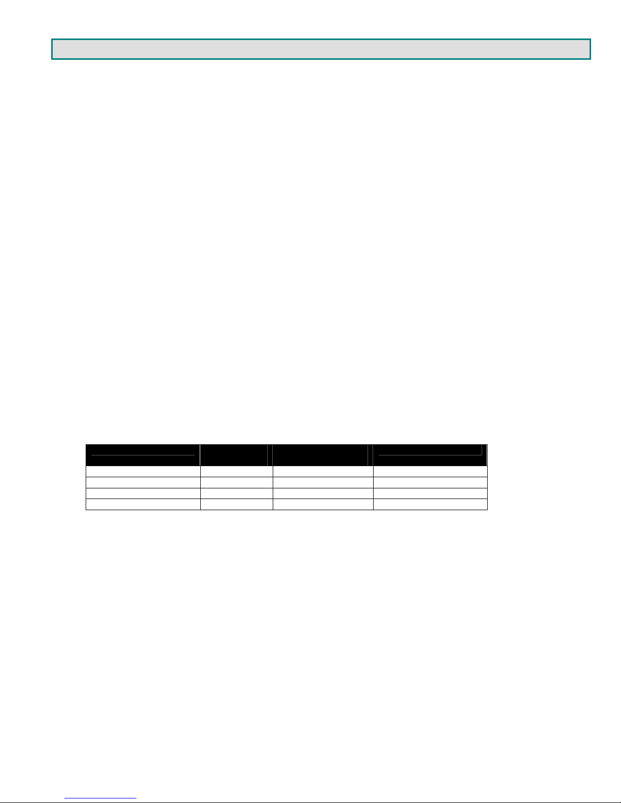
Models Available:
MODEL AUDIO
ST-C5USBV-1000S N N N
ST-C5USBVA-1000S Y N N
ST-C5USBVU-1000S N Y Y
ST-C5USBVUA-1000S Y Y Y
SUPPORT
ADDITIONAL USB
SUPPORT
FIELD UPGRADEABLE
Types of User Input Devices Supported
• XGA, VGA, and SVGA systems
• All NTI USB switches
• Microsoft, Logitech or Kensington Wheelmouse or Trackball on MAC CPUs with manufacturer's drivers
• USB keyboard with Windo ws® layout
• USB keyboard with SUN layout
• USB keyboard with MAC layout
• USB Mouse - (up to 3 buttons)
• USB IntelliMouse
• Logitech Cordless Elite Duo keyboard and mouse
• Crystal Vision keyboard with touchpad
• Gyration keyboard and mouse
• NTI USB-PS/2 Adapter
• NTI USB-SUN Adapter
• USB touch screen monitor (models with additional USB support only)
• SMART Board™ Interactive Whiteboard (models with additional USB support only)
• USB CAC card reader (models with additional USB support only)
• NEC Multisync E222W (firmware version 1.5 and later)
• Motorola Symbol LS3408 Bar Code Scanner (firmware version 1.3 and later)
•
Smart Podium monitors (tested with ID422W and ID370) (firmware version 1.3 and later)
®
(scrollwheel)
1
Page 5

Operating Systems Supported
• Windows 95,98 • Windows 2000 • Windows ME
• Window XP • Windows Vista • Windows 7
• Linux 7.1 or greater • Sun-Solaris • MAC OS 9.1 or greater
Limitations
• PS/2 devices can be connected to the XTENDEX through an NTI USB-PS/2 adapter, however the translation keys described
on page 12 will not function in this application.
• The XTENDEX can be used between a cascadable NTI switch and a CPU although the cascading features will not function.
MATERIALS
Materials supplied with this kit:
9 NTI XTENDEX Local Unit
9 NTI XTENDEX Remote Unit
9 2-120VAC or 240VAC 50 or 60Hz-5VDC/3A AC Adapters
9 CD with a pdf file of this owner's manual
Models with additional USB support (ST-C5USBVU/C5USBVUA-1000S) also include:
9 1- DB9 Female-to-RJ45 Female adapter
9 1- 5 foot RJ45-to-RJ45 CAT5 patch cable
Additional materials may need to be ordered, depending upon the configuration :
¾ USBVEXT-3/6/10 (15HD Male-to-Female and USB Type A Male-to-Female Extension cable) if the Local Unit will be located
further than 15" from the CPU or KVM switch
¾ CAT5/5e/6 shielded/unshielded twisted-pair cable(s) terminated with RJ45 connectors wired straight thru- pin 1 to pin 1, etc.
(see pg. 13 for proper EIA/TIA 568B wiring method)
Contact your nearest NTI distributor or NTI directly for all of your KVM needs at 800-742-8324 (800-RGB-TECH) in US & Canada
or 330-562-7070 (Worldwide) or at our website at http://www.networktechinc.com and we will be happy to be of assistance.
2
Page 6
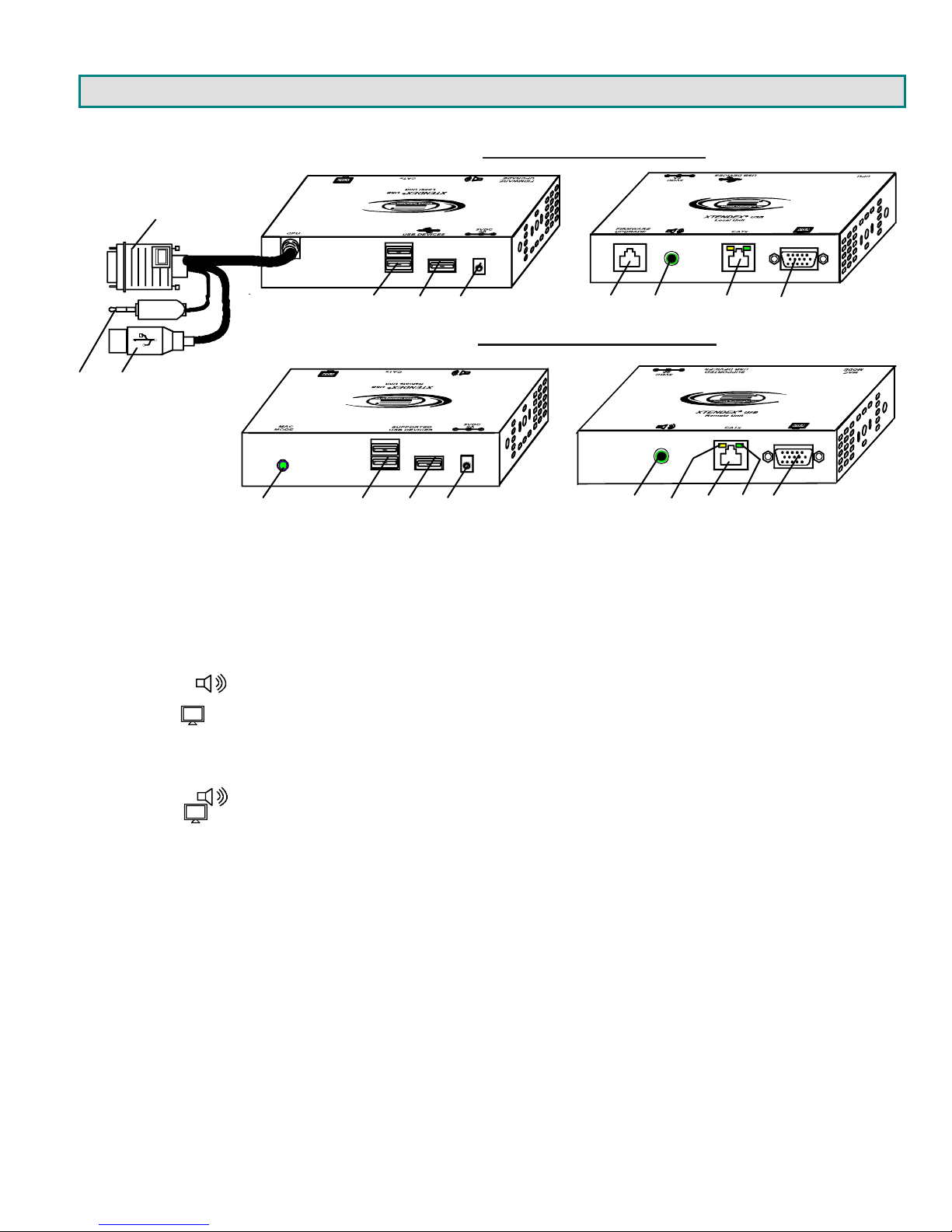
FEA TURES AND FUNCTIONS
23
1. Video Cable- 15HD male for connection to video connector of CPU
2. Audio Cable- 3.5mm plug- for connection to audio connector of CPU
3. Devices Cable- USB Type A male connector for connection to CPU
4. USB DEVICES- USB Type A female for connection of local user USB device(s)
5. USB DEVICE- USB Type A female for local connection of additional USB device (any)
6. 5VDC- connection jack for Local Unit AC adapter
7. RS232 Control - for connection of terminal to update program (models with Additional USB Support only)
8. Audio Out ( )- 3.5mm Stereo Jack- for local connection of self-powered stereo speakers
9. CATx- RJ45 female for connection of CAT5/5e/6 cable between Local Unit and Remote Unit
10. Monitor ( )- 15HD female for connection of video cable from local monitor
11. MAC LED- for visual indication that the Local Unit is configured for connection to a MAC CPU
12. USB DEVICES- USB type A female for connection of remote user USB device(s)
13. USB DEVICE- USB Type A female for remote connection touch screen, CAC reader, or SMART Board™ only
14. 5VDC- connection jack for Remote Unit AC adapter
15. Audio Out ( )- 3.5mm Stereo Jack- for remote connection of self-powered stereo speakers
16. Monitor ( )- 15HD female for connection of video cable from remote monitor
17. Yellow LED- traffic indicator- blinks when there is valid communication between the Local and Remote Units.
18. Green LED- power indicator- illuminates when power has been supplied to the unit
1
11 12 13 14
VGA
VGA
Rear View
456 78 910
Rear View
ST-C5USBVUA-1000S Local Unit
ST-C5USBVUA-1000S Remote Unit
17
15
916
Front View
Front View
18
3
Page 7

PREPARATION FOR INSTALLATION
• A location should be chosen for the monitor, mouse, and keyboard that also has space to mount the Remote Unit within the
distance provided by the cables from the monitor, mouse, and keyboard. If extension cables are needed, contact NTI for the
cables required. If a local user will be connected, a proper location must be chosen for these devices too.
• The CAT5 cable(s) must be run to the locations where the Remote and Local Units will be placed. Be careful to route the
cables away from any sources of magnetic fields or electrical interference that might reduce the quality of the video signal
(i.e. AC motors, welding equipment, etc.). NOTE: If CAT5 cable is already installed in the wall and there are RJ45 wall
outlets, it will be necessary to obtain male-to-male straight through connection cables long enough to reach from the wall
outlets to the mounting locations of the Remote and Local Units.
• A properly grounded, polarized, and preferably surge-protected 120V or 240V electrical outlet (de pending on the AC adapter
being used) must be installed close enough to the mounting location of the Remote Unit and monitor to plug them into.
• All cables should be installed in a fashion that will avoid stress on their connections to the equipment. Extended lengths of
cable hanging from a connection may interfere with the quality of that connection. Secure cables as ne eded to prevent this.
• Properly shut down and disconnect the power of the CPU and monitor. Disconnect the monitor, keyboard, and mouse. If
other equipment is involved whose connections are being interrupted, be sure to refer to the instruction manuals for that
equipment for proper disconnection and re-connection procedures before proce eding.
Note: CAT5 connection cable used between NTI XTENDEX Series Local and Remote or any XTENDEX Series products
should not be run underground, outdoors or between buildings.
!
WARNING: Outdoor or underground runs of CAT5 cable could be dangerous and will void the warranty.
4
Page 8
INSTALLATION
The Local Unit
Connect to the CPU
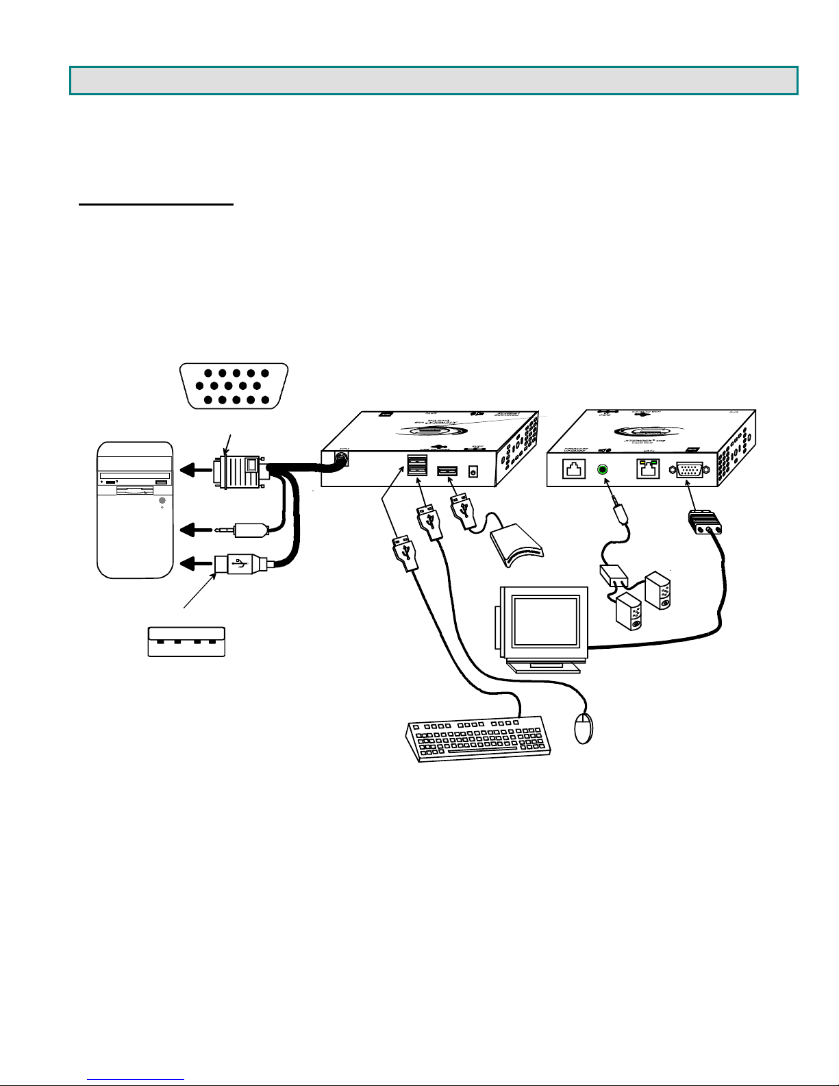
1. Plug the cables of the Local Unit into the back of the CPU. (See Fig. 1.)
a) Connect the blue 15HD cable from the Local Unit to the female VGA port on the back of
the CPU.
b) Connect the USB Type A cable from the Local Unit to a female USB Type A port on the back of the CPU.
c) If the extender model incl udes audio support, connect the 3.5mm stereo plug to the audio port on the back of
the CPU.
Video Connector
15HD Male
Rear View Front View
B
U
S
P
U
C
3.5mm Stereo Plug
USB-A - Male
USB-A - Male
USB Type A male
Figure 1- Connect the Local Unit to a CPU
ST-C5USBVUA-1000S Local Unit
3.5mm
Stereo Plug
CAC
Reader
VGA
Multi-Scan
Monitor
USB Mouse
USB Keyboard
Self-Powered
Amplifier
Stereo
Speakers
15HD Male
Video
Connector
5
Page 9
Connect the Local Devices
If desired, connect the local user devices to the Local Unit as shown in Fig. 2.
1. Connect a USB keyboard and mouse to the USB type A female connectors on the Local Unit.
2. Connect a monitor to the 15HD female connector on the Local Unit.
3. If the unit has audio support, connect self-powere d stereo speakers to the audio out port ( ) on the Local
Unit.
4. If the unit has additional USB support, connect any USB device (supports USB 2.0 (low/full speed)) to the
additional USB type A female connector on the Local Unit.
USB Type A male
Figure 2- Connect local user devices to the Local Unit
Rear View Front View
ST-C5USBVUA-1000S Local Unit
3.5mm
Stereo Plug
CAC
Reader
VGA
Multi-Scan
Monitor
USB Mouse
USB Keyboard
Self-Powered
Amplifier
Stereo
Speakers
15HD Male
Video Connector
6
Page 10

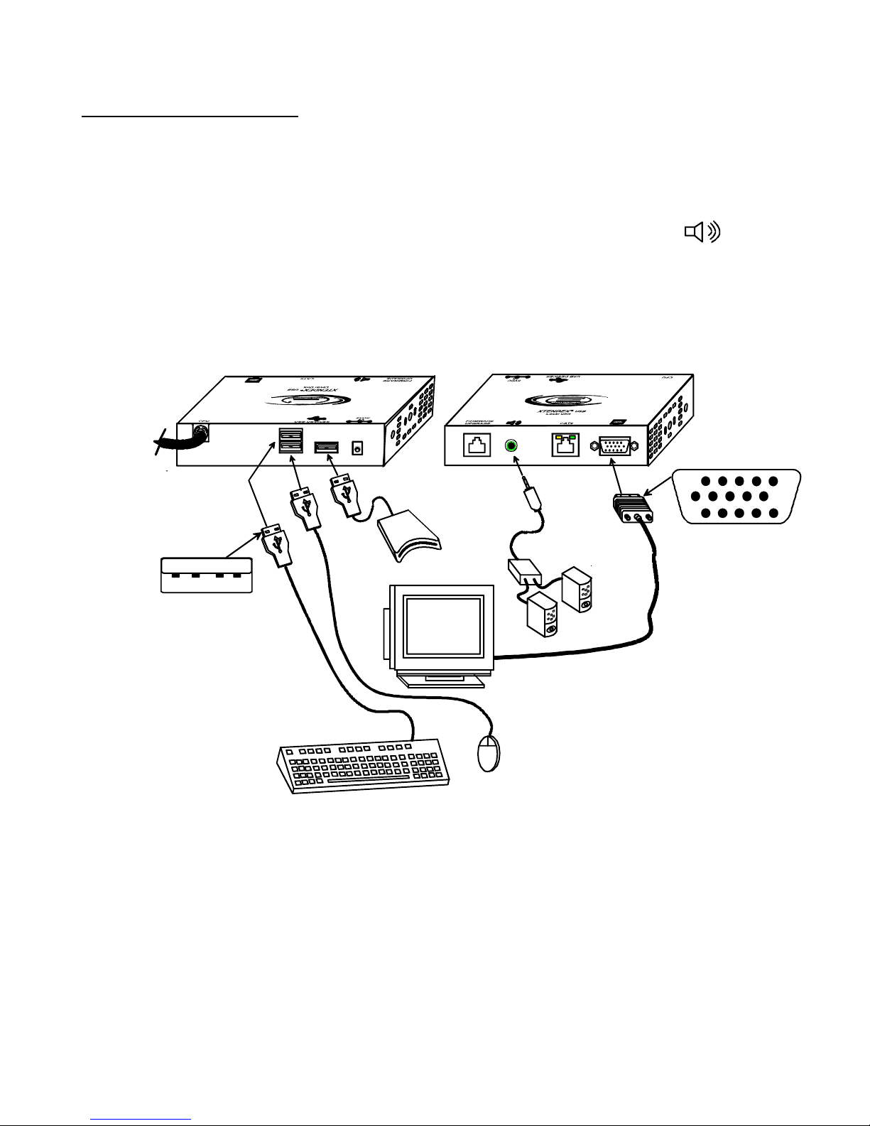
The Remote Unit
Position the Remote Unit such that each cable to be connected to it can reach the Remote Unit comfortably.
1. Connect a USB keyboard and mouse to the USB type A female connectors on the Remote Unit.
2. Connect the monitor cable to the 15H D female connector on the back of the Remote Unit. (See Fig. 3)
3. If the unit has audio support, connect self-powered stereo speakers to the audio out port ( ) on the Remote
Unit.
4. If the unit has additional USB support, connect a CAC card reader, SMART Board™, or the USB serial connector
from a touch screen monitor to the additional USB type A female connector on the Local Unit.
Rear View Front View
USB Type A male
Figure 3- Connect the Monitor and Devices to the Remote Unit
ST-C5USBVUA-1000S Remote Unit
3.5mm
Stereo Plug
CAC
Reader
VGA
Multi-Scan
Monitor
USB Mouse
USB Keyboard
Self-Powered
Amplifier
Stereo
Speakers
15HD Male
Video Connector
7
Page 11

Connect the CAT5 Cable
Make sure the CAT5/5e/6 cable has been installed in accordance with the “Preparation for Installation” instructions on page 4.
Connect one end of CAT5 cable to the “CATx” port on the back of the Remote Unit, and the other end to the “CATx” port on the
Local Unit. When properly inserted the CAT5 cable ends should snap into place.
WARNING: Never connect the ST-C5USBV-1000S Extender to an Ethernet card, Ethernet router, hub or
switch or other Ethernet RJ45 connector of an Ethernet device. Damage to devices connected to the
!
Ethernet may result.
RJ45 female
CAT5 connector
Yellow Traffic LED
Figure 4- Connect the CAT5 cable to the Local Unit
Green Powe r LED
ST-C5USBVUA-1000S Local Unit ST-C5USBVUA-1000S Remote Unit
Front Vie w
Front Vie w
RJ45 Connector RJ45 Connector
CAT5/5e/6 cable
Up to 1000 feet
8
Page 12

Plug-in and Boot Up
1. Plug the power cord from the monitor into the power outlet.
2. Connect one AC adapter power connector to the 5VDC port on the back of the Local Unit. (AC adapter shown in Fig. 5)
3. Plug the AC adapter into a power outlet. The green “Power” LED on the Local Unit should illuminate, indicating that a proper
power connection has been made to the Local Unit.
4. Connect the other AC adapter power connector to the 5VDC port on the Remote Unit.
5. Plug the AC adapter into a power outlet. The green “Power” LED on the Remote Unit should illuminate, indicating that a
proper power connection has been made to the Remote Unit.
6. Turn ON the monitor, then the CPU. The CPU and monitor should each react as if they were directly connected to each
other. The yellow traffic LEDs on the Remote and Local Units (see fig. 3) should blink indicating there is proper
communication between them.
Note: A loss of signal (blank screen) may be experienced for an instant during the auto-co mp en sation process after
powering-up. This may also occur if the XTENDEX senses a loss of or weak signal connection in the CAT5 cable.
Figure 5- Connect AC adapter to Remote Unit
5 VDC
Adapter
ADAPTER
Barrel
Power Connector
5VDC @ 3A OUTPUT (Requires 2A minimu m)
(Outside
barrel)
2.1 mm x 5.5 mm Female
ST-C5USBVUA-1000S Remote Unit
Rear View
(Inside
barrel)
9
Page 13

CONFIGURATION AND COMMAND MODE
Command Mode
All models are enabled with a Command Mode feature to perform the following:
Command Mode can be enabled by two keys at the same time; <LEFT SHIFT> + <RIGHT SHIFT>. Press <Esc> at any time
to exit Command Mode.
The three keyboard LEDs (NumLock, CapsLock, and ScrollLock) will blink at the same time to indicate entrance into Command
Mode.
Commands available in Command Mode:
Key press Effect Extra Control
<Up Arrow>
<Down Arrow>
<A>
<Left Arrow>
<Right Arrow>
<R>
<G>
<B>
<D>
<V>
<M>
<W>
<Esc>
¾ fine adjustment of the general video quality
¾ fine adjustment of color skew (alignment of red, green, and blue signals on the monitor)
¾ update DDC information between the monitor(s) and CPU
¾ toggle between MAC mode and non-MAC mode
increases brightness
decreases brightness
forces Auto Video Quality
Adjustment
Decreases fine video adjustment
Increases fine video adjustment
Enable Red
Mode
Enable Green
Adjustment Mode
Enable Blue
Mode
DDC Update Mode
Returns to General Video Quality
Adjustment Mode from DDC Update
Mode or Color Skew Adjustment
Modes
Enable MAC Mode
Disable MAC Mode
Exits Command Mode
Color Skew Adjustment
Color Skew
Color Skew Adjustment
Use <Left Arrow> or <Right
Arrow> to adjust
Use <Left Arrow> or <Right
Arrow> to adjust
Use <Left Arrow> or <Right
Arrow> to adjust
Adjust Brightness
The brightness of the extended image can be increased or decreased by pressing the <Up Arrow> or <Down Arrow>
(respectively) while in Command Mode. This adjustment is in addition to any adjustments made possible by controls on your
monitor.
Automatic Video Quality Adjustment
Video quality is broken down into “general video quality” for brightness and sharpness of the images, and “color skew” for how the
colors align with each other on the monitor. Both general video quality and color skew adjustments are done automatically any
time the XTENDEX is powered ON or if the CATx cable is disconnected and then reconnected. T hese adjustments can also be
forced by pressing the <A> key while in Command Mode.
The automatic video adjustments are calibrated for unshielded twisted pair cable. For shielded cable fine adjustment may be
necessary and this can be done from keyboard keys using Command Mode. Video Quality Adjustment settings are automatically
stored in the XTENDEX. Settings will be restored each time the XTENDEX is powered-ON. Test patterns for color skew
adjustment are provided on the CD.
Note: If the cable is changed after making manual video adjustments, the XTENDEX will restore these settings to factory
default and fine adjustments with the new cable may be necessary.
10
Page 14

Fine Video Quality Adjustment
General Video Quality Adjustment
Command Mode opens into General Video Quality Adjustment mode. To fine tune the general video qualit y, press the <Left
Arrow> or <Right Arrow> keys until the desired improvement in the display has been achieved.
Color Skew Adjustment
If a specific color appears to be skewed and is in need of fine adjustment, the user can switch to Red, Green, or Blue Skew
Adjustment mode by pressing <R>, <G> or <B> respectively. The keyboard LEDs will identify the mode as indicated in the table
below. Press the < Left Arrow> or <Right Arrow> keys until the desired improvement in the color alignment has been
achieved. Press <V> to return to General Video Quality Adjustment mode.
Test Patterns
To verify the need for and effect of color skew adjustment using a test pattern specifically designed for your display setting,
browse the CD this manual was found on and click on the “test-pattern-nXm.pdf” file that matches your current video resolution.
Follow the instructions above to make adjustments as needed.
Note: For additional quality adjustment, it may be necessary to adjust the brightness and con trast settings of the
monitor.
Keyboard LEDs Indications:
Adjustment Mode NumLock CapsLock ScrollLock
Command Mode ON Blink Blink Blink
Red Skew Blink Solid Solid
Green Skew Solid Blink Solid
Blue Skew Solid Solid Blink
DDC Update Off Solid Off
Command Mode OFF Normal state Normal state Normal state
Update DDC
DDC information allows the CPU to automatically select the optimal resolution for your monitor. The procedure to u pdate DDC
information (below) must be performed only once at initial setup through Command Mode (provided the monitor is not changed).
Both the Local and Remote Units must be powered in order to update the DDC information. The DDC information will be based
on the monitor connected to the Remote Unit.
To update DDC information (from Command Mode);
1. press <D> to enter DDC Update mode. (See chart above for LED indications.)
2. press the < Left Arrow> + <Right Arrow> keys simultaneously to cause DDC information to be updated
When the update is complete (less than one second), the three keyboard LEDs will blink at the same time.
3. press <V> to return to General Video Quality Adjustment mode.
4. press <Esc> to exit Command Mode
5. Restart the CPU.
Note: It is recommended that the monitors connected to the Remote and Local units be of the same make and model.
Attention: Some graphics cards will not send a video signal to the monitor until it has received the DDC information from the
monitor. In this case, the monitor may not display anything until the DDC information is read. This may occur if this is the first
time the monitor is being connected to the XTENDEX. The DDC information must be updated in the XTENDEX to achieve video
using the procedure outlined above.
If the monitor is changed to a different model than was initially installed, the update procedure must be repeated through
Command Mode.
11
Page 15

Toggle MAC Mode
MAC Mode enables the user to connect the Local Unit to a MAC CPU. MAC Mode configures the Local Unit for passing mouse
information to the MAC CPU. This is useful when the user wants to use mouse drivers provided by the mouse vendor, which
allows the use of programmable functions for each mouse button. The Local Unit can be configured whenever n ecessary.
In the default setting (non-MAC Mode), the XTENDEX is configured for connection to a SUN or Windo ws CPU. To toggle
between non-MAC Mode and MAC Mode, press <M> while in Command Mode. The “MAC Mode” LED on the Remote Unit will
illuminate when the XTENDEX is in MAC Mode.
NOTE: When the port is connected to a PC or SUN CPU, MAC Mode (and the MAC Mode LED) should be OFF.
To do this;
1. Enter Command Mode. (Simultaneousl y pr ess the left and right <Shift> keys on the keyboard connected to the Remote
Unit. The keyboard LEDs will illuminate. )
2. If a MAC CPU is connected, press the <M> key. The keyboard LEDs will momentarily flash and the “MAC” LED on the
Remote Unit will illuminate to indicate MAC Mode is ON. (See Error! Reference source not found.)
To reconnect the XTENDEX to a SUN or Windows CPU (the default setting) , press the <W> key and the “MAC” LED will go OFF.
Figure 6- MAC Mode LED
MAC por t configu r ation LE D
ST-C5USBVUA-1000S Remote Unit
Rear View
Exit Command Mode
Press the <Esc> key to exit Command Mode and return to normal operation. All keyboard LEDs will return to current keyboard
LED state.
FYI: Video quality will be limited by several factors. Some factors include the quality and type of CAT5 cable being
used, the length of cable run, the quality of the monitor, the resolution setting of the monitor, and the quality of the video
card used in the video source. If the desired level of image clarity cannot be achieved by making the adjustments
described in this section, consider the following possible adjustments that can be made:
• Improve the quality of cable used -CAT5,5e,or 6 (CAT5e unshielded (UTP) cable will provide the best
performance)
• Use unshielded cable (UTP) instead of shielded cable (STP)
• Shorten the length of the cable between the remote and local
• Reduce the resolution setting on the monitor used
• Use a higher quality video card in the video source
12
Page 16

COMMON APPLICATIONS
Figure 7 (below) illustrates three common applications for the ST-C5USBV-1000S USB KVM Extender.
VGA
Multi-Scan
Monitor
USB Mouse
USB Keyboard
Local User Local User
USB Mouse
STANDARD APPLICATION
BETWEEN USERS AND CPU
Existin g Loc a l Un it Ca b le
XTENDEX
LOCAL UNIT
CAT5 Cable
XTENDEX
REMOTE UNIT
VGA
Multi-Scan
Monitor
USB Keyboard
USB Mouse
VGA
Multi-Scan
Monitor
USB Keyboard
Existin g Loc a l Un it Ca b le
XTENDEX
LOCAL UNIT
CAT5 Cable
XTENDEX
REMOTE UNIT
USBVEXT-xx-MM
NTI USB
KVM MATRIX
SWITCH
(UNIMUX-nXm-U)
VGA
Multi-Scan
Monitor
USB Mouse
USB Keyboard
BETWEEN CPU AND
MULTI-USER MATRIX
SWITCH
USB Mouse
USBVEXT-xx-MM
Existin g Loc a l Un it Ca b le
VGA
Multi-Scan
Monitor
USB Keyboard
Local User
LOCAL UNIT
CAT5 Cable
REMOTE UNIT
BETWEEN SINGLEUSER KVM SWITCH
AND USERS
NTI USB
KVM
SWITCH
(UNIMUX-xU)
XTENDEX
XTENDEX
USB KeyboardUSB Mouse
VGA
Multi-Scan
Monitor
Figure 7- Examples of common applications
13
Page 17

FIRMWARE UPGRADE PROCEDURE
This procedure describes how to upgrade the firmware in this XTENDEX. Only models with Additional USB Support can be
upgraded. If you are not certain whether this XTENDEX has the most up-to-date firmware available, simply download the latest
version and follow the upgrade procedure. All versions of firmware can be downloaded from
http://www.networktechinc.com/usbkvm.html
The XTENDEX has 3 types of micro-controllers:
1. Local Controller – the Local Controller will be upgraded with a binary file named c5usbvu-lcsx-x.bin. (where x-x is the rev
number)
2. Local Port Controller – the Loc al Port Controller will be upgraded with a hex file named c5usbvu-lcpx-x.hex.
3. Remote Controller – the Remote Controller will be upgraded with a bin file named uc5usbvu-rcsx-x.bin.
The XTENDEX firmware has a bootloader which can be used for firmware upgrades. T he bootloader resides in a protected ar ea
of Flash memory, so that if the upgrade fails for any r eason, the bootloader will still be available to be used to r e-program the
entire unit.
Upgrades are made to the Local Controller, Loca l Port Controller, or Remote Controller separately. Not all Controller firmware is
updated with each revision, however it is highly recommended that if you upgrade one piece of firmware, you upgrade each
controller segment to make sure your Local and Remote are both at current versions.
.
Requirements
¾ CAT5 Patch Cable (supplied with XTENDEX)
¾ RJ45-DB9 or DB25 Adapter (supplied with XTENDEX)
¾ Computer with a Terminal Console (for example, HyperTerminal in Windows, or any similar program able to send files using
Xmodem protocol)
¾ Firmware files for the XTENDEX on the computer with the Terminal Console.
14
Page 18

Prepare to Upgrade the Firmware
With the power to the PC and XTENDEX OFF, connect a PC to the XTENDEX using the supplie d 5 foot patch cable and 9DB-toRJ45 adapter. Connect the patch cable to the “FIRMWARE UPGRADE” port on the Local Unit, attach the supplied 9DB-to-RJ45
adapter to the patch cable, and connect the 9DB adapter to an available COM port on the PC.
Figure 8- Connect PC for firmware upgrade
CAT5 Patch Cable
(supplied)
ST-C5USBVUA-1000S Local Unit
Front Vie w
RJ45-to-DB9 Adapter
(supplied)
Control Terminal
VGA
Multi-Scan
Monitor
2. Power ON the computer only. Open the terminal console and apply the following settings to the terminal console for the port
connected to the XTENDEX:
Baud rate: 57600
Data bits: 8
Parity: none
Stop bits: 1
Flow control: none
15
Page 19

Upgrade Procedures
Start the Bootloader
In the HyperTerminal window on the attached computer, press and hold the <Tab> key and power ON the XTENDEX.
The following message (or one similar) will be displayed on the screen:
ST-C5-USBVA Bootloader
Revision: 1.1
Date: 2010/01/11 15:40:16
Copyright (C) Network Technologies Inc.
Press <H> for help…
>
Release the <Tab> key.
The “>” prompt indicates that the bootloader is waiting for commands. The available commands are composed by sending one
ASCII character. To send a command to the bootloader, t ype the key in the terminal window that corresponds to the desired
command. The available commands, listed below, can be viewed by typing <h> or <H> (the Help command) from the keyboard.
Note: Commands can be typed using upper or lower case letters.
Local Bootloader List of Commands:
h, H - Display list of commands
x, X - Exit Bootloader
u, U - Upgrade Local controller firmware
p, P - Upgrade Local port controller firmware
r, R - Upgrade Remote controller firmware
s, S - Read Checksum of the Local port controller firmware
Upgrade the Local Controller Firmware
The Local controller firmware comes as a file in binary format and has the extension .bin. (i.e. filename.bin). T o upgrade the
Local controller to this file, press <u> from Terminal window. The following message should appear on the screen:
Erasing flash memory…
Memory successfully erased
Send .bin file using Xmodem protocol..
At this point the binary file c5usbvu-lcsx-x.bin must be sent. To do this, from HyperTerminal:
1. go to “Transfer” menu in the Menu Bar of the HyperTerminal window
2. click the item “Send File …”
3. in the dialog box which pops up on the screen, browse for the file to be sent and select it
4. select “Xmodem” from the Protocol drop-down menu
5. press “Send” button
The transmission will start shortly. Wait until the transmission is finished. There will be some pauses during transmission, since
the processor writes blocks of 4KB.
When the transmission is complete, the HyperTerminal window should show the following status message and return to the menu
prompt:
Device successfully programmed!
>
To exit from the bootloader, press <x>.
16
Page 20

Upgrade the Local Port Controller Firmware
The Local port controller firmware comes as a file in Intel Hex format and has the extension .hex (i.e. filename.hex). To upgrade
any of Local Port controller with this firmware, press <p> from the terminal window. The following message should appear on the
screen:
Send .hex file using XModem protocol...
At this point, the hex format file c5usbvu-lcpx-x.hex has to be sent, using HyperTerminal and the same procedure as before.
When the transmission is done, the following message will be shown in the HyperT erminal window:
File transfer OK!
Please, type <A> to program chip or <X> to exit
To program the chip, just press <a>).
The following message will be shown on the screen (it may take about 12 seconds to program):
Programming device, please wait...
Device ID: 0x001E
Device successfully programmed!
To exit from the bootloader, press <x>.
Note: The Local port
include both of the current Local and Remote controller firmware versions, but will only include the Local port
firmware if it has changed.
controller firmware will rarely, if ever, need to be updated. The firmware download package will
controller
Upgrade the Remote Controller Firmware
The Remote controller firmware comes as a file in binary format and has the extension .bin. (i.e. filename.bin). To upgrade the
Remote controller to this file, press <r> from Terminal window. The following message should appear on the screen:
The Local Unit bootloader will now pass control
to the Remote Unit bootloader
Please, check that the Remote Unit is powered off
Please, type <Y> to continue or <X> to cancel
If you type <Y> to continue you get the following message:
To enter into Remote Unit bootloader, power on the unit
while keeping the <TAB> key pressed
Remote Bootloader List of Commands:
h, H - Display list of commands
x, X - Exit Bootloader
r, R - Upgrade Remote controller firmware
To proceed to upgrade the Remote controller, press <r> from Terminal window. The following message should appear on the
screen:
Erasing flash memory…
Memory successfully erased
Send .bin file using Xmodem protocol..
17
Page 21

At this point the binary file c5usbvu-rcsx-x.bin must be sent. To do this, from HyperTerminal:
1. go to “Transfer” menu in the Menu Bar of the HyperTerminal window
2. click the item “Send File …”
3. in the dialog box which pops up on the screen, browse for the file to be sent and select it
4. select “Xmodem” from the Protocol drop-down menu
5. press “Send” button
The transmission will start shortly. Wait until the transmission is finished. There will be some pauses during transmission, since
the processor writes blocks of 4KB.
When the transmission is complete, the HyperTerminal window should show the following status message and return to the menu
prompt:
Device successfully programmed!
>
To exit from the bootloader, press <x>.
18
Page 22

TECHNICAL SPECIFICATIONS
Video Compatibility SVGA, XGA, VGA
Video Quality Variable for up to 1000 feet of CAT5 cable
Video Coupling DC
Video Connectors HD15 male to CPU
HD15 female to local and remote monitors
Sync Types Supported Separate and composite TTL Level and sync on green
Video Signal Type Analog RGBHV,RGBS, RGsB
Maximum Input/Output Levels 1.45Vp-p (no offset)
Input / Output Impedance 75 Ohms
Input Horizontal Frequency Range 15kHz to 150 Hz
Input Vertical Frequency Range 30 Hz to 150 Hz
Keyboard/Mouse Connectors USB Type A female- to local and remote keyboard/mouse
USB Type A male- to CPU
Interconnect Cable CAT5/5e/6 Solid UTP/STP EIA/TIA 568B wiring w/ male RJ45 connectors
Remote and Local Unit Power 120V or 240V (50 or 60Hz) 5VDC/2.0A AC Adapters
Operating Temperature
Storage temperature
Operating and Storage Relative Humidity 17 to 90% non- condensing RH
ESD protection Complies with EN61000-4-2 Specification
Dimensions WxDxH (In.) 5.1x3.1x1.2
Models with Additional USB Support
Devices Supported
Local Unit
Remote Unit
Models with Stereo Audio Support
Audio Connectors 3.5mm stereo jack (lime) to speakers
Signal Type Line Level, stereo, unbalanced
Audio Frequency Response 20Hz to 20kHz, + 1dB
Signal-to-Noise Ratio >76 dBA
Stereo Crosstalk -70 dB @ 1kHz
Audio Maximum I/O Levels 3.1Vp-p
Maximum Load 2k Ohms, unbalanced
Input Impedance 10k Ohms
Total Harmonic Distortion and Noise 0.017%,F=20-20KHz, RL=2K Ohm, Vout=1 Vrms
Distances and Maximum Supported Resolutions for CAT5, CAT5e and CAT6 Cables
Unshielded Twisted Pair (UTP) Resolutions Shielded Twisted Pair (STP) Resolutions
UTP CABLE DISTANCE (feet) RESOLUTION STP CABLE DISTANCE (feet) RESOLUTION
CAT5/5e 1000 1920x1200 at 60Hz CAT5/5e 800** 1920x1200 at 60Hz
CAT5/5e/6 800* 1920x1440 at 60Hz CAT5/5e 600 1920x1440 at 60Hz
CAT5/5e/6 600 2048x1536 at 60Hz CAT5/5e 400 2048x1536 at 60Hz
*The performance of CAT6 unshielded, is not guaranteed
beyond 800 feet.
32°F to 100°F (0°C to 38°C)
-20°F to 140°F (-30°C to 60°C).
Any USB 2.0 (low/full speed) devices
Limited USB 2.0 low/full speed devices (USB SMART Board, CAC Card Reader,
Touch screen Monitor)
3.5mm stereo plug (lime) to CPU
CAT6 400** 1280x1024 at 60Hz
CAT6 300 1600x1200 at 60Hz
CAT6 200 2048x1536 at 60Hz
**The performance of CAT5 and CAT5e shielded cable is not
guaranteed beyond 800 feet (400 feet for CAT6 shielded).
19
Page 23

INTERCONNECTION CABLE WIRING METHOD
The connection cable between the remote and local is terminated with RJ45 connectors and must be wired according to the
EIA/TIA 568B industry standard. Wiring is as per the table and drawing below.
1 White/Orange 2 T
2 Orange 2 R
3 White/Green 3 T
4 Blue 1 R
5 White/Blue 1 T
6 Green 3 R
7 White/Brown 4 T
8 Brown 4 R
Figure 9- Pin positions in female RJ45 connector
Note: CAT5 connection cable used between NTI XTENDEX Series Local and Remote or any XTENDEX Series products
should not be run underground, outdoors or between buildings.
WARNING: Outdoor or underground runs of CAT5 cable could be dangerous and will void the warranty.
!
Pin Wire Color Pair Function
Pair 2 Pair 1
T
1
+
(View looking into RJ45 female)
Pair 3
Pair 4
T
R
R
T
3
2
4
-
5
+
-
+
R
R
T
8
6
7
-
+
-
KEYBOARD TRANSLATION
Key Equivalents
Using the chart below, find the character needed to be typed on the CPU being accessed, then follow the row across for the
equivalent on the keyboard being used. (See Fig. 11 on page 22 for reference.)
USB 101 WINxx MAC
(Apple USB)
L-Ctrl L-Ctrl L-Ctrl L-Ctrl
L-Alt L-Alt L-Option L-Alt
SB+F12 Application SB+F12 Compose
R-Alt R-Alt R-Option Alt-Graph
SB+Alt Windows Logo Command Meta
SB+R Arrow SB+R Arrow Power Suspend
SB = Space Bar
L and R = Left and Right keys when two keys are marked the same on a keyboard.
SUN
20
Page 24

SUN’s 16 Extra Keys
Use the chart below to type SUN's additional 16 keys using a 101, WINxx, or MAC (Apple) USB keyboard).
101,WINxx,MAC
Keyboards
SB+F1 Stop (L1) SB+F9 Find (L9)
SB+F2 Again (L2) SB+F10 Cut (L10)
SB+F3 Props (L3) SB+F11 Help
SB+F4 Undo (L4) SB+F12 Compose
SB+F5 Front (L5) SB + Up Arrow Vol +
SB+F6 Copy (L6) SB + Down Arrow Vol SB+F7 Open (L7) SB + L Arrow Mute
SB+F8 Paste (L8) SB + R Arrow Suspend
SB = Spacebar
SUN Extras 101,WINxx,MAC
Keyboards
SUN Extras
21
Page 25

Esc
~
`
Tab
Caps Lock
Shift
Ctrl Alt
Backspace
Enter
Shift
Alt
Ctrl
Num
Lock
Enter
Esc
~
`
Tab
Caps Lock
F1 F2 F3 F4 F5 F6 F7 F8 F9 F10 F11 F12
Shift
Ctrl Alt
Windows Logo Key
Typical 101 Keyboard
Backspace
Enter
Shift
Alt
Ctrl
Application KeyWindows Logo Key
Windows USB Keyboard
Print
Screen
SysRq
Scroll
Lock
Pause
Break
Num
Lock
Enter
F12 F11
esc
~
`
tab
caps Lock
shift
control
alt
option
Command Key
Apple Pro USB Keyboard
F10 F8 F7 F6 F5 F4 F3 F2 F1
F9
Command Key
delete
return
shift
alt
controloption
F13 F14 F15
num
lock
clear
=/
*
enter
Help
Stop
Props
Front
Open
Find Cut
Again
Undo
Copy
Paste
Esc
Tab
Control
Shift
Capslock Alt
Return
Shift
Compose
Meta Key Meta Key
SUN USB Keyboard
Backspace
Alt
Graph
Num
Lock
CD Eject
Key
Power
key
Enter
Figure 10- Keyboard Layouts
22
Page 26

TROUBLESHOOTING
Each and every piece of every product produced by Network Technologies Inc is 100% tested to exacting specifications. We
make every effort to insure trouble-free installation and operation of our products. If problems are experienced while installing
this product, please look over the troubleshooting chart below to see if perhaps we can answer any questions that arise. If the
answer is not found in the chart, please check the FAQs (Frequently Asked Questions) at our website at
http://www.networktechinc.com or contact us directly for help at 1-800-742-8324 (800-RGB-TECH) in US & Canada or 1-330-562-
7070. We will be happy to assist in any way we can.
Problem Cause Solution
Remote Unit power
LED does not
illuminate
Local Unit power
LED does not
illuminate
No video on monitor
Video picture is not
sharp or is smeared
Monitor sometimes
loses sync, causing
it to go blank for a
second or two
The picture on the
monitor is black and
white, rather than
color
A constant vertical
wobble appears
down the screen
PC boots with no
error messages, but
the keyboard does
not work
Wrong or missing
characters from
those typed
Connecting the
keyboard effects the
video
Mouse cursor
appears on the
screen, but the
mouse does not
work
• Power supply is not connected or
plugged-in.
• Local is not connected to CPU.
• One or more video cables is loose
or disconnected.
• No Power to Remote or Local
Units.
• Video Cable was not attached
when CPU was booted.
• CAT5 cable is not connected.
• DDC Information needs to be
updated in CPU
• All Video Cables are not firmly
seated.
• CAT5 cable is too long.
• The CAT5 cable is not properly
connected.
• Video quality is not set properly.
• Electrical power system is very
noisy, particularly the ground.
• The CAT5 cable is not properly
connected.
The video cable was not attached to
the CPU when it was booted.
CAT5 cable is too close to a strong
power source.
• Keyboard cable is loose.
• Keyboard in use is not compatible.
The keyboard may be in the wrong
mode.
Older keyboards may require higher
current than our unit supplies.
• Mouse cable is loose or
disconnected.
• Mouse is not compatible.
• Remote connections didn’t
initialize.
• Make sure outlet is live and transformer is plugged-in.
• Make sure 5VDC jack is fully connected to the Remote
Unit.
• Make sure proper connection is made to CPU.
• Check all video cable connections
• Make sure power LED is illuminated for local and
remote. If not, see both solutions above.
• With all the cables properly connected, reboot the CPU.
• Check cable connections. Make sure they are
snapped-in properly and completely.
• Check cable connections. Make sure they are
snapped-in properly and completely.
• See "Update DDC" on page 11.
• Check all connections. Make sure all cables are fully
seated.
• Verify length is within specified limits-1000' max.
• Check cable connections. Make sure they are
snapped-in properly and completely.
• See pg. 9 for instruction on "Video Quality Adjustment".
• Make sure the interconnection cable is not near any
power lines.
• Check cable connections. Make sure they are
snapped-in properly and completely.
With the cables all properly connected, reboot the CPU.
Reroute CAT5 cable if possible.
• Reseat Keyboard cable and check again.
• Make sure Keyboard is directly connected, not
through a PS/2 to USB adapter.
• Disconnect keyboard at Remote Unit end and
reconnect.
• Reboot the system.
Change to a newer keyboard.
• Check for quality cable connections to mouse at
Remote Unit end.
• Make sure mouse is USB type.
• Power down the Remote Unit and then power up again.
23
Page 27

INDEX
bootloader, 16
brightness control, 10
cable pinout, 20
color skew, 11
Command mode, 10
configuration, 10
connect the CATx, 8
connect the local, 5
connect the remote, 7
DDC, 11
devices supported, 1
features, 3
Firmware upgrade, 14
key equipvalents, 20
MAC mode, 12
models available, 1
preparation, 4
specifications, 19
test patterns for skew, 11
troubleshooting, 23
Video quality adjustment, 10
WARRANTY INFORMATION
The warranty period on this product (parts and labor) is two (2) years from the date of purchase. Please contact Network
Technologies Inc at (800) 742-8324 (800-RGB-TECH) or (330) 562-7070 or visit our website at http://www.networktechinc.com
for information regarding repairs and/or returns. A return authorization number is required for all repairs/returns.
Note: CAT5 connection cable used between NTI XTENDEX Series Local and Remote or any XTENDEX Series products
should not be run underground, outdoors or between buildings.
!
WARNING: Outdoor or underground runs of CAT5 cable could be dangerous and will void the warranty.
Man063 Rev 6/20/11
24
 Loading...