

Page 1
R
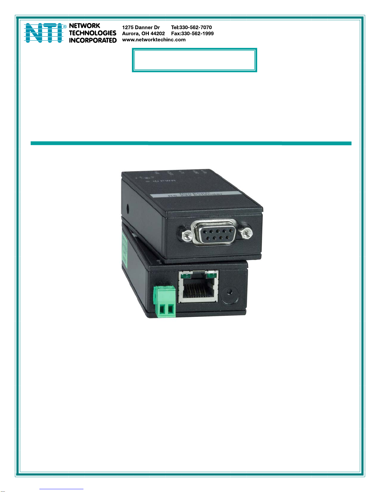
XTENDEX
®
Series
ST-C5RS-LC
RS232 EXTENDER
Installation and Operation Manual
ST-C5RS-LC
S232 Extender
Man249 Rev. 9/25/15
Page 2

TRADEMARK
XTENDEX is a registered trademark of Network Technologies Inc in the U.S. and other countries.
COPYRIGHT
Copyright © 2003, 2015 by Network Technologies Inc. All rights reserved. No part of this publication may be reproduced, stored
in a retrieval system, or transmitted, in any form or by any means, electronic, mechanical, photocopying, recording, or otherwise,
without the prior written consent of Network Technologies Inc, 1275 Danner Drive, Aurora, Ohio 44202.
CHANGES
The material in this guide is for information only and is subject to change without notice. Network Technologies Inc reserves the
right to make changes in the product design without reservation and without notification to its users.
Note: Shielded
and immunity requirements.
Note: CATx connection cable used between NTI XTENDEX Series Local and Remote or any XTENDEX Series products
should not be run underground, outdoors or between buildings.
WARNING: Outdoor or underground runs of CATX cable could be dangerous and will void the warranty.
CAT 5,5e, or 6 cable must be used to connect to LOCAL and REMOTE units in order to meet CE emission
i
Page 3

TABLE OF CONTENTS
Introduction....................................................................................................................................................................1
Materials.........................................................................................................................................................................1
Features and Functions................................................................................................................................................2
Limitations .....................................................................................................................................................................3
Preparation for Installation...........................................................................................................................................3
Installation......................................................................................................................................................................4
Cable Connections ......................................................................................................................................................4
Plug-in and Boot Up.....................................................................................................................................................5
DIN Rail Mounting........................................................................................................................................................6
Technical Specifications ..............................................................................................................................................7
Interconnection Cable Wiring Method ........................................................................................................................7
Warranty Information....................................................................................................................................................8
TABLE OF FIGURES
Figure 1- Connect Local extender to CPU.........................................................................................................................................4
Figure 2- Connect the Remote extender to the device ......................................................................................................................4
Figure 3- Connect CATx cable...........................................................................................................................................................5
Figure 4- Connect optional power supply...........................................................................................................................................5
Figure 5- View looking into RJ45 female............................................................................................................................................7
ii
Page 4
NTI XTENDEX RS232 Extender
INTRODUCTION
The XTENDEX® RS232 Extender extends one RS232 serial device up to 3,935 feet (1,200 meters) over a single CAT5e/6/7
cable.
Features Include:
• Full duplex data communication.
• Compatible with all RS232 protocols.
• Sends RS232 data at 921.6 kbps up to 328 feet (100 meters) and 115.2 kbps up to 3,935 feet (1,200 meters).
• Supports Plug-n-Play specifications.
• Pure hardware design, no software or drivers required.
• DIN-rail mountable
• Ideal for many applications, including:
o Extending serial touch screen monitors.
o Transferring data or files between computers.
Power
•
Supports self-powered devices.
• Powered by attached devices though DB9 serial cable.
• If additional power is required, a 9-30VDC power supply can be wired to the screw terminal pair (sold separately).
Regulatory Approvals
•
CE, FCC, RoHS
MATERIALS
Materials supplied with ST-C5RS-LC:
9 NTI XTENDEX RS232 Extender- Master and Slave Unit
9 2- DIN Rail mounting clips with screws
9 One 6-inch DB9 male-to-male null modem serial cable
9 CD with a pdf file of this owner's manual
Note: Shielded CAT5e,6 or 7 cable must be used to connect to LOCAL and REMOTE units in order to meet CE emission
requirements.
Contact your nearest NTI distributor or NTI directly for all of your KVM needs at 800-RGB-TECH (800-742-8324) in US & Canada
or 330-562-7070 (Worldwide) or at our website at http://www.networktechinc.com and we will be happy to be of assistance.
1
Page 5

NTI XTENDEX RS232 Extender
FEATURES AND FUNCTIONS
1. Green “Tx” LED- flashes when data is being transferred
2. Yellow “Rx” LED- flashes when data is being received
3. CAT5- RJ45 female- for connecting the CAT5e/6/7 cable
4. Terminal Block- for connecting 9-30VDC power supply if required (optional- sold separately)
5. RS232 Connector- 9D female- for connecting to the RS232 port on the CPU (Master Unit) or serial device (Slave Unit)
6. PWR- connection jack for an AC adapter (3.5x1.3mm DC Plug)- another alternate power connection method
7. LED- Illuminates red when power has been supplied to the extender
1 2
3
4
7
6
(ON SIDE)
5
2
Page 6

NTI XTENDEX RS232 Extender
LIMITATIONS
• Hot-plugging of devices is supported provided devices were originally connected at power-up.
• The extender supports all baud rates up to 115,200 baud up to 3,935 feet (1,200 meters) or 921,600 baud up to 328 f eet
(100 meters) and the attached CPU must be configured accordingly.
PREPARATION FOR INSTALLATION
• Locations should be chosen for the serially-controlled device and CPU that also has space to connect the Master and Slave
Units within the distance provided by the cables.
• The CATX cables must be run to the locations where the Master and Slave Units will be connected. Be careful to route the
cables away from any sources of magnetic fields or electrical interference that might reduce the quality of the video signal
(i.e. AC motors, welding equipment, etc.).
• All cables should be installed in such a way that they do not cause stress on their connections to the equipment. Extended
lengths of cable hanging from a connection may interfere with the quality of that connection. Secure cables as needed to
minimize this.
• Properly shut down and disconnect the power from the CPU and serial device to be separated. If other equipment is
involved whose connections are being interrupted, be sure to refer to the instruction manuals for that equipment for proper
disconnection and re-connection procedures before procee ding.
• Master and Slave units should be grounded through either a serial device or CPU that uses a 3-prong power cord. If only one
unit is grounded, shielded CAT5 cable should be used.
Note: CATX connection cable used between NTI XTENDEX Series Master and Slave or any XTENDEX Series products
should not be run underground, outdoors or between buildings.
WARNING: Outdoor or underground runs of CATX cable could be dangerous and will void the warranty.
3
Page 7

NTI XTENDEX RS232 Extender
INSTALLATION
Cable Connections
1. Connect a DINT-xx cable (9DB male to 9DB female wired straight through, pin-to-pin) cable between the DB9
connector on the Master (see label on back of extender) and the serial port on the back of the CPU (or other serial
controlling device).
Figure 1- Connect Local extender to CPU
2. Connect the supplied 6 inch 9DB male to 9DB male null serial cable between the Slave (see label on back of extender) and
your self-powered serially-controlled device.
Figure 2- Connect the Remote extender to the device
4
Page 8

NTI XTENDEX RS232 Extender
3. Connect a CAT5e/6/7 cable between the Master and Slave units. For devices controlled by up to 115,200 baud rate, this
cable can be up to 3935 feet in length (1200 meters). For devices controlled by higher baud rates (up to 921,600), this cable can
be up to 328 feet in length (100 meters).
Figure 3- Connect CATx cable
Plug-in and Boot Up
1. Power up the CPU and extended device. The red power LED on each extender should illuminate. Try sending
communication between the CPU and the serially-controlled devic e. T he CPU and device should each react as if they were
directly connected to each other.
Note: The yellow (“Tx”) and green (“Rx”) LEDs on each RJ45 connector will flash anytime data traffic is passing between
the Master and Slave, indicating proper CATx cable connection and communication.
If insufficient power is provided by the connection to the CPU or the serial device, the red power LED will not illuminate. In this
case, an external power supply (9-30VDC) will need to be connected (sold separately- contact NTI).
Figure 4- Connect optional power supply
5
Page 9

NTI XTENDEX RS232 Extender
DIN Rail Mounting
The extenders can be easily DIN rail mounted with the provided DIN rail mounting clips. Connect the clip to the extender using
the two holes on the back of the extender (screws are provided).
Spring clips
Then set the extender on the rail against the spring clips side first, apply a small amount of pressure and rotate the extender up to
lock the rail into the top of the clip. (See images below.) Release the extender to fully engage the clip on the rail.
Install screws
to secure clip
to extender
Rear View
Front View
6
Page 10

NTI XTENDEX RS232 Extender
TECHNICAL SPECIFICATIONS
RS232 Connectors 9DB female
RS232 Baud Rate 115,200 to 3935 feet (1200 meters)
RS232 Compatibility RXD,TXD,RTS,CTS
Communication Mode Full Duplex Data
RS232 protocols supported All
Interconnect Cable CAT5e/6/7 straight through cable for EIA/TI A 568 B wiring terminated w/ male
Remote and Local Unit Power device powered through 9DB cable
Power Consumption 40mA / 360mW
Operating Temperature -30°C to 75°C
Operating humidity 5 - 95% Non-Condensing
Dimensions WxDxH (In.) (Local or Remote) 1.63x3.13x0.88
Drivers required none
Regulatory Approvals CE,FCC,RoHS
921,600 to 328 feet (100 meters)
RJ45 connectors
Optional: 9-30VDC adapter (if needed)
INTERCONNECTION CABLE WIRING METHOD
The connection cable between the Remote and Local is terminated with RJ45 connectors and must be w ired according to the
EIA/TIA 568 B industry standard. Wiring is as per the table and drawing below.
1 White/Orange 2 T
2 Orange 2 R
3 White/Green 3 T
4 Blue 1 R
5 White/Blue 1 T
6 Green 3 R
7 White/Brown 4 T
8 Brown 4 R
Figure 5- View looking into RJ45 female
9DB Female on Extender
Pin Function
1 N/U
2 TXD
3 RXD
4 N/U
5 GND
6 N/U
7 CTS
8 RTS
9 N/U
N/U = Not Used
Pin Wire Color Pair Function
Pair 3
Pair 2 Pair 1
T
T
R
R
3
1
2
4
+
+
-
-
Pair 4
T
5
+
R
R
T
8
6
7
+
-
-
7
Page 11

NTI XTENDEX RS232 Extender
9DB Male to 9DB Male Null Serial Cable Pin Assignments
9DBM Signal 9DBM Signal
1 --- Not connected 1 --2 TXD 3 RXD
3 RXD
4 ---- Not connected 4 ----
5 GND Connected to 5 GND
6 --- Not Connected 6 ----
7 CTS 8 RTS
8 RTS
9 --- Not Connected --- ----
Connected to
Connected to
2 TXD
7 CTS
WARRANTY INFORMATION
6 Inch Cable
(Supplied)
The warranty period on this product (parts and labor) is two (2) years from the date of purchase. Please contact Network
Technologies Inc at (800) 742-8324 (800-RGB-TECH) or (330) 562-7070 or visit our website at http://www.networktechinc.com
for information regarding repairs and/or returns. A return authorization number is required for all repairs/returns.
Note: CATx connection cable used between NTI XTENDEX Series Local and Remote or any XTENDEX Series products
should not be run underground, outdoors or between buildings.
WARNING: Outdoor or underground runs of CATx cable could be dangerous and will void the warranty.
Manual 249 Rev. 9/25/15
8
 Loading...