

Page 1
Visit us
online
WF200 – Wood Fired Boiler
INSTALLATION AND OPERATION MANUAL
Version Date: 2018-05-07
SAVE THESE INSTRUCTIONS
TABLE OF CONTENTS
HAZARD SYMBOLS AND DEFINITIONS
Danger Sign: Indicates a hazardous situation which, if not avoided, will
result in serious injury or death.
Warning Sign: Indicates a hazardous situation which, if not avoided,
could result in serious injury or death.
Caution Sign plus Safety Alert Symbol: Indicates a hazardous situation
which, if not avoided, could result in minor or moderate injury.
Caution Sign without Safety Alert Symbol: Indicates a hazardous
situation which, if not avoided, could result in property damage.
Notice Sign: Indicates a hazardous situation which, if not avoided,
could result in property damage.
This Boiler must be installed by a licensed and trained Heating
Technician or the Warranty is Void. Failure to properly install this
unit may result in property damage, serious injury to occupants, or possibly death.
30 Stonegate Dr.,
Saint John, NB,
E2H 0A4
NTI # 86241
Page 2
2
Installation and Operation Manual WF200
1.0 INTRODUCTION
Read Before Proceeding
The installation of your NTI Wood Fired boiler must conform to the requirements of this manual, your local
authority, and the latest edition of CSA standard B365 Installation code for solid-fuel-burning appliances and
equipment.
This document pertains to the correct installation and operation of NTI Wood Fired boiler model WF200. The
instructions detailed in this document supersede any and all previous instructions provided by NTI, written or
otherwise.
Read and understand this entire document prior to proceeding with the installation of the
WF200 Wood Fired boiler. Failure to follow the instructions outlined in this document
will result in property damage, serious injury or death.
Void Warranty - This Boiler must be filled with water at all times, whenever it is
operated, otherwise overheating will occur, damaging the unit (voiding the warranty) and
possibly resulting in fire or explosion.
Do not store or use gasoline or other flammable vapors and liquids in the vicinity
of this or any other boiler. Failure to follow instructions may result in serious
injury or death.
Chimney Fires or Runaway Fires
Have a clear and understood plan for handling a chimney fire:
Close all sources of air to the fire (including the draft regulator).
Evacuate the house and call the fire department.
Wet-down combustible materials adjacent to the chimney.
Do not remove flue pipe until fire is completely out.
Do not use the chimney again until it has been inspected and repaired, if necessary.
By following these basic steps you will bring the fire under control. The time it takes to bring it under control
depends upon the amount of fuel in the boiler and the rate at which it is burning at the time it is detected.
User Responsibilities
As the User/Owner of this equipment, you are responsible for ensuring this appliance is operated and maintained
in accordance with these instructions; see Section 7.0 – Installation & Operation Checklist and Section 8.0 –
Annual Maintenance and Inspection.
Installer Responsibilities
As the installing technician it is your responsibility to ensure the installation is performed in accordance with this
instruction manual as well as any applicable local or National installation codes. It is also your responsibility to
inform the User/Owner of their obligation with respect to the above description under “User Responsibilities”.
Failure to follow this warning could result in fire, serious injury, or death.
Failure to properly operate and maintain the boiler, including the smoke pipe and
chimney, may result in property damage, serious injury or death.
Page 3
3
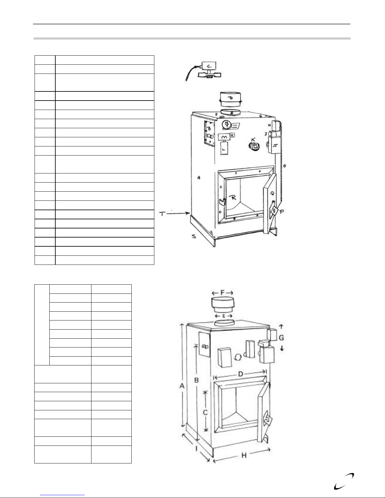
A
Flush Jacket
B
Domestic Coil
C
Normally Open Zone Valve
V8043D1
D
Relief Valve Tapping
E
Flue
F
Relief Valve Tapping
G
Supply Tapping
H
Damper Motor M847A1031
I
Transformer AT20B1064B
J
Aquastat L4081A1155
K
Pressure & Temperature
Gauge
L
Aquastat L4006B1007
M
Fan Center R8285A1048
N
Transformer AT20B1064B
O
Damper Chain
P
Damper Door
Q
Fire Door
R
Combustion Area
S
Base
T
Return Tapping
U
Low water cut off
Dimensions
A
42” B
37”
C
13½”
D
15¾”
E
8” F 7” G 7”
H
22½”
I
30”
Chamber size
(HxWxD)
18 x 16 x
25.5
Supply
1 ½”
Return
1 ½”
Relief Valve
¾”
Drain
½”
Heating
Surface (sq. Ft)
20
Weight (lbs)
625
Water volume
(Imp. Gal)
43
Tapping provided for
¾” Low water cut-off
Model OEM 170
Safeguard
WF200 Installation and Operation Manual
2.0 SPECIFICATIONS
Parts Diagram
Dimensions
Page 4
4
Installation and Operation Manual WF200
3.0 BOILER LOCATION
In all cases, the WF200 boiler must be installed indoors in a dry location where the ambient temperature must be
maintained above freezing and below 100F [38C]. All boiler components must be protected from dripping,
spraying water, or rain during operation and servicing. Consider the proximity of system piping, electrical
supply and chimney termination when determining the best boiler location.
Air for Combustion & Ventilation
Protection against depressurization – the WF200 boiler operates on natural draft, therefore the space containing
the boiler must not be susceptible to becoming depressurized. Follow the direction outlined in section 5.1.3 of
CAN/CSA B365, Installation code for solid-fuel-burning appliances and equipment, to determine if a makeup
air system is required.
Ventilation air supply in confined spaces – when installed in an enclosed space, with a volume less than 20% of
the space being heated by the wood fired boiler, the space shall:
a) have a permanent opening or openings for natural air circulation with a minimum net free area of 150 in2;
and
b) be connected to another space or spaces such that the total volume of air available for natural air
circulation is at least 30% of the total volume to be heated by the wood fired boiler.
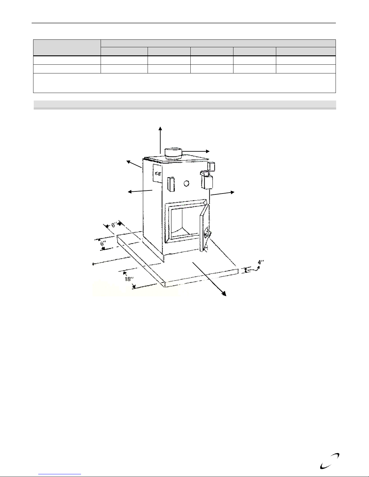
Clearance to Combustible Material
Place boiler on a non-combustible floor (see Foundation below), observe the minimum clearances to combustible
material listed in Table 3-1 and illustrated in Figure 3-1.
Foundation – The boiler should never be installed on a combustible floor or base. Foundations shall be installed
with the following minimum dimensions (see Figure 3-1):
4 in. thick
Extended 6 in. beyond the boiler sides and back.
Extend 18 in. in front of the boiler
Water or flood damaged components must be replaced immediately with new factoryapproved components as failure to do so may result in fire, serious injury, or death.
A makeup air system need not be installed if a spillage detection and alarm system (e.g. a
carbon monoxide alarm) is installed in accordance with local regulations, or the National
Building Code.
The minimum dimension of any opening as specified in (a) above, shall be no less than 1
in. The lower edge of at least one opening shall be located within 1.5 ft of the floor of the
enclosed space, and the upper edge of at least one opening shall be located within 1.5 ft of
the ceiling of the enclosed space.
Failure to adhere to the installation clearances and restrictions detailed in these
instructions can lead to risk of fire or explosion resulting in property damage, personal
injury or death.
Wood Storage – Maintain a minimum clearance of 5 ft. between the wood boiler and a
woodpile; the space around the boiler should be kept clean and free of litter and wood
residues. Where fans are used in the wood storage area, they should be installed so as not
to create negative pressures in the room where the wood boiler is located.
Page 5
5
Clearances
Dimensions
Front
Top
1
Sides 2 Rear
Flue Pipe
Minimum
48 in.
6 in.
6 in.
24 in.
18 in.
Recommended
60 in.
36 in.
24 in.
36 in.
18 in.
Notes:
1
Space above boiler shall NOT be used for storage.
2
With hot water coil installed, the coil side requires a minimum of 24 in. clearance.
Figure 3-1 Minimum Clearances to Combustibles
24” or 6”
24”
6”
48”
6”
18”
WF200 Installation and Operation Manual
Table 3-1 Minimum Clearances for Installation and Service
Page 6

6
Minimum Thickness of Metal used in Chimney Connector
Diameter of Flue Pipe, in.
Minimum Thickness, in.
7-8
0.021
Installation and Operation Manual WF200
4.0 VENTING FLUE GASES
The WF200 Wood Fired boiler shall be safely vented to the outdoors in accordance with these instructions,
CAN/CSA B365, Installation code for solid-fuel-burning appliances and equipment, and the National Building
Code.
Chimney
Only a chimney meeting one of the criteria listed below (a or b) shall be used to vent the flue gases from the
WF200 boiler. When connecting to an existing chimney it must be inspected thoroughly before firing the
equipment.
a) a masonry chimney conforming to provincial or territorial regulations or bylaws, or in the absence
thereof, to the National Building Code; or
b) a factory-built chimney conforming to CAN/ULC-S629; often referred to as “All-fuel” chimneys (Not
Applicable for U.S. installations). The appropriate clearance of these chimneys from combustible
materials is specified in the manufacturer’s installation instructions and also the listing label of the
chimney selection.
The chimney and flue pipe must be clean and in good condition to avoid the risk of fire.
Chimney Connector
Usually a few feet of flue pipe (single wall) are used to connect the boiler to the chimney and in such cases, this
section of the venting system is called a chimney connector. A great number of fires associated with wood
burning appliances are due to unsafe connector installations. The following requirements are designed to prevent
two hazards: 1) ignition of the surroundings, principally by radiant heating, and 2) inadequate draft, which could
result in serious smoke concentrations in the house. The minimum thickness of steel used for the chimney
connector must conform to the Table below.
Each flue joint should be secured with at least 3 metal screws or equivalent. Outside mechanical support should
be used if the connector is more than 6 feet long. The flue pipe should be accessible for inspection, cleaning and
possible replacement. If the flue pipe connects to an existing chimney, the pipe should penetrate through the
inner surface of the masonry wall, but not beyond (not into the space itself). The connection should be made
physically secure such as through the use of high temperature cement.
A flue pipe serving a solid fuel appliance shall:
a. Be securely supported by metal or other non-combustible supports.
b. Be as short and straight as possible.
c. Not exceed a maximum 10-foot horizontal run.
d. Be designed and constructed to allow for expansion.
e. Be sloped upward toward the chimney at least ¼ inch per foot of horizontal run.
f. Have a cross-section area no less than: 1) The area of the flue outlet of the appliance served by a flue pipe,
2) The combined area of the flue outlets of all the appliances served by a breeching.
g. Enter the side of a chimney through an approved metal thimble or masonry flue ring.
h. Not extend into the chimney flue.
i. Have a tight connection with the chimney.
j. Have installed at least three sheet metal screws to secure each length of flue pipe where they are joined and
where it is attached to the wood boiler flue outlet.
k. A flue servicing a solid fuel fired appliance should not pass through:
1. Attic or roof space, closet or similar concealed space
2. A floor, ceiling, wall or partition of combustion construction.
Page 7

7
Figure 4-1 Venting Hookup
WF200 Installation and Operation Manual
For installations in the U.S., wood boilers require a barometric damper be installed in the
Chimney Connector.
Manual Draft Dampers – when installed, should provide no more than 80% closure when fully shut, and must
also be installed on a short piece of flue pipe that is easily removed to facilitate cleaning.
Manual Draft Dampers are only recommended in applications with very high draft
conditions. When installed, manual draft dampers
Page 8

8
Installation and Operation Manual WF200
5.0 BOILER SYSTEM PIPING & CONTROL WIRING
Failure to follow the instructions provided in this section will void the NTI warranty and
may result in property damage, fire, serious injury or death.
Installation and set-up of the Boiler System Piping and Control Wiring for the WF200 will depend largely on the
application it is being used in. This section of the manual details the two basic types of applications:
(1) WF200 installed as an Add-on to an oil boiler
(2) WF200 installed as a Stand-alone boiler
Regardless of the application, follow the instructions detailed under General Field Wiring and General
Boiler System Plumbing, as these instructions are common to all applications of the WF200 boiler. As the
specific application dictates, follow all instructions detailed under WF200 Installed as an Add-on to an Oil
Boiler, or WF200 Installed as a Stand-alone Boiler.
General Field Wiring
All wiring must be in accordance with the Canadian Electrical code, CSA C22.2 and any applicable local codes.
Ensure that the wiring complies with this manual. The boiler must be electrically grounded in accordance with
the National Electrical Code ANSI/NFPA 70, local codes, and/or the Canadian Electrical Code CSA C22.1.
Avoid Shocks - To Avoid Electrical Shock, turn off electrical power to the boiler prior to
opening any electrical box within the unit. Ensure the power remains off while any
wiring connections are being made. Failure to follow these instructions may result in
component failure, serious injury or death.
Wire Protection - use wire grommets suitable for securing the wiring and preventing
chafing, at each junction box / electrical device. Failure to follow instructions may result
in component failure and/or electrical shock causing serious injury or death.
Power Supply (120V / 1 Phase / 60 Hz / 12A) - The WF200 is designed to be powered
using a single phase 120VAC power supply that is fused (or protected via a circuit
breaker) to allow a maximum of 15 Amps. Failure to follow instructions may result in
component failure, serious injury or death.
Labeling - Label all wires prior to disconnecting them when servicing controls. Wiring
errors can cause improper and dangerous operation. Failure to follow instructions may
result in property damage or personal injury.
Continuity - Before connecting the line voltage wiring, perform a continuity check
between all wires and ground to make sure that there are no electrical leaks that could
blow a fuse or damage electrical components. Also check the polarity of the line and
neutral wires. Line must measure 120VAC to ground; neutral must measure zero.
Failure to follow instructions may damage the unit.
Page 9

9
Table 5-1 Boiler System Cleansers and Corrosion Inhibitors
Application
Fernox Product
NTI Part #
Description
Boiler Water Treatment
F1 Protector
83448
Corrosion inhibitor.
Cleanser for new and old systems
F3 Cleaner
83449
Removes flux, grease and carbon residue.
Cleanser for Retrofits
DS-40 System Cleaner
83450
Removes heavy limescale and sludge deposits.
WF200 Installation and Operation Manual
General Boiler System Plumbing
Prior to connecting plumbing to the boiler, flush the entire system to ensure it is free of sediment, flux, solder,
scale, debris or other impurities that may be harmful to the system and boiler. During the assembly of the
heating system, it is important to keep the inside of the piping free of any debris including construction and
copper dust, sand and dirt.
For retrofits, all system piping, including radiators, must be cleansed of build-up including sludge and scale. All
systems, old and new, must be cleansed to remove flux, grease and carbon residue; NTI recommends cleaning
the boiler system with “Fernox F3 Cleaner”. For retrofit applications with heavy limescale and sludge deposits,
a heavier duty cleaner may be required; NTI recommends the use of “Fernox DS-40 System Cleaner”. For
information on performing the cleaning, follow the instructions included with the applicable Fernox Cleaner.
See Table 5-1 for a list of recommended boiler system cleaning and treatment products.
Failure to rid the heating system of the contaminants listed above will void your NTI
warranty and may result in premature heat exchanger failure and property damage.
Oxygen Elimination - This boiler may only be installed in a pressurized closed-loop heating system, free of air
and other impurities. To avoid the presence of oxygen, ensure all of the air is removed from the system
during commissioning via strategically placed, adequately sized air-removal devices; located throughout the
heating system. Immediately repair any leaks in the system plumbing to avoid the addition of make-up
water; make-up water provides a source of oxygen and minerals that may lead to heat exchanger failure.
Failure to follow these instructions will result in poor performance, unnecessary wear of system components
and premature failure.
The WF200 Wood Boiler is not approved for operation in an “open system”, thus it
cannot be used for direct potable water heating or process heating of any kind.
Pressure – WF200 Wood Boilers are intended solely for use in pressurized closed-loop heating systems
operating with a minimum pressure of 15 PSI at the boiler outlet.
Pressure Relief Valve – A Pressure Relief Valve is factory supplied with each unit. WF200 boilers have a
maximum allowable operating pressure of 30 PSI. The pressure relief valve must be installed at the top of
the boiler (see Figures 5-1 & 5-3), with no isolation valves between it and the boiler heat exchanger. It must
be oriented in the vertical position, with the drain pipe outlet exiting the side of the pressure relief valve
horizontally and elbowing downward.
If installed in the incorrect orientation (horizontally with drain pipe out the bottom) the
relief valve may not function properly resulting in property damage or personal injury.
Ensure the discharge of the pressure relief is piped to a location where the steam or water
will not cause property damage or serious injury.
Pressure & Temperature Gauge – WF200 boilers come with a factory supplied Pressure and Temperature
Gauge. The gauge must be installed in the fitting provided in the front of the boiler.
Wood Boiler Circulating Pump – A circulating pump is provided with each WF200, install as illustrated in
Figures 5-1 through 5-4, and as per the manufacturer’s instructions provided with the pump.
Page 10

10
Factory Supplied Components
Field Supplied Components
Pressure Relief Valve
L8124A Aquastat (or Equivalent) – existing on Oil Boiler, or used
to activate Wood Boiler Circulator and Damper Motor for Add-on
applications
Pressure/Temperature Gauge
Wood Boiler Circulating Pump
Normally Open Zone Valve (Dump Zone)
Central Air Removal Devices (i.e. Micro Bubbler or Air-Scoop)
L4081 Aquastat – activates Dump Zone (&
Damper Motor for Add-on applications)
Pressure Regulating “Fill Valve”
Damper Motor
Backflow Preventer
L4006B Aquastat – activates Wood Boiler
Circulating Pump for Add-on applications
Expansion Tank
Installation and Operation Manual WF200
Table 5-2 System Major Component Checklist
Expansion Tank – The expansion tank must be sized in accordance with the water volume of the system as well
as the firing rate of the appliance. It is important to locate the expansion tank in accordance with Figures 5-1
& 5-3
Ensure the expansion tank cannot become isolated from the boiler anytime the system is
operating. Failure to follow these instructions may result in discharge of the Pressure
Relief Valve may result in property damage or personal injury.
Normally Open Zone Valve (Dump Zone) – A normally open zone valve is factory supplied, and must be used
in the installation of a hot water circulation loop (or Dump Zone) designed to dissipate at least 10% of the
Approximate Firing Rate of the WF200 in the event that circulation is reduced because of electrical power
failure; see Figures 5-1 through 5-4. It is recommended to position the dump zone above the boiler, and to
design to loop to promote natural thermal circulation. Design parameters for sizing the Dump Zone shall
include:
(1) minimum pipe size of ¾ in. ID,
(2) room ambient temperature of 18°C (65°F), and
(3) a mean water temperature of 82°C (180°F)
Dump Zone – the hot water recirculation loop shall only be made inoperative by a
deliberate manual action. Failure to implement and maintain a recirculation loop able to
dissipate a minimum of 10% of the rated firing rate of the WF200 in the event that
circulation is reduced because of electrical power failure, may lead to excessive water
temperatures causing property damage fire or personal injury.
Before putting water into a new boiler, make sure that the fireside is ready for operation
(Note: do not light a fire in an empty boiler). Once water is introduced, and air is mostly
purged, operate the fireside to bring the boiler water up to temperature. This is necessary
because raw water must be heated to at least 180 ºF immediately after it is introduced into
the boiler, in order to drive off the dissolved gases, which might otherwise corrode the
boiler.
Page 11

11
Figure 5-1 WF200 Installed as an Add-on to an Oil Boiler – Plumbing Arrangement
A
Existing Oil Boiler
B
WF200 Wood Boiler
C
Existing Heating Circulator
D
Wood Boiler Circulator
E
Isolation Valves
F
Expansion tank
G
Zone Valves (N.C.)
H
Dump Zone Valve (N.O.)
I
Existing Fill/Backflow Valve
J
Pressure Relief valve
K
L4006B Aquastat
L
L4081A Aquastat
M
Damper Motor
N
Existing Boiler Aquastat
O
Flow Check Valve
P
Swing Check Valve
Q
Water Supply
R
Existing system Return
S
Existing Boiler Supply
T
Supply to Zones
WF200 Installation and Operation Manual
WF200 Installed as an Add-on to an Oil Boiler
The WF200 is factory supplied with controls necessary for a typical installation as an add-on to oil boiler. In
addition to the preceding General Field Wiring and the General Boiler System Plumbing instructions, use the
follow instructions to complete the plumbing and wiring for a WF200 installed as an add-on to an oil boiler.
Additional Wiring Guidelines for Oil Add-ons:
Power both boilers from a single electrical circuit.
Wire the system in accordance with Figure 5-2 – deviating from this could negate important safety
shutdown mechanisms – possibly leading to a “runaway boiler”.
Enclosures of control devices are not to be used as junction boxes to extend supply circuits from one
boiler to the other.
Upon completion of the installation, adjustments of any controls, other than the room thermostats, should
not be required when changing from one fuel to the other.
Page 12

12
Figure 5-2 WF200 Installed as an Add-on to an Oil Boiler – Wiring Diagram
No.
NTI P/N
Model
Operation
1
13905
L4006B
SPST switch makes on temp. Rise to set point. Breaks on fall from set point minus
differential. On rise R W contacts close energizing wood circulator, and at the same time
power R8239A relay to de-energize N.C. Contacts in relay so the oil burner cannot
operate.
2
81313
R8285a
or
8A05A-101
Used as isolating relay. Will not allow oil burner to operate when wood circulator is
running. Oil burner is powered from L8124A triple aqua stat through N.C. contacts in
the R 8239A relay which contacts are open when wood circulator is powered through
L4006B.
3
13902
or
81876
L4081A
or
11D05-1
2-SPST switches. Both break on rise, one acts as controller powering M847 damper
motor on temperature fall. The other is a high limit switch wired in series with the
controller. The high limit switch breaks power to both damper motor and N.O. damp
zone valve. End switch of N.O. valve is connected to TT of L8124A triple aquastat to
bring oil circulator on when temperature in wood boiler exceeds high limit setting of L
4081A aquastat.
Wood Boiler Pump
System Pump
Oil Burner
Dump Zone Valve
Transformer
120/24VAC
Transformer
120/24VAC
Damper
Motor
Installation and Operation Manual WF200
Suggested Control Settings for Oil Add-ons:
Oil boiler Aquastat (e.g. L8124A) – HI 200º, LOW 180º, Diff 10º
Wood boiler Aquastat / Pump control (L4006B) – HI 190º, Diff 10º
Wood boiler high limit (L4081A) – HI 220º, LOW 200º
Page 13

13
WF200 Installation and Operation Manual
Control Sequence for Oil Add-on:
1. Standby ( T T Open, No Wood Fire ) – Oil boiler operates as normal.
2. Standby ( T T Open, Wood Fire) – When the temperature in wood boiler rises to the set point of the
L4006B control, the wood circulator is energized (pumping wood boiler water into the existing oil boiler),
and power is energized to the switching relay Pn. 81313. This will interrupt power to the burner through the
“Normally closed” contacts in the relay.
3. Domestic Coil (T T Open) – If there is a call for domestic hot water, the oil boiler will remain OFF unless
the temperature drops below the L4006B setting.
4. Call For Heat (T T Closed Wood Fire) – When there is a call for heat, the oil boiler operates normally. If
the temperature of the wood boiler is higher than the setpoint of the L4006B, the burner will be prevented
from operating (normally closed contacts of switching relay, Pn. 81313). The wood circulator is energized
pumping the wood boiler water into the existing oil boiler and into the house.
5. Call For Heat (T T Closed, No Wood Fire) – Oil boiler operates as normal.
6. Wood Boiler Exceeds L4081A LOW Limit Setting (200F) – Power to the Damper Motor (M) is
removed, thereby closing the wood boiler dampers and reducing the flow of combustion air to the flame.
7. Wood Boiler Exceeds L4081A HI Limit Setting (220°F) – In addition to cutting power to the Damper
Motor, power to the Dump Zone Valve (H) is also removed, thereby opening the normally open Dump
Zone Valve – causing its end-switch to close - which energizes TT of the oil boiler Aquastat. The Oil
boiler Aquastat then initiates the Heating Circulator, forcing water circulation through the Dump Zone.
8. Power Failure – Wood boiler dampers closes and the Dump Zone Valve opens; water will flow by gravity
around the dump zone loop. NOTICE: the Dump Zone should be the largest zone in the house.
Add wood according to the temperature outside. Overfilling will make the dampers close
for extended periods of time creating creosote in the chimney.
Page 14

14
Figure 5-3 WF200 Installed as Stand-alone – Plumbing Arrangement
B
WF200 Wood Boiler
C
Wood Boiler Circulator
E
Isolation Valves
F
Expansion tank
G
Zone Valves (N.C.)
H
Dump Zone Valve (N.O.)
I
Existing Fill/Backflow Valve
J
Pressure Relief Valve
K
L8124A Aquastat or Equivalent
(field supplied)
L
L4081A Aquastat
M
Damper Motor
Q
Water Supply
R
Heating System Return
S
Heating System Supply
T
Supply to Zones
Figure 5-4 WF200 Installed as Stand-alone – Wiring Diagram
Installation and Operation Manual WF200
WF200 Installed as Stand-alone Boiler
The WF200 is factory supplied with controls necessary for a typical installation as an add-on to oil boiler; when
installed as a stand-alone, the installer must supply a high limit Triple Aquastat (e.g. L8124A) to operate the
damper motor and circulator. In addition to the preceding General Field Wiring and the General Boiler
System Plumbing instructions, use the follow instructions to complete the plumbing and wiring for a WF200
installed as a stand-alone boiler. It is strongly recommended to utilize a bypass line between the supply and
return, as a wood burning unit does not recover cold water return as quickly as an oil burning unit.
Page 15

WF200 Installation and Operation Manual
15
Suggested Control Settings for Stand-alone Application:
Wood boiler Aquastat (e.g. L8124A) – HI 200º, LOW 180º, Diff 10º
Wood boiler high limit (L4081A) – HI 220º, LOW NA
Control Sequence for Stand-alone Application:
1. Standby ( T T Open) – When the temperature in wood boiler rises to the LOW Limit set point of the
L8124A (K) control, power to the Damper Motor (M) is removed, thereby closing the wood boiler dampers
and reducing the flow of combustion air to the flame. Power to the Damper Motor is reapplied when the
temperature drops below the LOW Limit setting minus the DIFFERENTIAL setting.
2. Domestic Coil (T T Open) – Power to the Damper Motor is applied when the temperature drops below the
LOW Limit setting minus the DIFFERENTIAL setting, thereby opening the dampers.
3. Call For Heat (T T Closed) – Damper Motor stays powered until the temperature exceeds the HI Limit
setting of the L8124A. The Wood Boiler Circulator (C) stays powered until the temperature drops below
the LOW Limit setting of the L8124A.
4. Wood Boiler Exceeds L4081A HI Limit Setting (220°F) – Power to the Dump Zone Valve (H) is
removed, thereby opening the normally open Dump Zone Valve – causing its end-switch to close – which
energizes TT of the wood boiler Aquastat (L8124A). The L8124A then initiates the Wood Boiler
Circulator, forcing water circulation through the Dump Zone.
5. Power Failure – Wood boiler dampers closes and the Dump Zone Valve opens; water will flow by gravity
around the dump zone loop. NOTICE: the Dump Zone should be the largest zone in the house.
Add wood according to the temperature outside. Overfilling will make the dampers close
for extended periods of time creating creosote in the chimney.
Page 16

16
Figure 6-1 Connecting Damper Motor to Air Dampers
Procedure:
1. Install Damper Motor
2. Install Upper Chain – with the power off and the Air
Dampers closed, connect a piece of chain from the Damper
Motor Armature, at approximately the 7 o’clock position,
to the Top Air Damper. Leave approximately 1-2 chainlinks of slack.
3. Install Lower Chain – use a second piece of chain to link
the top and bottom Air Dampers together. Leave 2-3
chain-links of slack, i.e. slightly more slack than the upper
chain.
4. Test (Power Off) – with the power off, both dampers
MUST BE FULLY CLOSED. If not fully closed, adjust
chains and/or Air Damper Arms accordingly.
5. Test (Power On) – as the Damper Motor turns, rotating
clockwise from the 7 o’clock position, the Top Air Damper
will begin to open, shortly followed by the Bottom Air
Damper. The timing between the opening of the two Air
Dampers is accomplished by the increased slack of the
lower chain, and is necessary to avoid excess strain on the
Damper Motor. If adjustments to the chains or Air Damper
Arms are necessary, repeat the Power Off test to ensure the
dampers close fully during a power outage.
WF200
Left Side
Top
Air Damper
Bottom
Air Damper
1-2 Links
of Slack
Damper
Motor
2-3 Links
of Slack
Armature
Installation and Operation Manual WF200
6.0 AIR DAMPER CONTROL & OPERATION
The WF200 is equipped with two air dampers, one located on the fire chamber access door, the second directly
below. Both dampers are to be operated by a single damper motor via factory supplied chain; see Figure 6-1.
Damper Motor – A damper motor is provided with each boiler, and is to be field installed at the top-right of the
front of the WF200, so the damper motor armature is directly above the two air damper arms to allow
unhindered installation and operation of the connecting chain; see Figure 6-1.
Page 17

17
WF200 Installation and Operation Manual
7.0 INSTALLATION & OPERATION CHECKLIST
Installation Checklist
1. Locate the boiler in accordance with Section 3.0 of this manual.
2. Install the exhaust venting in accordance with Section 4.0 of this manual. Ensure all joints are secured
properly.
3. Install the controls and wiring in accordance with Section 5.0 of this manual. Choose the controls and
wiring arrangement to match the type of installation, i.e., Add-on or Stand-alone. Set controllers as
instruction in Section 5.0.
4. Connect Damper Motor to Air Dampers in accordance with Section 6.0 of this manual. Make sure the Air
Dampers are in the closed position when the Damper Motor is not powered
5. Install the plumbing in accordance with Section 5.0 of this manual; flush/cleanse the internals of the heating
system. Treat system water with Fernox F1 Protector when needed. Repair any water leaks and ensure
boiler system is purged of air. Be sure to install an appropriate Dump Zone with the normally open zone
valve.
6. Light a fire in the combustion chamber (see Operational Checklist below) to bring the boiler up to
temperature – this will take several minutes. Test the Control Sequence in accordance with Section 5.0.
7. Advise homeowner / operator of the WF200, of their responsibilities with respect to operating and
maintaining the boiler. See instructions below Operation Checklist and Section 8.0 – ANNUAL
MAINTENANCE AND INSPECTION. Leave the Installation and Operation Manual with the
homeowner.
Operation Checklist (for the homeowner / operator)
1. Ensure system is free of water leaks and pressure is maintained above 12 psi.
2. Inspect flue pipe – see “Smoke Pipe Inspection” below.
3. Maintain a minimum clearance of 5 ft. between the wood boiler and a woodpile; the space around the
boiler should be kept clean and free of litter and wood residues. Stored wood should not obstruct access
to the boiler in any way.
4. Insure that all seals on boiler are air tight to prevent over heating of boiler when combustion air damper is
shut. For safety keep fire door tightly closed, other than for adding wood.
5. Damper should be opened for 6 seconds before opening fire door. Always open door slowly, this will cut
down the possibility of creating suction and drawing smoke from combustion chamber.
6. Burn wood only – never use gasoline, oil or other liquids in fire. Never burn rubber tires or creosote
railway ties.
7. Dry wood is recommended for safety and efficiency. Green or wet wood gives kiss heat and more smoke
and creosote – check daily for creosote buildup.
8. Do not load wood above the water baffle.
9. Do not adjust draft higher than 0.5 in. H2O.
10. Never mechanically force air into the combustion chamber – the WF200 is suitable for natural draft only
– boiler is not suitable for Stoker firing.
11. Remove ash before height reaches 4 in.; remove only when fire is completely out by using a shovel and
placing ash in a steel container with a tightly fitting lid and move to the outdoors – DO NOT PLACE
OTHER WASTE IN THIS CONTAINER.
12. .
DO NOT USE CHEMICAL OR FLUIDS TO START THE FIRE.
DO NOT BURN GARBAGE, GASOLINE, NAPHTHA, ENGINE OIL, OR OTHER
INAPPROPRIATE MATERIALS.
Flue Draft – exceeding the maximum flue draft of 0.5 in. H
O could cause the boiler
2
to burn out of control causing overheating and potential fire hazard.
Smoke Pipe Inspection – The smoke pipe should be inspected on a regular basis during the heating season;
whenever possible the smoke pipe should be dismantled and cleaned out. Carefully examine the smoke pipe
for defects such as corrosion, seams coming apart, etc. If any defects are noticed the pipe should be replaced
(22-gauge galvanized stovepipe is recommended).
Page 18

18
Installation and Operation Manual WF200
Creosote Formation – When combustion is not complete or when the wood doesn’t burn completely, unburned
gases are given off. These unburned gases will be drawn through the boiler into the smoke pipe and
exhausted through the chimney; when these gases cool down, creosote results. The colder the gases get the
harder the creosote forms; the harder if forms the harder it is to remove. Creosote is still combustible and it
will burn uncontrollably if ignited. The rate of creosote formation can be limited by:
1. Burning only seasoned dry firewood – establish a routine for the proper storage of firewood, to ensure it
has an opportunity to properly dry.
2. Maintaining hot fires – add firewood according to the need for heat, therefore limiting the need for air
damper closure. A small intense fire is preferable to a large smoldering one to reduce the amount of
Prolonged Power Failure – To operate the boiler for prolonged power outages, manually open all zone valves to
creosote deposits
Solid-fuel-burning appliances need to be cleaned frequently because soot, creosote, and
ash can accumulate. Beware that the rate creosote is deposited can vary with the season,
hotter fires mean less creosote, while monthly cleanings may be sufficient in the coldest
months, weekly cleanings may be necessary during more mild weather.
allow thermal circulation (note: the normally open Dump Zone valve should already be open). Working with a
small fire, manually operate the air dampers to regulate heating – DO NOT prop or fix the dampers in the open
position. The rate of heat dissipation is limited to thermal circulation only, so regulate the fire accordingly.
NOTICE: applications where the radiation is below the level of the boiler may not provide sufficient thermal
circulation – in such applications, the boiler cannot be operated during a power outage.
Page 19

19
WF200 Installation and Operation Manual
8.0 ANNUAL MAINTENANCE AND INSPECTION
The WF200 must be inspected and serviced regularly throughout the heating season by the operator as per
Operation Checklist in Section 7.0; in addition, the boiler must be inspected and serviced annually by a Qualified
Technician.
Annual Inspection Checklist
1. Ensure system is free of water leaks and pressure is maintained above 12 psi.
2. Test the relief valve by lifting the lever.
3. Low water cut off is tested and cleaned in accordance with its instructions
4. Clean smoke pipe and chimney (the frequency of the smoke pipe and chimney cleanings will depend on
operating conditions).
5. Ensure that all seals on boiler are air tight to prevent over heating of boiler when combustion air damper is
shut.
6. Test the Control Sequence in accordance with Section 5.0; ensure proper closure of the air dampers, and
functioning of the dump zone.
7. Keep boiler area clear and free from combustible materials, gasoline, and other flammable vapors and
liquids
8. Ensure there is nothing obstructing the flow of combustion and ventilation air.
Page 20

20
Visit us
online
Installation and Operation Manual WF200
NY Thermal Inc. 30 Stonegate Dr. Saint John, NB E2H 0A4 Canada
Technical Assistance: 1-800-688-2575
Website: www.ntiboilers.com
Fax: 1-506-432-1135
 Loading...