

NTI VOPEX-C5USBVA-4, VOPEX-C5USBVA-8, VOPEX-C5USBVUA-4, VOPEX-C5USBVUA-8 Installation And Operation Manual
Page 1
NTI
NETWORK
R
TECHNOLOGIES
INCORPORATED
1275 Danner Dr
Aurora, OH 44202
www.networktechinc.com
Tel:330-562-7070
Fax:330-562-1999
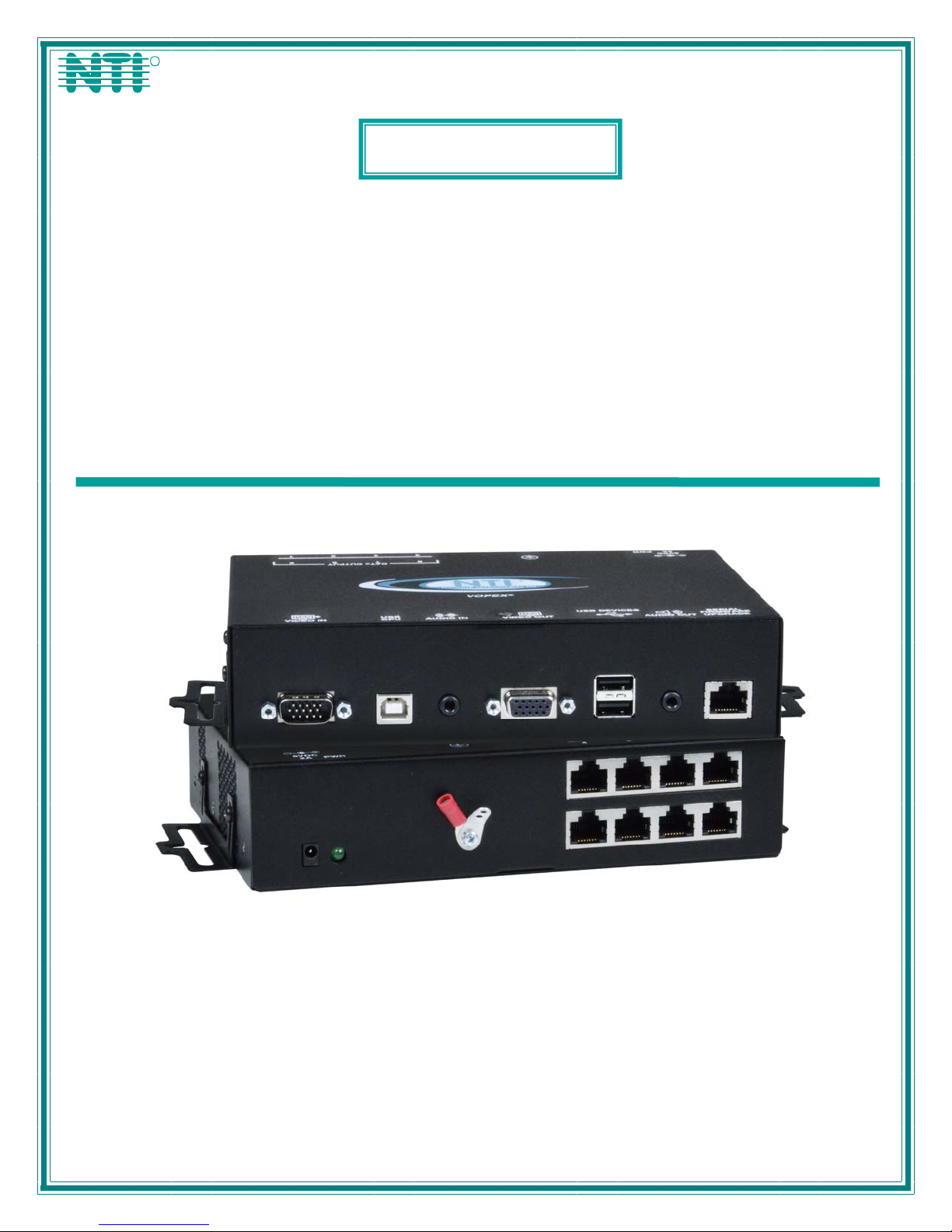
VOPEX®Series
VOPEX-C5USBVA-4 /-8
VOPEX-C5USBVUA-4 /-8
VGA Video/Audio
Splitter/Extender
Installation and Operation Manual
VOPEX-C5USBVUA-8 (Front and Rear View)
MAN208 Rev Date 11/20/2014
Page 2
TRADEMARK
VOPEX is a registered trademark of Network Technologies Inc in the U.S. and other countries.
COPYRIGHT
Copyright © 2003, 2014 by Network Technologies Inc. All rights reserved. No part of this publication may be reproduced, stored
in a retrieval system, or transmitted, in any form or by any means, electronic, mechanical, photocopying, recording, or otherwise,
without the prior written consent of Network Technologies Inc, 1275 Danner Drive, Aurora, Ohio 44202.
CHANGES
The material in this guide is for information only and is subject to change without notice. Network Technologies Inc reserves the
right to make changes in the product design without reservation and without notification to its users.
!
WARNING: Never connect a VOPEX Series VOPEX-C5USBV(A)-4 Extender/Splitter to an Ethernet card,
Ethernet router, hub or switch or other Ethernet RJ45 connector of an Ethernet device. Damage to devices connected
to the Ethernet may result.
Note: CATx connection cable used between NTI VOPEX Series Splitter and XTENDEX Series Remote or any XTENDEX
Series products should not be run underground, outdoors or between buildings.
!
WARNING: Outdoor or underground runs of CATx cable could be dangerous and will void the warranty.
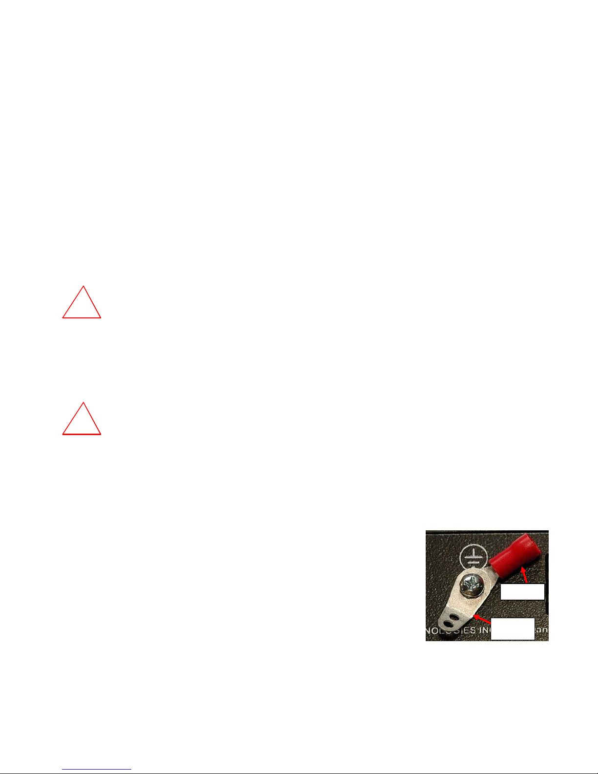
GROUNDING
This product is equipped with grounding hardware to prevent interference from sources of
electrical noise that could interfere with the normal operation of the VOPEX or damage it.
Use either the crimp-on lug or solder terminal to secure a properly grounded wire to the
VOPEX.
Crimp-on
Solder
terminal
i
Page 3

TABLE OF CONTENTS
Introduction......................................................................................................................................................................1
Materials..........................................................................................................................................................................1
Features and Functions...................................................................................................................................................2
Limitations .......................................................................................................................................................................4
Preparation for Installation ..............................................................................................................................................4
VOPEX Installation..........................................................................................................................................................5
VOPEX-C5USBVA-x ...................................................................................................................................................5
Local Device Connections...........................................................................................................................................6
Remote Unit Installation..................................................................................................................................................7
ST-C5USBVUA-R-1000...............................................................................................................................................7
Connect the CATx cable .................................................................................................................................................8
Plug-in and Boot Up........................................................................................................................................................9
Configuration and Command Mode..............................................................................................................................10
Command Mode........................................................................................................................................................10
Adjust Brightness....................................................................................................................................................10
Automatic Video Quality Adjustment......................................................................................................................10
Fine Video Quality Adjustment ...............................................................................................................................11
General Video Quality Adjustment ......................................................................................................................11
Color Skew Adjustment.......................................................................................................................................11
Test Patterns .......................................................................................................................................................11
Update DDC............................................................................................................................................................11
Toggle MAC Mode..................................................................................................................................................12
Exit Command Mode ..............................................................................................................................................12
Firmware Upgrade Procedure.......................................................................................................................................13
Requirements ............................................................................................................................................................13
Prepare to Upgrade the Firmware.............................................................................................................................14
Upgrade Procedures..................................................................................................................................................15
Start the Bootloader................................................................................................................................................15
Upgrade the Local Controller Firmware..................................................................................................................15
Upgrade the Local Port Controller Firmware..........................................................................................................16
Upgrade the Remote Controller Firmware..............................................................................................................16
Technical Specifications................................................................................................................................................18
Interconnection Cable Wiring Method...........................................................................................................................19
RJ45 Connector Wiring..............................................................................................................................................19
Troubleshooting.............................................................................................................................................................19
Warranty Information.....................................................................................................................................................20
TABLE OF FIGURES
Figure 1- Connecting the VOPEX to a PC.........................................................................................................................................5
Figure 3- Connect local devices as needed.......................................................................................................................................6
Figure 4- Connect the Extended Components to the ST-C5USBVUA-R-1000 Remote Unit.............................................................7
Figure 5- Connect a CATx cable between the VOPEX and each Remote Unit .................................................................................8
Figure 6- Connect the AC adapter to a VOPEX.................................................................................................................................9
Figure 7- Connect the AC adapter to an XTENDEX Remote Unit .....................................................................................................9
Figure 8- MAC Mode LED................................................................................................................................................................12
Figure 9- Connect PC for firmware upgrade....................................................................................................................................14
Figure 10- View looking into RJ45 female........................................................................................................................................19
ii
Page 4
NTI VOPEX SERIES CAT5 USB KVM SPLITTER/EXTENDER
INTRODUCTION
The VOPEX
®
VGA USB KVM Splitter with built-in USB hub extends one USB computer (PC, SUN, MAC) to up to four users
(four USB keyboards, mice and VGA monitors) connected to XTENDEX Series Remote Units.
Options:
For support for up to eight users, order VOPEX-C5USBVA-8.
For support for USB touch screen monitor, CAC card reader, or interactive whiteboard, add a “U” to the part number (order
VOPEX-C5USBVUA-x (x= 4 or 8))
Remote video and audio devices can be located as much as 1000 feet away from the source via Category 5e/6/6A/7
unshielded or shielded (see chart on page 18) twisted-pair cable. The VOPEX can optionally supply video and audio to
devices located near the source and provides support for any USB 2.0 full speed device connected to its ports.
The VOPEX Series VGA Splitter/Extender is extremely simple to install and has been thoroughly tested to insure reli able
performance. Through the use of CATx unshielded twisted-pair cable it is possible to economically increase the flexibility of
a computer system. Here are some of the features and ways this can benefit the user:
• Allows the placement of monitors, USB devices and self-powered stereo speakers/amplifiers in different remote
locations where only these parts are needed.
• Provides crisp and clear resolution up to 1080p
• Video quality adjustment is automatic for varying lengths of CATx cable
• Digital transmission of audio signals reduces any loss in quality.
• Audio can be broadcast to self-powered stereo speakers at each remote location and to the local unit.
MATERIALS
Materials Included with this kit:
¾ VOPEX-C5USBV(U)A-x (x= 4 or 8 for number of CATx ports)
¾ 120VAC or 240VAC at 50 or 60Hz-5VDC/2.0A AC Adapter (4 Port) or 3.0A AC Adapter (8 Port)
¾ VEXT-3 3 Foot VGA Male-Female Video Cable
¾ USB2-AB-1M-5T 1 Meter USB Male Type A-Male Type B cable
¾ SA-3-MM 3 Foot 3.5mm male-male stereo plug -stereo plug cable
¾ DB9F-RJ45F- Adapter (CT6182) (VOPEX-C5USBVU(A)-4/-8 models only)
¾ 5 Foot CAT5 Patch Cable (VOPEX-C5USBVU(A)-4/-8 models only)
¾ CD with a pdf file of this manual
Additional materials not supplied but are required:
¾ CAT5/5e/6 Solid UTP/STP EIA/TIA 568B cable(s) terminated with RJ45 connectors wired straight thru- pin 1 to pin 1,
etc. (see page 19 for proper EIA/TIA 568B wiring method) (see also limitations on page 4 and resolution chart on page
18)
¾ One or more of the following XTENDEX Remote Units:
Compatible Splitter Remote Unit Supported Features
ST-C5USBV-R-1000S USB KVM VOPEX-C5USBVA-x
ST-C5USBVA-R-1000S USB KVM + Audio
VOPEX-C5USBVUA-x
Contact your nearest NTI distributor or NTI directly for all of your KVM needs at 800-RGB-TECH (800-742-8324) in US &
Canada or 330-562-7070 (Worldwide) or at our website at www.networktechinc.com
assistance.
ST-C5USBVU-R-1000S USB KVM + Additional USB Port +
Firmware Upgradable
ST-C5USBVUA-R-1000S USB KVM + Additional USB Port +
Audio+Firmware Upgradable
and we will be happy to be of
1
Page 5
NTI VOPEX SERIES CAT5 USB KVM SPLITTER/EXTENDER
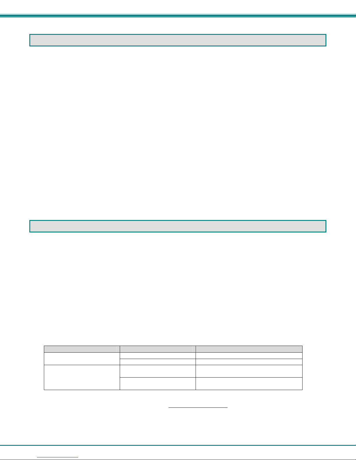
FEATURES AND FUNCTIONS
VOPEX
#
LABEL CONNECTOR DESCRIPTION
1 Video In
2 USB CPU
3 Audio In
4 Video Out
5 USB Devices
6 Audio Out
7 RS232 Firmware
Upgrade
8 5VDC 2A
9 Pwr
10 Ground
11 CATx Output 1-4
15HD male video
connector
USB Type B female for connecting a USB cable between the VOPEX and the PC
3.5mm Stereo jack for connecting to stereo audio source
15HD female video
connector
USB Type A female for connecting any USB 2.0 full speed devices
3.5mm Stereo jack for connecting self-powered stereo speakers
RJ45 connector for connecting RS232 communication cable between the VOPEX and
Power Jack connection jack for the AC adapter (“3A” for 8-port model)
Green LED Illuminates when power has been applied to the VOPEX
Crimp and solder
terminals
RJ45 connector for connecting the CATx cable between the VOPEX and Remote units
for connecting a VGA cable between the VOPEX and the PC
for connecting the local display device
the RS232 port of a terminal (VOPEX-C5USBVUA-4/-8 only)
for connecting to earth ground
2
Page 6
NTI VOPEX SERIES CAT5 USB KVM SPLITTER/EXTENDER
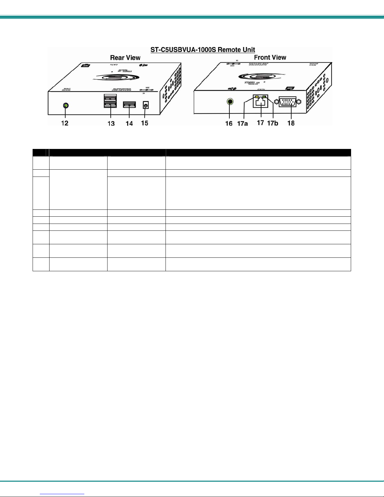
XTENDEX Remote Unit (Sold Separately)
#
LABEL CONNECTOR DESCRIPTION
12 MAC Mode
SUPPORTED USB
13
DEVICES
14
15 5VDC 3A
16 Audio Out
17 CATx
17a Yellow LED -- traffic indicator- illuminates when there is communication between
17b Green LED -- power indicator- illuminates when power has been supplied to the
18 Video Out
Green LED for visual indication that the Local Unit is configure d for connection to a
MAC CPU
USB Type A female for connection of remote user USB device(s)
USB Type A female extra USB port present in ST-C5USBVUA-R-1000S and ST-
C5USBVU-R-1000S remotes only.
When present, support is also present for touch screen monitor, CAC
reader, or SMART Board™ (for connection to any one of the 3 USB
Type A ports).
Power Jack for connecting AC adapter to Remote Unit
3.5mm Stereo Jack for remote connection of self-powered stereo speakers
RJ45 Female for connecting the CATx cable between the VOPEX and Remote unit
the VOPEX and Remote Units.
unit
15HD female video
connector
for connecting the remote display device
3
Page 7
NTI VOPEX SERIES CAT5 USB KVM SPLITTER/EXTENDER
LIMITATIONS
• The audio input of the VOPEX-C5USBVA-4 / -8 is compatible with the following standard CPU audio outputs:
• Line out - typically lime green in color
• Speaker out- typically orange in color
• Headphone out- typically located on the CD-ROM
• The audio outputs of the VOPEX and the XTENDEX Remote Unit are compatible with self-powered stereo speakers.
PREPARATION FOR INSTALLATION
• Locations should be chosen for the monitors and speakers that also have space to connect the VOPEX and XTENDEX
Remote Units within the distance provided by the cables. If extension cables are needed, contact NTI for the cables
required.
• The CATx cables must be run to the locations where the VOPEX and XTENDEX Remote Units will be connected. Be
careful to route the cables away from any sources of magnetic fields or electrical interference that might reduce the
quality of the video signal (i.e. AC motors, welding equipment, etc.). NOTE: If CAT5 cable is already installed in the
wall and there are RJ45 wall outlets, it will be necessary to obtain male-to-male straight through connection cables long
enough to reach from the wall outlets to the connection locations of the VOPEX and XTENDEX Remote Units.
• A properly grounded, polarized, and preferably surge-protected 120V or 240V electrical outlet (de pending on the AC
adapter being used) must be installed close enough to the connection location of the VOPEX and XTENDEX Remote
Units, monitors, stereo speakers, and CPU to plug them into.
• All cables should be installed in such a way that they do not cause stress on their connections to the equipment.
Extended lengths of cable hanging from a connection may interfere with the quality of that connection. Secure cables
as needed to minimize this.
• Properly shut down and disconnect the power from all devices to be separated. If other equipment is involved whose
connections are being interrupted, be sure to refer to the instruction manuals for that equipment for proper disconnection
and re-connection procedures before proceeding.
Note: CAT5 connection cable used between NTI XTENDEX Series Local and Remote or any XTENDEX Series
products should not be run underground, outdoors or between buildings.
!
WARNING: Outdoor or underground runs of CAT5 cable could be dangerous and will void the warranty.
4
Page 8

NTI VOPEX SERIES CAT5 USB KVM SPLITTER/EXTENDER
VOPEX INSTALLATION
VOPEX-C5USBVUA-x
1. Make connections between the VOPEX and the CPU. (See Fig. 1.)
a) Connect the VEXT-3 (supplied) between the 15HD connector on the CPU and the 15HD male connector
marked "Video In" on the VOPEX.
b) Plug one 3.5mm stereo plug end of the SA-3-MM cable (supplied) into the 3.5mm female audio
connector marked "line out", "spkr", or "headphones" on the audio source.
Notes:
If all 3 connectors are available, use the connector marked "line out".
The "line out" connector is typically lime green and may be marked with this symbol
The "spkr" connector is typically orange, and may be marked with this symbol
The "headphones" connector may be marked with this symbol
c) Connect the other 3.5mm stereo plug end of the SA-3-MM cable into the 3.5mm female stereo
audio connector marked "Audio In" on the VOPEX.
e) Connect the USB2-AB-1M cable (supplied) between a USB Type A port on the CPU and the “USB CPU”
USB Type B connector on the VOPEX.
Figure 1- Connecting the VOPEX to a PC
5
Page 9

NTI VOPEX SERIES CAT5 USB KVM SPLITTER/EXTENDER
Local Device Connections
If a VGA monitor and USB devices are to be located close to the VOPEX, connection ports are provided on the VOPEX
to support them.
The connections labeled “USB DEVICES” will support the connection of any USB 2.0 Low Speed or Full Speed rated
devices, not just the keyboard and mouse shown below.
An “AUDIO OUT” jack is provided for the connection of self-powered stereo speakers.
Figure 2- Connect local devices as needed
6
Page 10

NTI VOPEX SERIES CAT5 USB KVM SPLITTER/EXTENDER
REMOTE UNIT INSTALLATION
ST-C5USBVUA-R-1000
1. Position a ST-C5USBVUA-R-1000 Remote Unit such that the CATx cable, the monitor cable, and speaker
cable can each reach the Remote Unit comfortably.
2. Connect the remote user's monitor cab le to the female 15HD video connector on the Remote Unit.
3. Connect the remote user's self-powered speakers (where applicable) to the 3.5mm female stereo connector on
the Remote Unit.
4. If the monitor is a USB-connected touchscreen type, connect the USB cable from the monitor to one of the
USB Type A connectors labeled “Supported USB Devices” on the Remote Unit. (Supported on XTENDEX
Remote model ST-C5USBVUA-R-1000 or ST-C5USBVU-R-1000 only)
Note: The VOPEX must be model VOPEX-C5USBVUA-x to use an XTENDEX Remote Unit with touchscreen
monitor, CAC reader, or interactive whiteboard support.
Figure 3- Connect the Extended Components to the ST-C5USBVUA-R-1000 Remote Unit
7
Page 11

NTI VOPEX SERIES CAT5 USB KVM SPLITTER/EXTENDER
CONNECT THE CATX CABLE
Make sure the CATx cable has been installed in accordance with the “Preparation for Installation” instructions on page 4.
Connect a CATx cable to one of the ports marked “CATx Output” on the VOPEX. Connect the other end of that cable
to the “Cat x” port on a Remote Unit. When properly inserted the CATx cable end should snap into place.
Repeat for each Remote Unit installed.
!
WARNING: Never connect the VOPEX to an Ethernet card, Ethernet router, hub or switch or other
Ethernet RJ45 connector of an Ethernet device. Damage to devices connected to the Ethernet may result.
Figure 4- Connect a CATx cable between the VOPEX and each Remote Unit
8
Page 12

NTI VOPEX SERIES CAT5 USB KVM SPLITTER/EXTENDER
PLUG-IN AND BOOT UP
Proper Power-Up Sequence: 1) Power ON XTENDEX Remote Unit
2) Power ON VOPEX
3) Power ON CPU (See details below)
1. Plug the power cord from each monitor and the power supply for each audio device into a power outlet.
2. Connect the 5VDC 3.0A AC adapter power connector to the power port on the XTENDEX Remote Unit.
Plug the AC adapter into a power outlet. The green LED on the XTENDEX should illuminate, indicating that a proper
3.
power connection has been made. (See Figure 5)
Figure 5- Connect the AC adapter to an XTENDEX Remote Unit
Connect the 5VDC 2.0A AC adapter power connector to the power port on the VOPEX (5VDC 3.0A on 8-port model).
4.
Plug the AC adapter into a power outlet. The green LED on the VOPEX should illuminate, indicating that a proper
5.
power connection has been made. (See Figure 6)
The 8-port model includes an AC
adapter rated 5VDC 3.0A. .
Figure 6- Connect the AC adapter to a VOPEX
6. Turn ON the CPU, stereo speakers, and monitors. They should react as if they were directly connected to each other.
Note: The yellow LED on the RJ45 connector of each XTENDEX Remote Unit will illuminate anytime data traffic is
passing between the VOPEX and the XTENDEX, indicating proper CATX cable connection and communication.
(See Figure 4)
9
Page 13

NTI VOPEX SERIES CAT5 USB KVM SPLITTER/EXTENDER
CONFIGURATION AND COMMAND MODE
Command Mode
All models are enabled with a Command Mode feature to perform the following:
Command Mode can be enabled by pressing two keys at the Remote Unit keyboard
<RIGHT SHIFT>. Press <Esc> at any time to exit Command Mode.
The three keyboard LEDs (NumLock, CapsLock, and ScrollLock) will blink at the same time to indic ate entrance into
Command Mode.
Commands available in Command Mode:
Key press Effect Extra Control
<Up Arrow> increases brightness
<Down Arrow> decreases brightness
<A> forces Auto Video Quality
<Left Arrow> Decreases fine video adjustment
<Right Arrow> Increases fine video adjustment
<R> Enable Red Color Skew Adjustment
<G> Enable Green Color Skew
<B> Enable Blue Color Skew Adjustment
<D> Enter DDC Update Mode Use <Left Arrow> + <Right
<V> Returns to General Video Quality
<M>
<W>
<Esc> Exits Command Mode
¾ fine adjustment of the general video quality
¾ fine adjustment of color skew (alignment of red, green, and blue signals on the monitor)
¾ update DDC information between the monitor(s) and CPU
¾ toggle between MAC mode and non-MAC mode
at the same time; <LEFT SHIFT> +
Adjustment
Use <Left Arrow> or <Right
Mode
Adjustment Mode
Mode
Adjustment Mode from DDC Update
Mode or Color Skew Adjustment
Modes
Enable MAC Mode
Disable MAC Mode
Arrow> to adjust
Use <Left Arrow> or <Right
Arrow> to adjust
Use <Left Arrow> or <Right
Arrow> to adjust
Arrow> to update (press
simultaneously)
Adjust Brightness
The brightness of the extended image can be increased or decreased by pressing the <Up Arrow> or <Down Arrow>
(respectively) while in Command Mode. This adjustment is in addition to any adjustments made possible by controls on
your monitor.
Automatic Video Quality Adjustment
Video quality is broken down into “general video quality” for brightness and sharpness of the images, and “color skew” for
how the colors align with each other on the monitor. Both general video quality and color skew adjustments are done
automatically any time the XTENDEX is powered ON or if the CATx cable is disconnected and then reconnected. These
adjustments can also be forced by pressing the <A> key while in Command Mode.
The automatic video adjustments are calibrated for unshielded twisted pair cable. For shielded cable fine adjustment may be
necessary and this can be done from keyboard keys using Command Mode. Video Quality Adjustment settings are
automatically stored in the XTENDEX. Settings will be restored each time the XTENDEX is powered-ON. Test patterns for
color skew adjustment are provided on the CD.
Note: If the cable is changed after making manual video adjustments, the XTENDEX will restore these settings to
factory default and fine adjustments with the new cable may be necessary.
10
Page 14

NTI VOPEX SERIES CAT5 USB KVM SPLITTER/EXTENDER
Fine Video Quality Adjustment
General Video Quality Adjustment
Command Mode opens into General Video Quality Adjustment mode. To fine tune the general video quality, press the
<Left Arrow> or <Right Arrow> keys until the desired improvement in the display has been achieved.
Color Skew Adjustment
If a specific color appears to be skewed and is in need of fine adjustment, the user can switch to Red, Green, or Blue Skew
Adjustment mode by pressing <R>, <G> or <B> respectively. The keyboard LEDs will identify the mode as indicated in the
table below. Press the < Left Arrow> or <Right Arrow> keys until the desired improvement in the color alignment has
been achieved. Press <V> to return to General Video Quality Adjustment mode.
Test Patterns
To verify the need for and effect of color skew adjustment using a test pattern specifically designed for your display setting,
browse the CD this manual was found on and click on the “test-pattern-nXm.pdf” file that matches your current video
resolution. Follow the instructions above to make adjustments as needed.
Note: For additional quality adjustment, it may be necessary to adjust the brightness and contrast settings of the
monitor.
Keyboard LEDs Indications:
Adjustment Mode NumLock CapsLock ScrollLock
Command Mode ON Blink Blink Blink
Red Skew Blink Solid Solid
Green Skew Solid Blink Solid
Blue Skew Solid Solid Blink
DDC Update Off Solid Off
Command Mode OFF Normal state Normal state Normal state
Update DDC
DDC information allows the CPU to automatically select the optimal resolution for your monitor. The procedure to update
DDC information (below) must be performed only once at initial setup through Command Mode (provided the monitor is not
changed). Both the Local and Remote Units must be powered in order to update the DDC information. The DDC
information will be based on the monitors connected to the Remote Unit and locally at the VOPEX.
To update DDC information (from Command Mode);
1. press <D> to enter DDC Update mode. (See chart above for LED indications.)
2. press the < Left Arrow> + <Right Arrow> keys simultaneously to cause DDC information to be updated
3. press <V> to return to General Video Quality Adjustment mode.
4. press <Esc> to exit Command Mode
5. Restart the CPU.
Note: It is recommended that the monitors connected to the Remote Units and VOPEX be able to support the same
resolutions.
Attention: Some graphics cards will not send a video signal to the monitor until it has received the DDC information from the
monitor. In this case, the monitor may not display anything until the DDC information is read. This may occur if the monitor
is being connected to the XTENDEX for the first time. The DDC information must be updated in the XTENDEX to achieve
video using the procedure outlined above.
If the monitor is changed to a different model than was initially installed, the update procedure must be repeated through
Command Mode.
DDC Mixing
To mix DDC information from multiple monitors (providing a table of resolutions that are common to each connected
monitor), perform the update procedure above at each remote connected to a monitor that is to be added to the mix. This
will provide DDC information to the CPU that is common to all connected monitors. If the resulting list of resolution options
at the CPU is undesirable, to clear it and start over, power cycle the VOPEX and repeat the update procedure at the remote
for each desired monitor.
Note: The DDC information from the local monitor (connected to the VOPEX) will be added to the mix if it is
connected during the update procedure.
11
Page 15

NTI VOPEX SERIES CAT5 USB KVM SPLITTER/EXTENDER
Toggle MAC Mode
MAC Mode enables the user to connect the VOPEX to a MAC CPU. MAC Mode configures the VOPEX for passing mouse
information to the MAC CPU. This is useful when the user wants to use mouse drivers provided by the mouse vendor, which
allows the use of programmable functions for each mouse button. The XTENDEX can be configured whenever necessar y.
Use the following procedure for each XTENDEX Remote Unit that requires the use of MAC Mode for the mouse connected
to it.
In the default setting (non-MAC Mode), the VOPEX is configured for connection to a SUN or Windows CPU. To toggle
between non-MAC Mode and MAC Mode, press <M> while in Command Mode. The “MAC Mode” LED on the Remote Unit
will illuminate when the VOPEX is in MAC Mode.
NOTE: When the port is connected to a PC or SUN CPU, MAC Mode (and the MAC Mode LED) should be OFF.
To do this;
1. Enter Command Mode. (Simultaneously press the left and right <Shift> keys on the keyboard connected to the
Remote Unit
2. If a MAC CPU is connected, press the <M> key. The keyboard LEDs will momentarily flash and the “MAC” LED on
the Remote Unit will illuminate to indicate MAC Mode is ON.
To reconnect the VOPEX to a SUN or Windows CPU (the default setting), press the <W> key and the “MAC” LED will go
OFF.
. The keyboard LEDs will illuminate. )
Figure 7- MAC Mode LED
Exit Command Mode
Press the <Esc> key to exit Command Mode and return to normal operation. All keyboard LEDs will return to current
keyboard LED state.
FYI: Video quality will be limited by several factors. Some factors include the quality and type of CAT5 cable
being used, the length of cable run, the quality of the monitor, the resolution setting of the monitor, and the quality
of the video card used in the video source. If the desired level of image clarity cannot be achieved by making the
adjustments described in this section, consider the following possible adjustments that can be made:
• Improve the quality of cable used -CAT5,5e,or 6 (CAT5e unshielded (UTP) cable will provide the
best performance)
• Use unshielded cable (UTP) instead of shielded cable (STP)
• Shorten the length of the cable between the remote and local
• Reduce the resolution setting on the monitor used
• Use a higher quality video card in the video source
12
Page 16

NTI VOPEX SERIES CAT5 USB KVM SPLITTER/EXTENDER
FIRMWARE UPGRADE PROCEDURE
This procedure describes how to upgrade the firmware in this VOPEX (Models VOPEX-C5USBVUA-4/-8 only). If you are
not certain whether this VOPEX has the most up-to-date firmware available, simply download the latest version and follow
the upgrade procedure. All versions of firmware can be downloaded from http://www.networktechinc.com/download/d-kvm-
splitter-cat5.html .
The VOPEX and XTENDEX combination includes 3 different firmware files, two in the VOPEX (Local) and one in the
XTENDEX (Remote):
1. Local Controlle r – the Local Controller will be upgraded with a binary file named vc5usbv-csx-x.bin. (where x-x is the
rev number)
2. Local Port Controller – the Local Port Controller will be upgraded with a hex file named vc5usbv-cpx-x.hex.
3. Remote Controller – the Remo te Controller will be upgraded with a bin file named c5usbvu-rcsx-x.bin.
The VOPEX firmware has a bootloader which can be used for firmw are upgrades. The bootloader resides in a protected
area of Flash memory, so that if the upgrade fails for any reason, the bootloader will still b e available to be used to reprogram the entire unit.
Upgrades are made to the Local Controller, Local Port Controller, or Remote Controller separately. Not all Controller
firmware is updated with each revision, however it is highly recommended that if you upgrade one piec e of firmware, you
upgrade each controller segment to make sure your VOPEX and XTENDEX Remote Unit(s) are all at current versions.
Requirements
¾ CAT5 Patch Cable (supplied)
¾ RJ45-DB9 Adapter (supplied)
¾ Computer with a Terminal Console (for example, HyperTerminal in Windows, or any similar program able to send files
using Xmodem protocol)
¾ Firmware files for the VOPEX on the computer with the Terminal Console.
13
Page 17

NTI VOPEX SERIES CAT5 USB KVM SPLITTER/EXTENDER
Prepare to Upgrade the Firmware
Models VOPEX-C5USBVUA-4/-8 only
With the power to the PC and VOPEX OFF, connect a PC to the VOPEX using the supplied 5 foot patch cable and 9DB-toRJ45 adapter. Connect the patch cable to the “RS232 FIRMWARE UPGRADE” port on the VOPEX, attach the supplied
9DB-to-RJ45 adapter to the patch cable, and connect the 9DB adapter to an available serial COM port on the PC.
Figure 8- Connect PC for firmware upgrade
2. Power ON the computer only. Open the terminal console and apply the following settings to the terminal console for the
port connected to the VOPEX:
Baud rate: 57600
Data bits: 8
Parity: none
Stop bits: 1
Flow control: none
14
Page 18

NTI VOPEX SERIES CAT5 USB KVM SPLITTER/EXTENDER
Upgrade Procedures
Start the Bootloader
In the HyperTerminal window on the attached computer, press and hold the <Tab> key and power ON the VOPEX.
The following message (or one similar) will be displayed on the screen:
ST-C5-USBVA Bootloader
Revision: 1.1
Date: 2010/01/11 15:40:16
Copyright (C) Network Technologies Inc
Press <H> for help…
>
Release the <Tab> key.
The “>” prom pt indicates that the bootloader is waiting for commands. T he available commands are compos ed by sending
one ASCII character. To send a command to the bootloader, type the key in the terminal window that corresponds to the
desired command. The available commands, listed below, can be viewed by typing <h> or <H> (the Help command) from the
keyboard.
Note: Commands can be typed using upper or lower case letters.
Local Bootloader List of Commands:
h, H - Display list of commands
x, X - Exit Bootloader
u, U - Upgrade Local controller firmware
p, P - Upgrade Local port controller firmware
r, R - Upgrade Remote controller firmware
s, S - Read Checksum of the Local port controller firmware
Upgrade the Local Controller Firmware
The Local controller firmware comes as a file in binary format and has the extension .bin. (i.e. filename.bin). To upgrade the
Local controller to this file, press <u> from Terminal window. The following message should appear on the screen:
Erasing flash memory…
Memory successfully erased
Send .bin file using Xmodem protocol..
At this point the binary file vc5usbv-csx-x.bin must be sent. To do this, from HyperTerminal:
1. go to “Transfer” menu in the Menu Bar of the HyperTerminal window
2. click the item “Send File …”
3. in the dialog box which pops up on the screen, browse for the file to be sent and select it
4. select “Xmodem” from the Protocol drop-down menu
5. press “Send” button
The transmission will start shortly. Wait until the transmission is finished. There will be some pauses during transmission,
since the processor writes blocks of 4KB.
When the transmission is complete, the HyperTerminal window should show the following status message and retur n to the
menu prompt:
Device successfully programmed!
>
To exit from the bootloader, press <x>.
15
Page 19

NTI VOPEX SERIES CAT5 USB KVM SPLITTER/EXTENDER
Upgrade the Local Port Controller Firmware
The Local port controller firmware comes as a file in Intel Hex format and has the extension .hex (i.e. filename.hex). To
upgrade any of Local Port controller with this firmware, press <p> from the terminal window. The following message should
appear on the screen:
Send .hex file using XModem protocol...
At this point, the hex format file vc5usbvu-cpx-x.hex has to be sent, using HyperTerminal and the same procedure as
before. When the transmission is done, the following message will be shown in the HyperTerminal window:
File transfer OK!
Please, type <A> to program chip or <X> to exit
To program the chip, just press <a>).
The following message will be shown on the screen (it may take about 12 seconds to program):
Programming device, please wait...
Device ID: 0x001E
Device successfully programmed!
To exit from the bootloader, press <x>.
Note: The Local port
will include both of the current Local and Remote controller firmware versions, but will only include the Local port
controller firmware if it has changed.
controller firmware will rarely, if ever, need to be updated. The firmware download package
Upgrade the Remote Controller Firmware
Note: To upgrade the Remote Controller firmware, the Remote Unit must be connected to port #4 on the VOPEX.
The Remote controller firmware comes as a file in binary format and has the extension .bin. (i.e. filename.bin). To upgrade
the Remote controller to this file, press <r> from Terminal window. The following message should appear on the screen:
The Local Unit bootloader will now pass control
to the Remote Unit bootloader
Please, check that the Remote Unit is powered off
Please, type <Y> to continue or <X> to cancel
If you type <Y> to continue you get the following message:
To enter into Remote Unit bootloader, power on the unit
while keeping the <TAB> key pressed
Remote Bootloader List of Commands:
h, H - Display list of commands
x, X - Exit Bootloader
r, R - Upgrade Remote controller firmware
16
Page 20

NTI VOPEX SERIES CAT5 USB KVM SPLITTER/EXTENDER
To proceed to upgrade the Remote controller, press <r> from Terminal window. The following message should appe ar on
the screen:
Erasing flash memory…
Memory successfully erased
Send .bin file using Xmodem protocol..
At this point the binary file c5usbvu-rcsx-x.bin must be sent. To do this, from HyperTerminal:
1. go to “Transfer” menu in the Menu Bar of the HyperTerminal window
2. click the item “Send File …”
3. in the dialog box which pops up on the screen, browse for the file to be sent and select it
4. select “Xmodem” from the Protocol drop-down menu
5. press “Send” button
The transmission will start shortly. Wait until the transmission is finished. There will be some pauses during transmission,
since the processor writes blocks of 4KB.
When the transmission is complete, the HyperTerminal window should show the following status message and retur n to the
menu prompt:
Device successfully programmed!
>
To exit from the bootloader, press <x>.
17
Page 21

NTI VOPEX SERIES CAT5 USB KVM SPLITTER/EXTENDER
TECHNICAL SPECIFICATIONS
Characteristic
Video Compatibility VGA,SVGA, XGA, SXGA,UXGA
Video Quality Adjustment
Sync Types Supported Separate and composite TTL Level
Maximum Resolution See tables below
Video Connectors HD15 male to CPU
Video Coupling DC
Video Maximum I/O Levels 1.45Vp-p
Input / Output Impedance 75 Ohms
Input Horizontal Frequency Range 15kHz to 130 k Hz
Input Vertical Frequency Range 30 Hz to 150 Hz
Audio
Audio Connectors 3.5mm female stereo audio connectors
Signal Type Line Level, stereo, unbalanced
Audio Frequency Response 20Hz to 20Khz, + 1dB
Signal-to-noise ratio >76 dBA
Total Harmonic Distortion and Noise 0.017%,F=20-20KHz, RL=2K Ohm, Vout=1 Vrms
Stereo Crosstalk -70 dB @ 1kHz
Audio Maximum I/O Levels 3.1Vp-p
Output Impedance Max 2K Ohms, unbalanced
General
Interconnect Cable CAT5/5e/6 Solid UTP/STP EIA/TIA 568B wiring w/ male RJ45 connectors
VOPEX-C5USBV(U)A-x
4-Port Power
8-Port Power
Remote Unit Power
AC Adapter Power Connector 1.3X3.5mm connector, center positive
Storage temperature -20 to 140°F (-30 to 60°C)
Operating Temperature Range 32°F to 100°F (0°C to 38°C)
VOPEX Size (In.) WxDxH
VOPEX-C5USBV(U)A-4
VOPEX-C5USBV(U)A-8
XTENDEX Remote Unit Size (In.) WxDxH 5.05x3.1x1.235
Enclosure type Electro-galvanized steel black powder coated
Distances and Maximum Supported Resolutions for CAT5, CAT5e and CAT6 Cables
Unshielded Twisted Pair (UTP) Resolutions Shielded Twisted Pair (STP) Resolutions
UTP CABLE DISTANCE (feet) RESOLUTION STP CABLE DISTANCE (feet) RESOLUTION
CAT5/5e 1000 1920x1200 at 60Hz CAT5/5e 800** 1920x1200 at 60Hz
CAT5/5e/6 800* 1920x1440 at 60Hz CAT5/5e 600 1920x1440 at 60Hz
CAT5/5e/6 600 2048x1536 at 60Hz CAT5/5e 400 2048x1536 at 60Hz
*The performance of CAT6 unshielded, is not guaranteed
beyond 800 feet.
Note: Results may vary depending on cable and/or display quality
Automatic, for up to 1000 feet of CAT5 cable, with manual override
(fine video quality adjustment can only be performed manually at the Remote
Unit)
HD15 female to monitor
120V or 240V at 50 or 60Hz-5VDC/2.0A via AC Adapter
120V or 240V at 50 or 60Hz-5VDC/3.0A via AC Adapter
120V or 240V at 50 or 60Hz-5VDC/3.0A via AC Adapter
7.35x5.0x1.09
7.35x5.0x1.7
CAT6 400** 1280x1024 at 60Hz
CAT6 300 1600x1200 at 60Hz
CAT6 200 2048x1536 at 60Hz
**The performance of CAT5 and CAT5e shielded cable is not
guaranteed beyond 800 feet (400 feet for CAT6 shielded).
18
Page 22

NTI VOPEX SERIES CAT5 USB KVM SPLITTER/EXTENDER
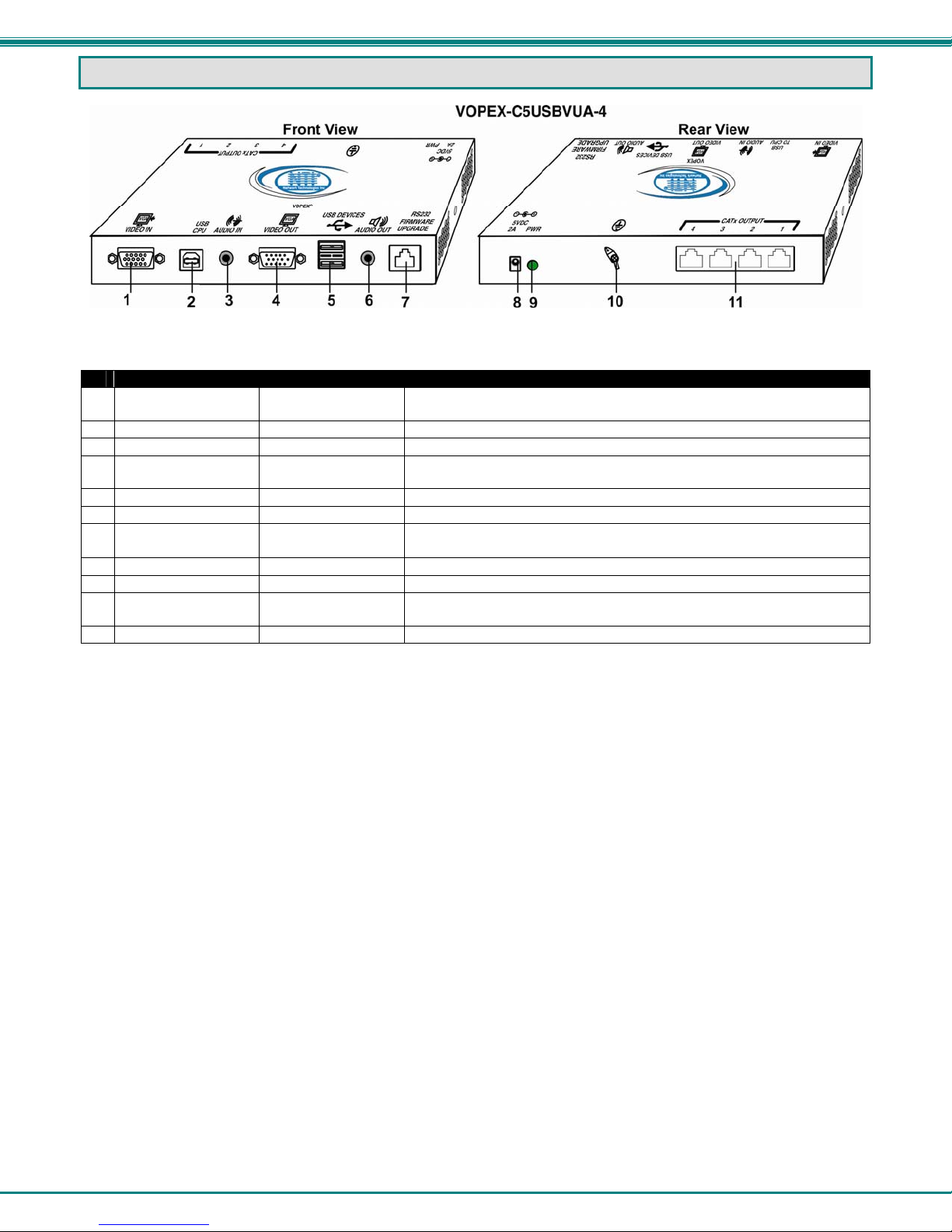
INTERCONNECTION CABLE WIRING METHOD
The connection cable between the VOPEX and each XTENDEX Remote Unit is terminated with RJ45 connectors and must
be wired according to the EIA/TIA 568B industry standard. Wiring is as per the table and drawing below.
Pair 3
RJ45 Connector Wiring
1 White/Orange 2 T
2 Orange 2 R
3 White/Green 3 T
4 Blue 1 R
5 White/Blue 1 T
6 Green 3 R
7 White/Brown 4 T
8 Brown 4 R
Figure 9- View looking into RJ45 female
Note: CATx connection cable used between NTI VOPEX and the XTENDEX Series Remote or any XTENDEX Series
products should not be run underground, outdoors or between buildings.
!
WARNING: Outdoor or underground runs of CATx cable could be dangerous and will void the warranty.
Pin Wire Color Pair Function
Pair 2 Pair 1
T
T
R
R
3
1
2
4
+
-
+
-
Pair 4
T
5
+
R
R
T
8
6
7
-
+
-
TROUBLESHOOTING
Each and every piece of every product produced by Network Technologies Inc is 100% tested to exacting specifications.
We make every effort to insure trouble-free installation and operation of our products. If problems are experienced while
installing this product, please look over the troubleshooting chart below to see if perhaps we can answer any questions that
arise. If the answer is not found in the chart, a solution may be found in the knowledgebase on our website at
http://information.networktechinc.com/jive/kbindex.jspa
(330) 562-7070 and we will be happy to assist in any way we can.
Problem Cause Solution
VOPEX power LED does
not illuminate
XTENDEX power LED
does not illuminate
No video on
monitor/display
• Power supply is not connected or
plugged-in.
• VOPEX is not powered ON
• CATx cable not connected
• One or more video cables is loose
or disconnected.
• No power to the VOPEX or the
XTENDEX Remote Unit.
• Video Cable was not attached
when video source was poweredup.
• CATx cable is not connected.
• Cable is too long for the selected
resolution
or please call us directly at (800) 742-8324 (800-RGB-TECH) or
• Make sure the outlet is live and the AC adapter is
plugged-in. Make sure DC plug / AC line cord is fully
connected.
• Make sure VOPEX is ON
• Check that the CATx cable is snapped-in properly at
each end of the cable
• Check all video cable connections
• Make sure power LEDs are illuminated for local and
remote. If not, see solution for problem above.
• With all the cables properly connected, cycle the power
to the video source.
• Check cable connections. Make sure they are snapped-
in properly and reboot.
• Check Distances and Resolutions chart on page 14.
19
Page 23

NTI VOPEX SERIES CAT5 USB KVM SPLITTER/EXTENDER
Problem Cause Solution
Monitor sometimes goes
blank for an instant or the
video is noisy
No audio
USB doesn’t does not
work after power cycling
VOPEX or hot plugging
the USB on the VOPEX
• Electrical power system is very
noisy, particularly the ground.
• The CATx cable is not properly
connected.
• Cable is too long for the selected
resolution
• Audio cable is not properly
plugged in
• Speakers are not plugged in
• CATx cable is not properly
connected
The CPU may take a minute or more
to re-recognize the VOPEX after a hot
plug or power cycle
• Make sure the interconnection cable is not near any
power lines.
• Check cable connections. Make sure they are snappedin properly.
• Check Distances and Resolutions chart on page 14.
• Check all cable connections
• Verify speakers are powered (if applicable)
• Check CATx cable connections
Wait at least a minute or two to give the CPU opportunity to
refresh its connection with the VOPEX.
WARRANTY INFORMATION
The warranty period on this product (parts and labor) is two (2) years from the date of purchase. Please contact Network
Technologies Inc at (800) 742-8324 (800-RGB-TECH) or (330) 562-7070 or visit our website at
http://www.networktechinc.com for information regarding repairs and/or returns. A return authorization number is required
for all repairs/returns.
Manual 208 Rev. 11/20/14
20
 Loading...