

Page 1
NTI
R
NETWORK
TECHNOLOGIES
INCORPORATED
1275 Danner Dr
Aurora, OH 44202
www.nti1.com
Tel:330-562-7070
Fax:330-562-1999
VOPEX-3V-SE-2 (Video Splitter/Switch)
INSTALLATION/USER GUIDE
MAN004 REV DATE 4/30/02
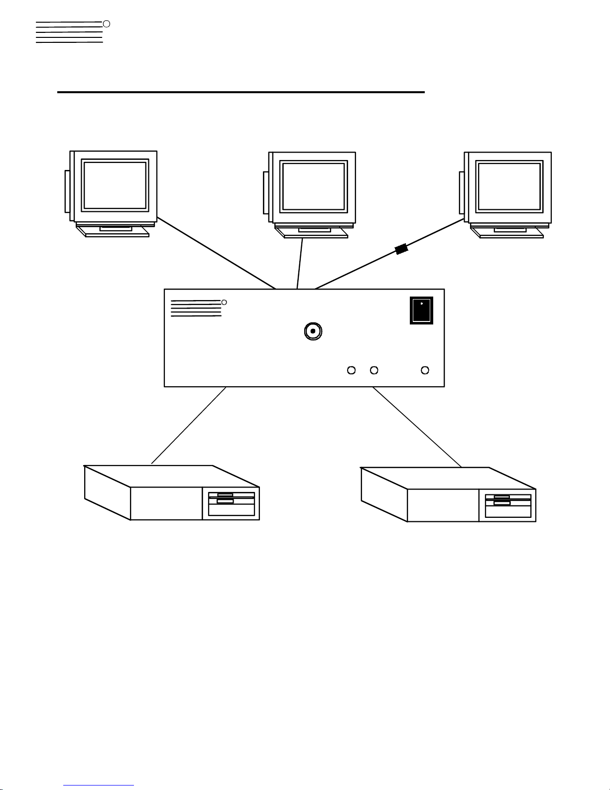
VGA
Multi-Scan
Monitor
Monitor Cable
(existing)
R
NETWORK
TECHNOLOGIES
NTI
VOPEX-3V-SE-2
VEXT-6
INCORPORATED
VOPEX-3V-SE-2
VGA
Multi-Scan
Monitor
Monitor Cable
(existing)
SELECT
VGA
Multi-Scan
Monitor
Monitor Cable
(existing)
Extension Cable
VEXT-xx (optional)
PWR21
VEXT-6
CPU CPU
1
Page 2
INTRODUCTION
The VOPEX-3V-SE-2 Video Splitter/Switch enables three monitors to display video from two CPUs. Two monitors will be
dedicated to specific CPUs, and the third monitor can be switched to display video from either CPU. An external switch will
determine which CPU is connected to the third monitor.
The VOPEX-3V-SE-2 Video Splitter/Switch is compatible with:
• VGA monitors
• SVGA monitors
• XGA monitors
• P80 video and sync timing data.
Materials Supplied with this kit:
• 1- VOPEX-3V-SE-2 Video Splitter/Switch
Materials Required but not Supplied:
• 2- VEXT-6 6 foot video cable
INSTALLATION
1. Turn off power to the computers and monitors.
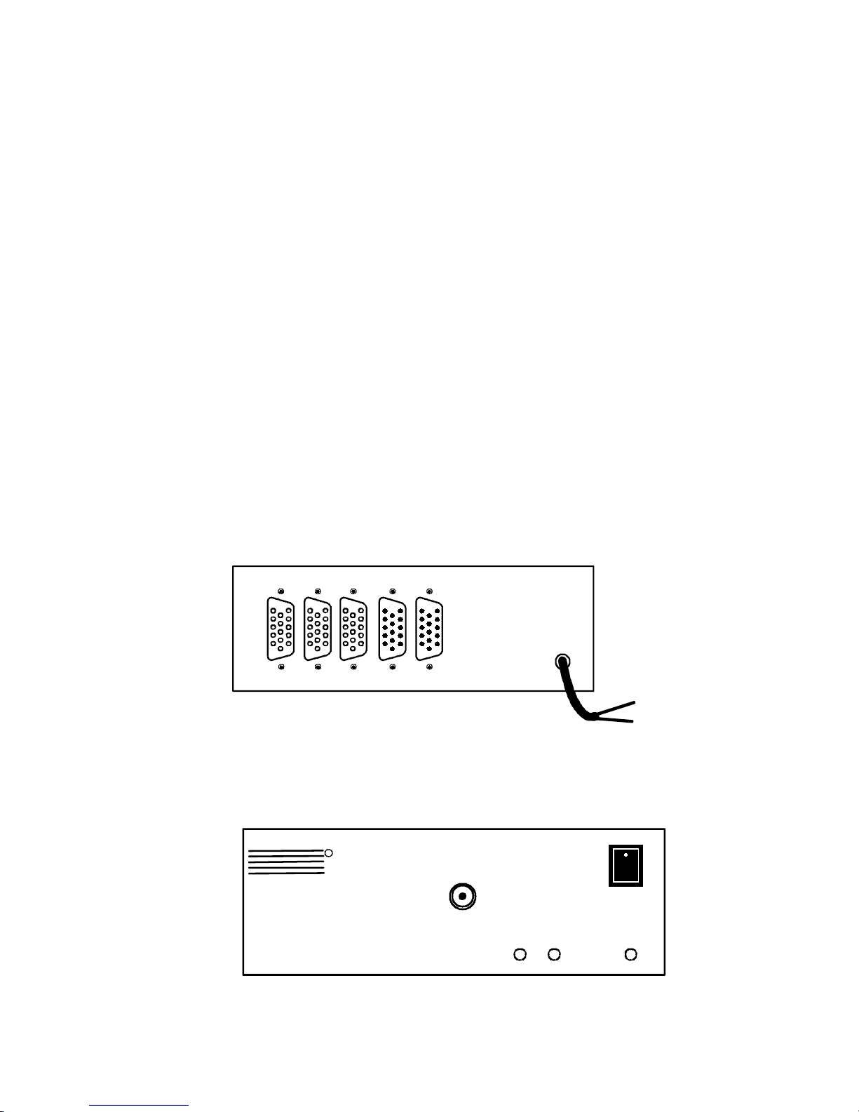
2. Disconnect the monitor cable from a CPU and reconnect it to VID 1 on the rear of the VOPEX-3V-SE-2 (see Fig.1). A monitor
must be connected to VID 1 for the VOPEX-3V-SE-2 to work properly.
3. Connect the male end of a VEXT-6 cable to that CPU's 15HD female video output connector.
4. Connect the female end of this VEXT-6 cable to the 15HD male CPU 1 connector on the VOPEX-3V-SE-2.
5. Disconnect the monitor cable at another CPU and reconnect it to the 15HD female VID 2 connector.
6. Connect the male end of another VEXT-6 cable to the second CPU's 15HD female video output connector.
7. Connect the female end of the second VEXT-6 cable to the 15HD male CPU 2 connector on the VOPEX-3V-SE-2.
8. A third monitor may be plugged into the 15HD female VID 3 connector on the VOPEX-3V-SE-2.
9. Power up the VOPEX-3V-SE-2 Video Splitter/Switch.
10. Power up the CPUs and monitors.
VID 3
VID 2 VID 1 CPU 2 CPU 1
REAR VIEW OF VOPEX-3V-SE-2
Fig. 1
Brown= +24VDC
Yellow= GND
24VDC
Brown
(+24VDC)
Green/Yellow
(Ground)
CONTROL
The monitor connected to VID 3 can either display the video signal from the CPU connected to CPU 1 or from the CPU connected
to CPU 2. Selection between the two CPUs is controlled by an external, 2-position, toggle switch (not included) that connects to a
BNC connector labeled "SELECT" on the VOPEX-3V-SE-2 Video Splitter/Switch (see Fig. 2). The states of the toggle switch are
connected (signal = 24V) and disconnected (signal = 0V).
R
NETWORK
TECHNOLOGIES
NTI
INCORPORATED
SELECT
VOPEX-3V-SE-2
0V= CPU 1
24V= CPU 2
PWR21
FRONT VIEW OF VOPEX-3V-SE-2
Fig. 2
2
Page 3

The external toggle switch should operate as follows:
Switch Signal VID 3
Disconnected 0V Connected to CPU 1
Connected +24VDC Connected to CPU 2
The shell of the BNC connector is ground and signal stem is the toggle line (see Fig. 3).
SELECT
Toggle Line
(24VDC)
Ground
BNC Connector
Fig. 3
The switch is to be powered by an external +24VDC connected to the bare end of the line cord. The line cord wires are color
coded as follows:
Wire Color Signal
Brown +24VDC
Green/Yellow Ground
STATUS LEDS
There are three LEDs on the front of the VOPEX-3V-SE-2 Video Splitter/Switch (see Fig. 2). The LEDs will indicate the state of
the VOPEX-3V-SE-2 Video Splitter/Switch.
LED INDICATION
PWR VOPEX-3V-SE-2 has been supplied with the proper po wer supply (+24VDC)
1 VID 3 has been connected to CPU 1
2 VID 3 has been connected to CPU 2
BLOCK DIAGRAM
VOPEX-3V-SE-2
Monitor 1will always display the
video from User 1
Monitor 2 will always display
the video from User 2
Monitor 3 can be switched
between User 1 and User 2 via
an external 2-position switch.
VID 1 VID 2 VID 3 CPU 1 CPU 2
15HD-F 15HD-F 15HD-F 15HD-M 15HD-M
VIDEO BUFFERS
RGB, HVRGB, HV
VIDEO
BUFFER
RGB, HV
VIDEO MUX
WHEN TOGGLE = 0,
VID3 = CPU1
WHEN TOGGLE =1,
VID3 = CPU2
TOGGLE
WHEN "SELECT" = 24VDC,
TOGGLE =1
WHEN "SELECT" = 0VDC,
TOGGLE =0
RGB, HVRGB, HV
VIDEO
BUFFER
"SELECT"
BNC CONNECTOR
EXTERNAL
2-POSITION SWIT CH
3
Page 4

TROUBLESHOOTING
PROBLEM SOLUTION
No Video • Make sure the power LED is illuminated on the VOPEX-3V-SE-2
• Check cable connections, make sure they are secure
Poor Resolution • Make sure monitors are fully plugged into connectors of VOPEX-3V-SE-2
WARRANTY INFORMATION
The warranty period on this product (parts and labor) is one (1) year from date of purchase. Please contact Network Technologies
at (800) 742-8324 or 330-562-7070 for information regarding repairs and/or returns. A return authorization number is required for
all repairs/returns.
COPYRIGHT
Copyright 2002 by Network Technologies Inc. All rights reserved. No part of this publication may be reproduced, stored in a
retrieval system, or transmitted in any form or by any means, electronic, mechanical, photocopying, recording, or otherwise,
without the prior written consent of Network Technologies Inc, 1275 Danner Drive • Aurora, OH 44202.
CHANGES
The material in this guide is for information only and is subject to change without notice. Network Technologies Inc reserved the
right to make changes in the product design without reservation and without notification to its users.
MODEL NO: VOPEX-3V-SE-2
SERIAL NO: ____________________
DATE:_____________________
INSPECTED BY: _____________________
4
 Loading...