

Page 1
V
OPEX®Series
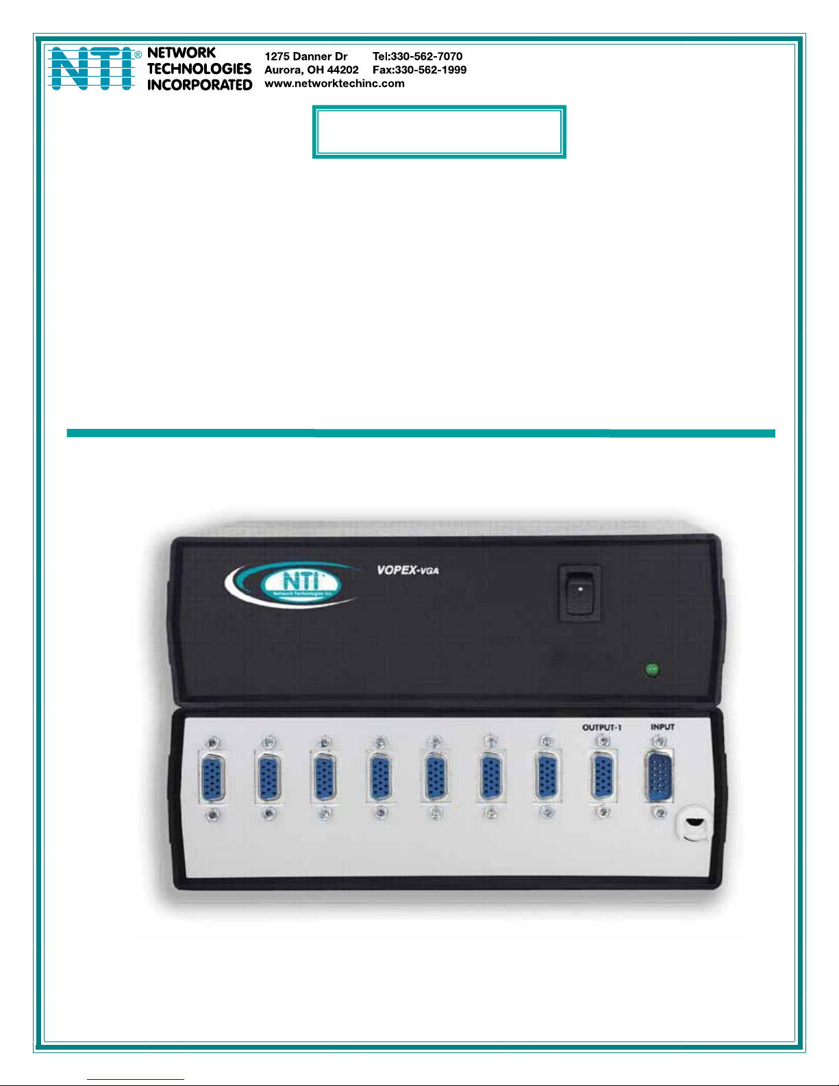
VOPEX-2V/4V/8V/16V-H
VOPEX-2VA/4VA/8VA-H
VIDEO AND AUDIO/VIDEO SPLITTER
Installation and Operation Manual
MAN003 Rev 7/11/07
Page 2

TRADEMARK
VOPEX is a registered trademark of Network Technologies Inc in the U.S. and other countries.
COPYRIGHT
Copyright 2003, 2007 by Network Technologies Inc. All rights reserved. No part of this publication may be reproduced, stored in
a retrieval system, or transmitted in any form or by any means, electronic, mechanical, photocopying, recording, or otherwise,
without the prior written consent of Network Technologies Inc, 1275 Danner Drive, Aurora, OH 44202.
CHANGES
The material in this guide is for information only and is subject to change without notice. Network Technologies Inc reserves the
right to make changes in the product design without reservation and without notification to its users.
MAN003 Rev 7/11/07
Page 3
INTRODUCTION
The VOPEX-2V/4V/8V/16V-H video port splitter enables two, four, eight, or sixteen monitors to be driven from the same video
port.
• These units have a bandwidth of 150 MHz enabling them to support high resolution video – up to 1900x1200 with no
degradation.
• These units are compatible with VGA, SVGA, and XGA monitors.
• The VOPEX 2V/4V/8V/16V-H is also DDC compatible on OUTPUT-1 and only on OUTPUT-1.
• VOPEX-2V/4V/8V/16V-H video port splitters can be cascaded to drive up to 100 monitors by interconnecting multiple units
(see page 3 for illustration).
Option:
VOPEX with UL Listed power supply- to order add -UL to model number (VOPEX-2V/4V/8V/16V-H-UL)
VOPEX with audio support added (non-UL)- to order add A to the model number (VOPEX-2VA-H)(2, 4, and 8 port models only)
Materials Supplied:
VOPEX-2V/4V/8V/16V-H -Video Port Splitter
VEXT-THN-3 3-Foot Video Interface Cable
SA-3-MM 3-Foot Stereo Audio Interface Cable (models with audio support only)
Optional Materials
VEXT-THN-xx Video Extension Cable- available up to 250 feet in length (500 feet for resolutions of 800 x 600)
SA-xx-MM Audio Extension Cable- available in 3, 6, 10, 15, 25, 35, 50, and 100 foot lengths
Where xx is the length of the cable in feet
O U T P U T 1
"
!#
'&$
%
#
" !
R E A R V I E W O F V O P E X - 2 V - H
O U T P U T 2
"
!#
'&$
%
#
" !
(not supplied):
I N P U T
O U T P U T 1
"
!#
'&$
#
" !
%
O U T P U T 2
"
!#
'&$
%
#
" !
R E A R V I E W O F V O P E X - 2 V - H - U L
I N P U T
1 7 V D C
A d a p t e r
A D A P T E R
U L L I S T E D
AUDIO
OUT 2
NETWORK TECHNOLOG IES IN C
AUDIO
OUT 1
Tel:330-562-70701275 Danner Dr, Aurora, OH 44202 www.networktechinc.com
REAR VIEW OF VOPEX-2VA-H
AUDIO
IN
INPUTOUTPUT 1OUTPUT 2
1
Page 4

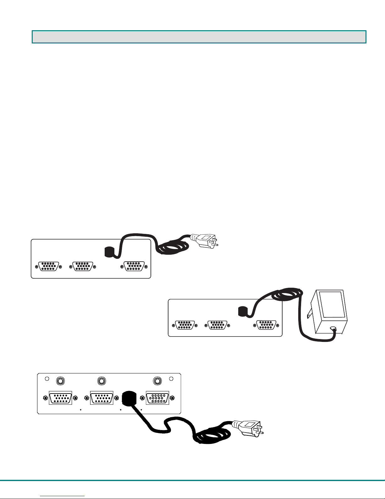
INSTALLATION
1. Turn OFF power to CPU and monitor(s).
2. Disconnect the monitor cable at the CPU and reconnect it to OUTPUT 1 on the rear of the VOPEX. OUTPUT 1 must be
connected to a monitor for the unit to operate properly. It is labeled as such (see Fig. 1).
Note: If a monitor with DDC support will be used, it must be connected to OUTPUT-1. All other monitors must support
the highest video resolution supported by the DDC monitor connected to OUTPUT-1.
3. Install the 15HD male end of the NTI-supplied video interface cable into the CPU’s video output connector.
4. Install the 15HD female end of this cable into the INPUT connector of the VOPEX.
5. Additional monitors may be plugged into the remaining OUTPUT(s) as required.
6. Plug in VOPEX power cord and turn unit ON.
Note: VOPEX-xV-H-UL model does not have power switch. Just plug in AC adapter to power up.
7. Turn ON power to CPU and monitor(s).
Extension Cable
Existing Cable
15HD male
Video Connector
OUTPUT 1 OUTPUT 2
REAR VIEW OF VOPEX-2V-H
Figure 1- Connect VOPEX to monitors and CPU
VEXT-THN--xx (optional)
INPUT
42351
10 986
15 14 13 12 11
VEXT-THN-3 (supplied)
CPU
7
15HD female
Video Connector
2
Page 5

AUDIO SUPPORT
Models with audio support (i.e. VOPEX-2VA-H) can additionally be connected to an audio source. A 3.5mm jack is provided for
connection to the audio source using the 3 foot audio cable (provided). Outputs are provided for connection of self-powered
stereo speakers, headphones, and/or ear buds. Additional sets of stereo speakers, headphones, and/or ear buds can be
connected when multiple VOPEX splitters are cascaded.
Notes:
The audio port on a CPU may be marked "line out", "spkr", or "headphones". If all 3 jacks are
available, use the jack marked "line out".
The "line out" jack is typically lime green and may be marked with this symbol
The "spkr" jack is typically orange, and may be marked with this symbol
The "headphones" jack may be marked with this symbol
3.5mm Stereo Plug
Audio Port
ONE WILL BE MA RKE D "lin e
out" ,"spkr", "headphones"
OR WITH THIS SYMBOL
Figure 2- Connect VOPEX with audio support
Self-powered
Stereo Speakers
3.5mm Stereo Jack
line
out
AUDIO
OUT 2
NETWORK TECHNOLOGIES INC Tel:330-562-70701275 Danner Dr, Aurora, OH 44202 www.networktechinc.com
AUDIO
OUT 1
AUDIO
IN
INPUTOUTPUT 1OUTPUT 2
Rear View of VOPEX-2VA-H
Rear View of a CPU
3.5mm Stereo
Plug
SA-3-MM (supplied)
Headphones
3.5mm Stereo
Plug
3
Page 6

CASCADING
Up to 100 monitors can be driven using a single CPU by cascading multiple VOPEX splitters as shown in Fig. 2. Other than
additional VOPEX splitters, the only additional hardware required are VEXT-THN-xx cables with lengths sufficient to reach each of
the monitors to be connected and for connecting the VOPEX splitters. (For cascading speakers using VOPEXs with audio
support, additional SA-xx-MM cables will be required (see page 1)).
Note: If a DDC monitor is to be used in a cascaded application, it must be connected to OUTPUT 1 of the VOPEX
connected to the master VOPEX at OUTPUT 1 (labeled "SLAVE #1 in Fig. 2).
#2-8
#1
#2-8
Extension Cable
VEXT-THN-xx (optional)
Existing
Cable
Extension Cable
VEXT-THN-xx (optional)
O
O
O
O
O
U
U
T
T
P
P
U
U
T
T
8
7
NETWORK TECHNOLOGIES
U
U
T
T
P
P
U
U
T
T
6
5
INC
O
U
U
T
T
P
P
U
U
T
T
4
3
REAR VIEW OF VOPEX-8V-H REAR VIEW OF VOPEX-8V-H
O
O
U
U
T
P
U
T
2
Tel:330-562-70701275 Danner Dr, Aurora, OH 44202 www.networktechinc.com
I
T
N
P
P
U
U
T
T
1
O
O
O
O
O
U
U
U
T
T
P
P
U
U
T
T
8
7
NETWORK
T
P
U
T
6
TECHNO LOGIE S IN C
U
T
P
U
T
5
O
U
U
T
T
P
P
U
U
T
T
4
3
O
O
U
U
T
T
P
P
U
U
T
T
1
2
Tel:330-562-70701275 Danner Dr, Aurora, OH 44202 www.networktechinc.com
SLAVE #1SLAVE #2
VEXT-THN-xx
VEXT-THN-xx
O
U
T
P
U
T
8
O
O
U
U
T
T
P
P
U
U
T
T
6
7
NETWORK TECHNOLOGIES
REAR VIEW OF VOPEX-8V-H
O
U
T
P
U
T
5
INC
MASTER
O
U
T
P
U
T
4
O
O
U
T
P
U
T
3
O
U
U
T
T
P
P
U
U
T
T
2
1
Tel:330-562-70701275 Danner Dr, Aurora, OH 44202 www.networktechinc.com
I
N
P
U
T
VEXT-THN-3 (supplied)
CPU
Figure 3- VOPEX-8V-H splitters in cascaded application
#1
(DDC
MONITOR)
Existing Cable
I
N
P
U
T
4
Page 7

Self-powered
Stereo Speakers
Existing Cable
O
U
T
P
U
T
8
NETWORK TECHNOLOGI ES INC Tel:330-562-70701275 Danner Dr, Aurora, OH 44202 www.networktechinc.com
654 3
78
O
O
U
U
T
T
P
P
U
U
T
T
6
7
AUDIO OUT
O
O
U
U
T
T
P
P
U
U
T
T
4
5
REAR VIEW OF VOPEX-8VA-H REAR VIEW OF VOPEX-8VA-H
SLAVE #2 SLAVE #1
O
U
T
P
U
T
3
21
O
O
U
U
T
T
P
P
U
U
T
T
1
2
AUDIO IN
I
N
P
U
T
SA-xx-MM
O
U
T
P
U
T
3
21
O
O
U
U
T
T
P
P
U
U
T
T
1
2
654 3
78
O
O
O
U
T
P
U
T
8
NETWORK TECHNOLOGIESINC Tel:330-562-70701275 Danner Dr, Aurora, OH 44202 www.networktechinc.com
U
U
T
T
P
P
U
U
T
T
6
7
O
U
T
P
U
T
5
AUDIO OUT
O
U
T
P
U
T
4
O
U
T
P
U
T
8
NETWORK TECHNOLO GIES INC Tel:330-562-70701275 Danner Dr, Aurora , OH 44202 www.networktechinc.com
6543
78
O
O
U
U
T
T
P
P
U
U
T
T
6
7
O
U
T
P
U
T
5
AUDIO OUT
O
U
T
P
U
T
4
REAR VIEW OF VOPEX-8VA-H
MASTER
O
U
T
P
U
T
3
21
O
O
U
U
T
T
P
P
U
U
T
T
2
1
AUDIO IN
I
N
P
U
T
SA-3-MM
(supplied)
Figure 4- VOPEX-8VA-H splitters with cascading speakers
AUDIO IN
I
N
P
U
T
SA-xx-MM
CPU
5
Page 8

V
TECHNICAL SPECIFICATIONS
IDEO INPUT/OUTPUT SIGNALS
PIN # SIGNAL PIN # SIGNAL
1 RED 9 NC
2 GREEN 10 GND
3 BLUE 11 ID0
4 ID2 12 DDC DAT
5 GND 13 HS
6 GND 14 VS
7 GND 15 DDC CLK
8 GND
VIdeo
Output Connectors 15HD female
Input Connector 15HD male
Compatibility VGA, SVGA, XGA
Resolution 1900x1200 at 50 feet
Bandwidth 150MHz
Max. Input level
Input impedance 75 Ohms
Sync support Separate and Composite TTL level sync and Sync On Green.
Sync input frequency ranges Horizontal: 15 kHz to 130 kHz.
Audio
Connector Stereo Audio Jack, 3.5mm
Input Impedance 10K
Load Powered speakers, headphones (32 ohm)
Audio Frequency Range 20Hz - 20KHz +/-1dB
THD,% 0.012
Crosstalk -82dB
General
Operating Temperature
Storage Temperature
Operating and Storage Relative
Humidity
Power 110 or 220VAC at 50 or 60Hz
Regulatory approval RoHS
1600x1200 at 100 feet
1.45Vp-p
Vertical: 30 Hz to 150 Hz.
32°F to 100°F (0°C to 38°C)
-20°F to 140°F (-30°C to 60°C)
17 to 90% non-condensing RH.
Mating Face of a 15HD Male
42351
10
98
15 14
13 12 11
3.5mm Stereo Jack
(side view)
RING (RIGHT)
TIP (LEFT)
SLEEVE (GND)
67
(FRONT)
6
Page 9

TROUBLESHOOTING
PROBLEM SOLUTION
No Video
Poor Resolution
• Turn ON power to splitter
• Make sure cable connections are secure
• Make sure monitor is plugged into OUTPUT 1 on rear panel of splitter
• Make sure monitor supports the maximum resolution supported by the
DDC monitor on OUTPUT-1
WARRANTY INFORMATION
The warranty period on this product (parts and labor) is two (2) years from date of purchase. Please contact Network
Technologies Inc at (800) 742-8324 (800-RGB-TECH) in the U.S. and Canada or 330-562-7070 (worldwide) for information
regarding repairs and/or returns. A return authorization number is required for all repairs/returns.
SERIAL NO: ______________________
DATE: ______________________
INSPECTED BY: _____________________
VOPEX-2V-H VOPEX-2VA-H
VOPEX-4V-H VOPEX-4VA-H
VOPEX-8V-H VOPEX-8VA-H
VOPEX-16V-H
MAN003 Rev 7/11/07
7
 Loading...