

Page 1

®
XTENDEX
Series
USB-C5-200
200 Foot USB Extender
Installation and Operation Manual
Front and Rear View of USB-C5-200 Remote Unit
MAN026 Rev Date 7/10/2017
Page 2
TRADEMARK
XTENDEX is a registered trademark of Network Technologies Inc in the U.S. and other countries.
COPYRIGHT
Copyright © 2010, 2017 by Network Technologies Inc. All rights reserved. No part of this publication may be reproduced, stored
in a retrieval system, or transmitted, in any form or by any means, electronic, mechanical, photocopying, recording, or otherwise,
without the prior written consent of Network Technologies Inc, 1275 Danner Drive, Aurora, Ohio 44202.
CHANGES
The material in this guide is for information only and is subject to change without notice. Network Technologies Inc reserves the
right to make changes in the product design without reservation and without notification to its users.
Note: CAT5e/6/7 connection cable used between NTI XTENDEX Series Local and Remote or any XTENDEX Series
products should not be run underground, outdoors or between buildings.
WARNING: Outdoor or underground runs of CATx cable could be dangerous and will void the warranty.
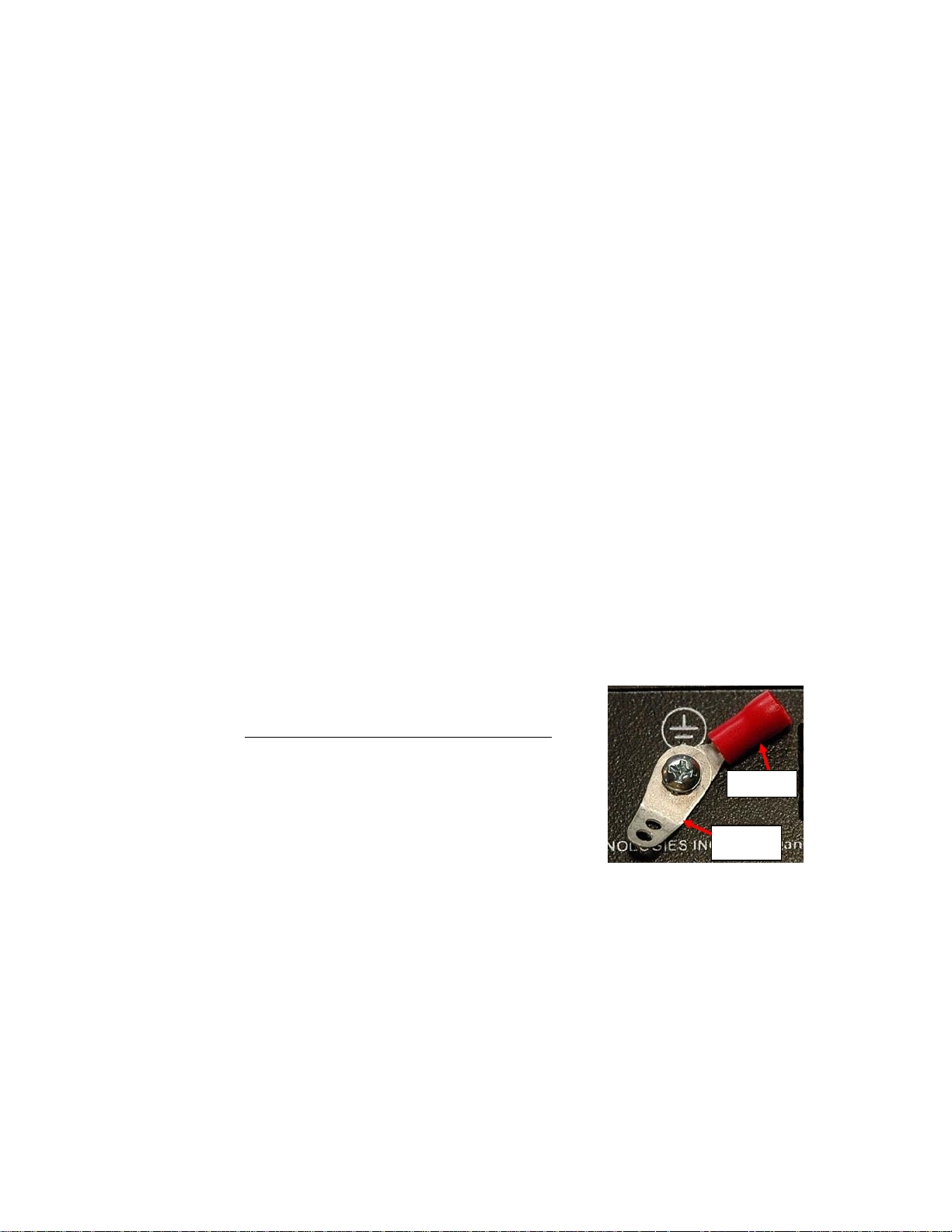
GROUNDING
This product is equipped with grounding hardware to prevent interference from
sources of electrical noise that could interfere with the normal operation of the
XTENDEX or damage it. Use either the crimp-on lug or solder terminal
to
secure a properly grounded wire to the XTENDEX.
Crimp-on
Solder
i
Page 3

TABLE OF CONTENTS
Introduction...................................................................................................................................................................... 1
Materials.......................................................................................................................................................................... 1
Features and Functions................................................................................................................................................... 2
Preparation for Installation ..............................................................................................................................................2
Mounting Brackets........................................................................................................................................................... 3
Installation ....................................................................................................................................................................... 4
Installing The Local Unit ..............................................................................................................................................4
Installing the Remote Unit............................................................................................................................................4
Connect The CATx Cable............................................................................................................................................5
Plug-in and Boot Up..................................................................................................................................................... 5
Interconnection Cable Wiring Method ............................................................................................................................. 6
Technical Specifications.................................................................................................................................................. 6
Troubleshooting............................................................................................................................................................... 7
Warranty Information....................................................................................................................................................... 7
TABLE OF FIGURES
Figure 1- Connect device cable to the Local Unit ..............................................................................................................................4
Figure 2- Connect extended devices to the Remote Unit...................................................................................................................4
Figure 3- Connect CATx cable........................................................................................................................................................... 5
Figure 4- Connect the AC adapter ..................................................................................................................................................... 5
Figure 5- View looking into RJ45 female............................................................................................................................................6
ii
Page 4

NTI XTENDEX USB EXTENDER
INTRODUCTION
The USB Extender extends four USB devices up to 200 feet. Each USB extender consists of a local unit that connects to a
computer and a remote unit that connects to four USB devices.
Supports fully transparent USB connections – able to support all common hardware platforms including PC, SUN and
MAC and their associated peripherals.
Extend devices such as keyboards, mice, printers, game controllers, USB flash drives, touch screen monitors,
whiteboards, etc.
Compliant with USB 1.1 specifications.
Supports low speed and full speed USB devices
Supports Plug-n-Play specification
MATERIALS
Materials Included with this kit:
NTI XTENDEX Local and Remote Unit
1-100VAC to 240VAC at 50 or 60Hz-5VDC/3.0A AC Adapter
1-USB2-AB-1M-5T USB Type A Male-to-USB Type B Male 1 meter cable
Mounting bracket kit (4-MP4869 Universal Extender Brackets, 8- #4-40x3/16” Mach. Screws)
4- 3/16” x 1” Wall Anchors and #6x3/4” Phillips Screws
Materials Not supplied but REQUIRED:
CAT5e Solid/Stranded UTP/STP; CAT6 Solid or Stranded UTP/STP ; CAT6a Solid UTP; CAT7 Solid STP cable(s) terminated
with RJ45 connectors wired straight thru- pin 1 to pin 1, etc. (see page 6 for proper EIA/TIA 568 B wiring method)
Cables can be purchased from Network Technologies Inc by calling (800) 742-8324 (800-RGB-TECH) in the US and Canada or
(330) 562-7070 (worldwide).
1
Page 5
NTI XTENDEX USB EXTENDER
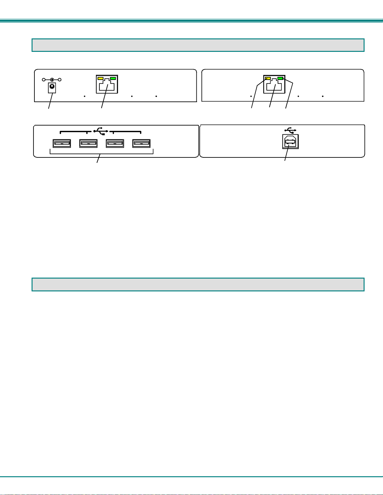
FEATURES AND FUNCTIONS
-
NETWORK TECHNOLOGIES INC Tel:330- 562-70701275 Danner Dr, Aurora, OH 44202 www.networ ktechinc.com
Front View of USB-C5-200 Remote Unit
5VDC
1
3A
+
CAT 5 CAT 5
2
Rear View of USB-C5-200 Remote Unit
123 4
NETWORK TECHNOLOGIES INC Tel:330- 562-70701275 Danner Dr, Aurora, OH 44202 www.networ ktechinc.com
USB DEVICES
3
1. 5VDC- 3.0A- connection jack for the AC adapter
2. CAT 5- RJ45 females- for connecting the CAT 5 cables
2a. Green LED- power indicator- illuminates when power has been supplied to the unit
2b. Yellow LED-traffic indicator- blinks when there is communication between the local and remote units
3. USB- Type A connectors- for connecting extended USB devices
4. CPU USB-Type B connector- for connecting to a USB connector on the CPU for USB device support
Front View of USB-C5-200 Local Unit
2
2b 2a
Rear View of USB-C5-200 Local Unit
CPU USB
4
PREPARATION FOR INSTALLATION
Locations should be chosen for the mice, keyboards, and any other devices where there is also space to connect the Remote
and Local Units within the distance provided by the cables. If extension cables are needed, contact NTI for the cables
required.
The CATx cable must be run to the locations where the Remote and Local Units will be connected. Be careful to route the
cable away from any sources of magnetic fields or electrical interference that might reduce the quality of the extended signals
(i.e. AC motors, welding equipment, etc.).
All cables should be installed in such a way that they do not cause stress on their connections to the equipment. Extended
lengths of cable hanging from a connection may interfere with the quality of that connection. Secure cables as needed to
minimize this.
Properly shut down and disconnect the power from the CPU and devices to be separated. If other equipment is involved
whose connections are being interrupted, be sure to refer to the instruction manuals for that equipment for proper
disconnection and re-connection procedures before proceeding.
Note: CATx connection cable used between NTI XTENDEX Series Local and Remote or any XTENDEX Series products
should not be run underground, outdoors or between buildings.
WARNING: Outdoor or underground runs of CATx cable could be dangerous and will void the warranty.
2
Page 6

NTI XTENDEX USB EXTENDER
MOUNTING BRACKETS
Your XTENDEX has been supplied with mounting brackets and hardware for easy installation should you decide to mount the
XTENDEX to any surface. Assemble the bracket(s) to the Local Unit and/or Remote Unit according to the images below as
desired.
3
Page 7
NTI XTENDEX USB EXTENDER
INSTALLATION
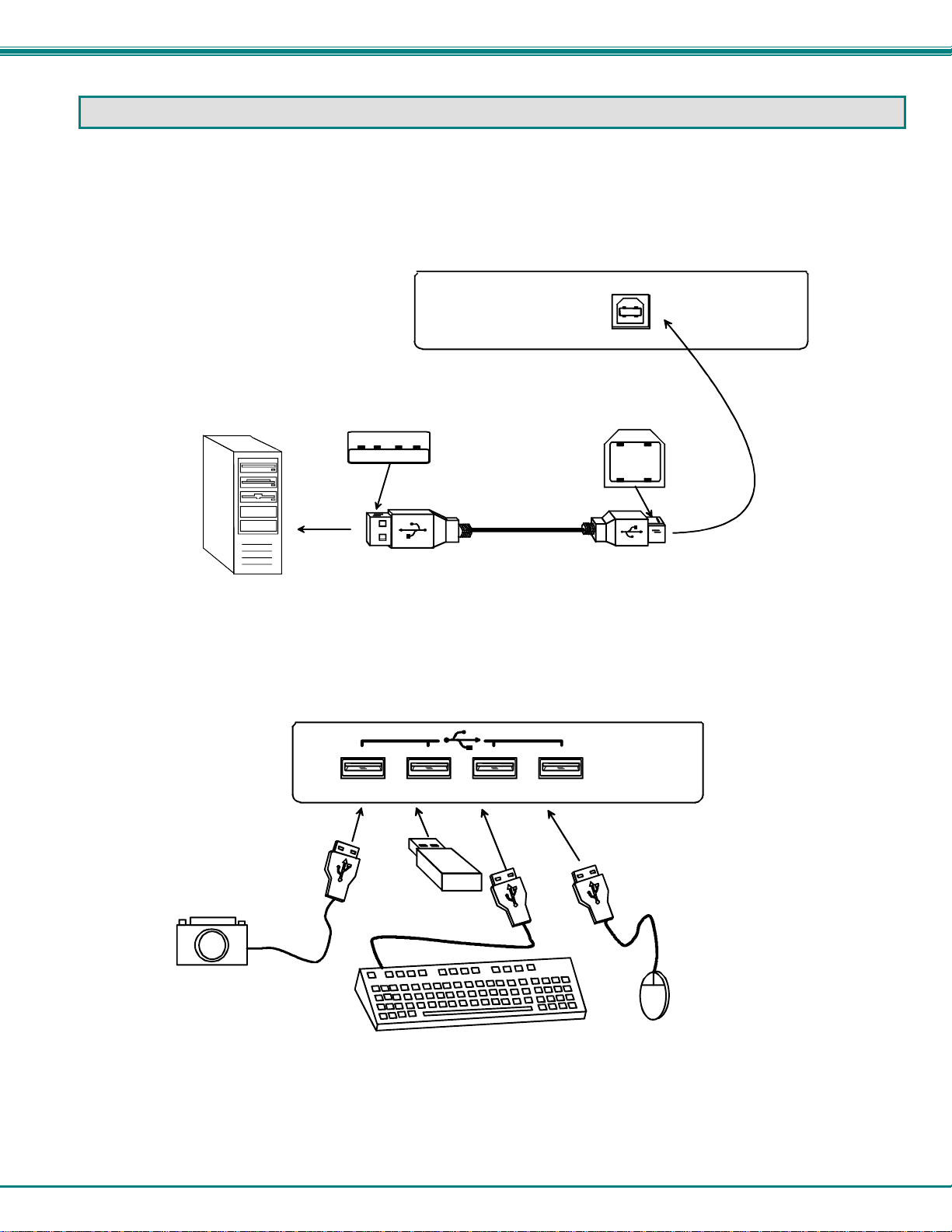
Installing The Local Unit
1. Connect the USB2-AB-1M-5T USB cable from the Local Unit to the back of the CPU. (See Figure 1.)
a) Connect the USB Type A male cable end to a USB Type A female connector on the CPU.
b) Connect the USB Type B male cable end to the USB Type B female connector on the Local Unit.
USB PC, MAC
OR SUN CPU
USB Type A Male
Rear View of USB-C5-200 Local Unit
USB Type B
Male
Figure 1- Connect device cable to the Local Unit
Installing the Remote Unit
Connect cables from the Remote Unit to the extended devices as shown below.
USB CAMERA
Rear View of USB-C5-200 Remote Unit
123 4
USB DEVICES
USB Flash Drive
USB Keyboard
USB MOUSE
Figure 2- Connect extended devices to the Remote Unit
4
Page 8
NTI XTENDEX USB EXTENDER
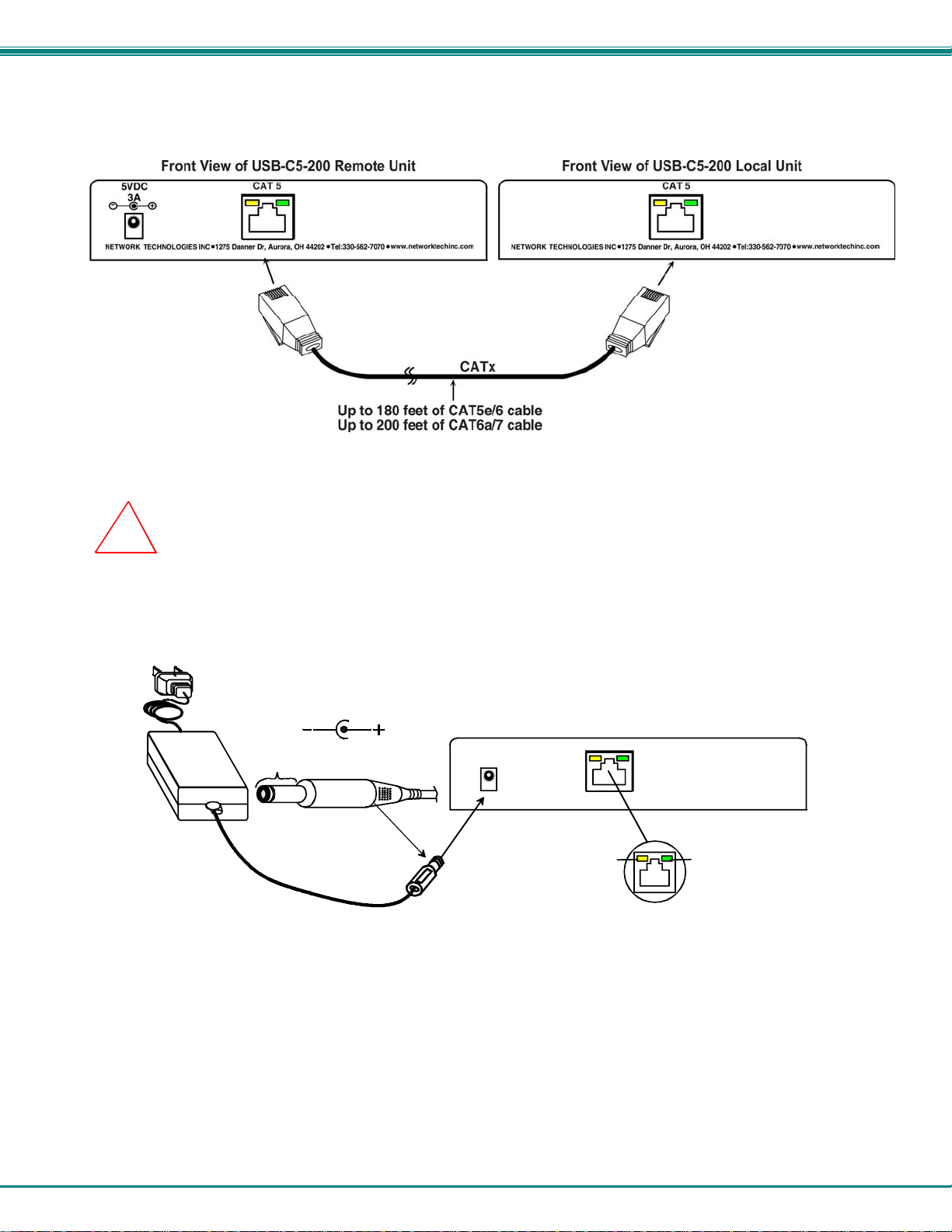
Connect The CATx Cable
Connect the CATx cable between the “Cat 5” port on the Local and Remote Units. (See Figure 3.) When properly inserted
the cable end should snap into place.
Figure 3- Connect CATx cable
!
WARNING: Never connect the XTENDEX to an Ethernet card, Ethernet router, hub or switch or other
Ethernet RJ45 connector of an Ethernet device. Damage to devices connected to the Ethernet may result.
Plug-in and Boot Up
1. Connect the AC adapter power connector to the 5VDC port on the Remote Unit. (The Local Unit is powered by the CPU.)
Plug the AC adapter into a power outlet. The green LED on the RJ45 connector of the Remote Unit should illuminate,
indicating that a proper power connection has been made to it. (See Figure 4.)
5 VDC
AC
ADAPTER
Power Connector
5VDC @ 3.0A OUTPUT
(Outside
barrel)
1.3 mm x 3.5 mm Female
Barrel
(Inside
barrel)
Front View of USB-C5-200 Remote Unit
Yellow Traffic LED
Green Power LED
Figure 4- Connect the AC adapter
2. Turn ON the CPU. The green LED on the RJ45 connector of the Local Unit should illuminate. The CPU and remote devices
should each react as if they were directly connected to each other.
Note: The yellow LED on RJ45 connector will blink anytime data traffic is passing between the Local and Remote Units,
indicating proper CATx cable connection and communication. (See Figure 4)
5
Page 9

NTI XTENDEX USB EXTENDER
INTERCONNECTION CABLE WIRING METHOD
The connection cable between the remote and local is terminated with RJ45 connectors and must be wired according to the
EIA/TIA 568 B industry standard. Wiring is per the table and drawing below.
1 White/Orange 2 T
2 Orange 2 R
3 White/Green 3 T
4 Blue 1 R
5 White/Blue 1 T
6 Green 3 R
7 White/Brown 4 T
8 Brown 4 R
Pin Wire Color Pair Function
Pair 2 Pair 1
T
1
+
Pair 3
Pair 4
T
R
R
T
3
2
4
-
5
+
-
+
R
R
T
8
6
7
+
-
-
Figure 5- View looking into RJ45 female
TECHNICAL SPECIFICATIONS
USB to host CPU USB Type B female
USB to device USB Type A female
USB output power 5V, 1.4A for 4 ports (<500mA per port)
Interconnect Cable CAT5e Solid/Stranded UTP/STP; CAT6 Solid or Stranded UTP/STP ;
Remote Unit Power 100V to 240V at 50 or 60Hz-5VDC/3.0A via AC adapter
Local Unit Power Powered by CPU
Operating temperature
Storage temperature
Operating and Storage Relative Humidity 0 to 90% non-condensing RH
Size (In.) WxDxH 5.1x3.1x1.2
Regulatory Approvals RoHS, CE
Distances for CAT5e, CAT6(a) and CAT7 Cables
Cable USB Device Type Distance (ft)
CAT5e Solid or
Stranded, UTP or STP
CAT6 Solid or
Stranded, UTP or STP
USB 1.1/1.0 180
USB 2.0 150
USB 1.1/1.0 180
USB 2.0 150
CAT6a Solid UTP; CAT7 Solid STP EIA/TIA 568 B wiring
32°F to 122°F (0°C to 50°C)
-20°F to 140°F (-30°C to 60°C)
CAT6a Solid UTP
CAT7 Solid SSTP
USB 1.1/1.0 200
USB 2.0 180
USB 1.1/1.0 200
USB 2.0 180
6
Page 10
NTI XTENDEX USB EXTENDER
TROUBLESHOOTING
Each and every piece of every product produced by Network Technologies Inc is 100% tested to exacting specifications. We
make every effort to insure trouble-free installation and operation of our products. If problems are experienced while installing this
product, please look over the troubleshooting chart below to see if perhaps we can answer any questions that arise. If the
answer is not found in the chart, a solution may be found in the knowledgebase on our website at
http://information.networktechinc.com/jive/kbindex.jspa or please call us directly at (800) 742-8324 (800-RGB-TECH) or
(330) 562-7070 and we will be happy to assist in any way we can.
Problem Cause Solution
Remote or Local Unit
green power LED does not
illuminate
CPU doesn't detect the
keyboard and the mouse
Power supply is not connected or
plugged-in (Remote Unit).
CPU is not powered ON (Local
Unit)
Keyboard cable or mouse cable
are loose
CATx cable is too long
Make sure outlet is live and AC adapter is plugged-in.
Make sure USB cable is fully inserted on both ends.
Make sure 5VDC jack is fully connected
Check cable connections
CATx cable can be no more than 200 feet in length
WARRANTY INFORMATION
The warranty period on this product (parts and labor) is two (2) years from the date of purchase. Please contact Network
Technologies Inc at 1-800-742-8324 (1-800-RGB-TECH) or 1-330-562-7070 or visit our website at
http://www.networktechinc.com for information regarding repairs and/or returns. A return authorization number is required for
all repairs/returns.
MAN026 Rev. 7/10/17
7
 Loading...