

UNIMUX
TM
Series
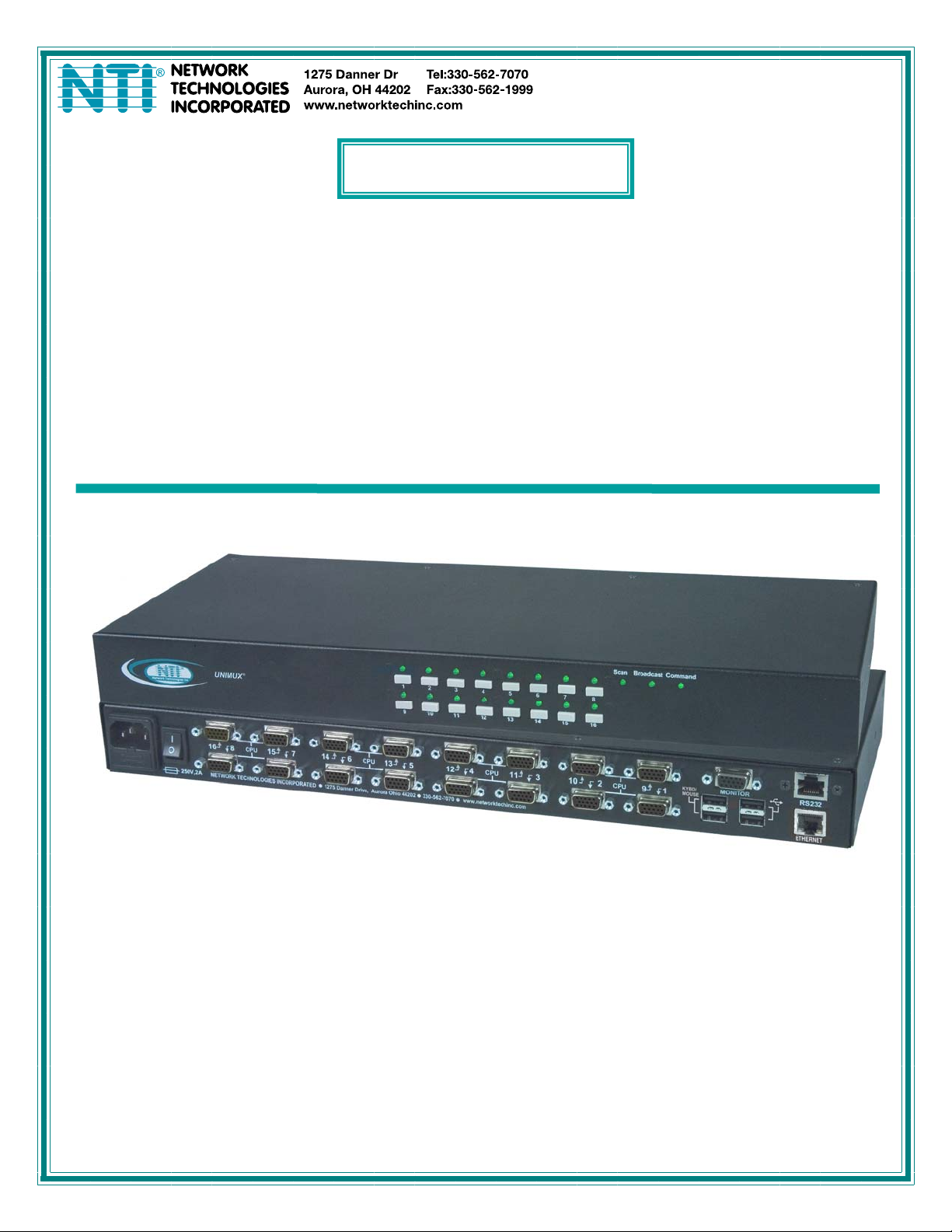
UNIMUX-USBV-xHD(UT)
High Density USB KVM Switch
Installation and Operation Manual
MAN039 Rev 7/23/15

TRADEMARK
UNIMUX is a trademark of Network Technologies Inc in the U.S. and other countries.
COPYRIGHT
Copyright © 2000, 2015 by Network Technologies Inc. All rights reserved. No part of this publication may be reproduced,
stored in a retrieval system, or transmitted, in any form or by any means, electronic, mechanical, photocopying, recording,
or otherwise, without the prior written consent of Network Technologies Inc, 1275 Danner Drive, Aurora, Ohio 44202.
CHANGES
The material in this guide is for information only and is subject to change without notice. Network Technologies Inc
reserves the right to make changes in the product design without reservation and without notification to its users.
FIRMWARE VERSION
Main Controller Firmware Version 1.24
Typographic Conventions
Typeface meaning Font Configuration Example
On-screen computer output Courier New-(not bold)
What you type on the computer Courier New-bold
Keyboard Keys to be pressed as
instructed in the body of a
paragraph
Courier New-bold
Surrounded by < >
General
Character Meaning Example
+
-
When "+" is shown between keystrokes, it indicates a chorded
sequence (press and hold the keys consecutively until all keys
in the sequence are pressed)
When "-" is shown between keystrokes, it indicates to press the
keys consecutively (press and release one at a time)
C:>
C:>edit text.bat
“<L>” means press the “L”
<Ctrl>+<`> (accent/tilde key) is a
chorded sequence to enter Command
Mode.
<A>-<S>-<S>-<E> is a sequence of keys
pressed to enable Security Mode
i

TABLE OF CONTENTS
INTRODUCTION...................................................................................................................................................1
MATERIALS...................................................................................................................... ....................................2
Materials Supplied: .........................................................................................................................................2
Materials Not Supplied, but REQUIRED ....................................................................................................... 2
FEATURES AND FUNCTIONS.............................................................................................................................3
Additional Features............................................................................................................................................4
RACK MOUNTING INSTRUCTIONS....................................................................................................................5
To Mount to a Rack ...........................................................................................................................................5
INSTALLATION.....................................................................................................................................................6
RS232 Connection.............................................................................................................................................9
Ethernet Connection........................................................................................................................................10
Transparent USB Ports....................................................................................................................................10
Limited Extra USB Support.............................................................................................................................. 11
No-Video Models.............................................................................................................................................11
LIMITATIONS......................................................................................................................................................12
USING THE UNIMUX USB KVM SWITCH......................................................................................................... 13
Basic Operation ...............................................................................................................................................13
Front Panel Control..........................................................................................................................................13
Keyboard Control.............................................................................................................................................13
OSD CONTROL..................................................................................................................................................14
Guidelines for Navigating OSD Menus............................................................................................................14
Security Option................................................................................................................................................14
Initial startup .................................................................................................................................................... 15
User Access Functions.................................................................................................................................... 15
Command Mode ...........................................................................................................................................15
Settings.........................................................................................................................................................18
OSD Settings................................................................................................................................................19
Find Mode..................................................................................................................................................... 19
Help Mode.....................................................................................................................................................20
Scan Mode....................................................................................................................................................20
Broadcast Mode............................................................................................................................................ 21
Normal Mode ................................................................................................................................................21
Security............................................................................................................................................................ 22
Enabling Security.......................................................................................................................................... 22
Password and User Name.........................................................................................................................22
User Login.....................................................................................................................................................23
Additional OSD Modes Available With Security Enabled................................................................................ 23
Administration Menu.....................................................................................................................................23
System Configuration ................................................................................................................................... 24
Port Configuration......................................................................................................................................... 24
User Configuration........................................................................................................................................ 25
Edit User Account.........................................................................................................................................25
User Access Control.....................................................................................................................................26
Change Administrator Password..................................................................................................................26
ii

Display Usage...............................................................................................................................................27
Ethernet Configuration..................................................................................................................................27
Idle Timeout.................................................................................................................................................. 28
OSD Blank Timeout......................................................................................................................................28
Alternate Command Hot Key........................................................................................................................28
Reset Port names......................................................................................................................................... 29
Select Keyboard Language .......................................................................................................................... 29
Security Configuration .................................................................................................................................. 30
Serial Baud Rate........................................................................................................................................... 31
Serial Address...............................................................................................................................................31
Keyboard Mapping...........................................................................................................................................32
Key Equivalents...............................................................................................................................................32
Mouse Click Equivalents..................................................................................................................................32
SUN’s 16 Extra Keys ....................................................................................................................................32
SUN RAY SUPPORT.......................................................................................................................................... 34
RS232 CONTROL...............................................................................................................................................34
Remote Connection......................................................................................................................................34
Baud Rate.................................................................................................................................................. 34
Unit Address and Loop Back.....................................................................................................................34
RS232 Command Protocol.............................................................................................................................. 36
RS232 Command Protocol Quick Reference...............................................................................................36
Autostatus..................................................................................................................................................37
NTI Switch Control Program For Windows 9X, NT, 2000, XP, Vista and 7 .................................................... 37
SerTest- RS232 Interface Test Program.........................................................................................................38
Main Options.................................................................................................................................................38
Matrix Operations..........................................................................................................................................38
Setup Options............................................................................................................................................... 38
RMTEST-RS232 Interface Test Program........................................................................................................39
TELNET INTERFACE......................................................................................................................................... 40
Command Summary.....................................................................................................................................40
Command Detail...........................................................................................................................................41
RU-Read Unit Size.................................................................................................................................... 41
RO-Read Connection for Output Port ....................................................................................................... 41
CS- Connect Output Port to Input Port......................................................................................................41
CA- Connect All Output Ports to Input Port............................................................................................... 42
SS_01- Enable Auto Status Mode............................................................................................................. 42
SS_00- Disable Auto Status Mode............................................................................................................42
SX- Examine connections ......................................................................................................................... 43
CC- Save connection configuration into permanent memory at given location ........................................ 43
RC- Read connection configuration from permanent memory at given location.......................................43
RP- Refresh Communication with CPU USB Port.....................................................................................44
Terminate telnet session ...........................................................................................................................44
DEVICE DISCOVERY TOOL.............................................................................................................................. 45
How to Use the Device Discovery Tool........................................................................................................... 45
FIRMWARE UPGRADE PROCEDURE..............................................................................................................46
Requirements .................................................................................................................................................. 46
Preparation For Upgrade................................................................................................................................. 47
Upgrade Procedures........................................................................................................................................48
Start the Bootloader...................................................................................................................................... 48
iii

Update the User Controller Firmware...........................................................................................................49
Update the HID Port Controller Firmware..................................................................................................... 49
Update the Vendor Specific Port Controller Firmware..................................................................................50
Read the Checksum of HID or Vendor Specific Port Controller Firmware................................................... 51
SAFETY STATEMENTS..................................................................................................................................... 52
CABLES ..............................................................................................................................................................52
TROUBLESHOOTING........................................................................................................................................ 53
SPECIFICATIONS .............................................................................................................................................. 53
INDEX..................................................................................................................................................................54
WARRANTY INFORMATION..............................................................................................................................54
TABLE OF FIGURES
Figure 1- Secure rackmount ears to switch.............................................................................................................................5
Figure 2- Secure switch to a rack ...........................................................................................................................................5
Figure 3- Install user monitor.................................................................................................................................................. 6
Figure 4- Install user touch screen monitor.............................................................................................................................6
Figure 5- Install user devices (mouse and keyboard) .............................................................................................................7
Figure 6- Use USB2-AA-5M to extend a device, or a computer.............................................................................................. 7
Figure 7- Connect each CPU using a HDUSBVEXT-xx-MM cable.........................................................................................8
Figure 8- Models without video support, connect using a HDUSB-xx-MM cable.................................................................... 8
Figure 9- Connect cable for RS232 control.............................................................................................................................9
Figure 10- Connect LAN to Ethernet port..............................................................................................................................10
Figure 11- Transparent USB Ports ....................................................................................................................................... 10
Figure 12- Limited Extra USB Support.................................................................................................................................. 11
Figure 13- Cable for USB support only................................................................................................................................. 11
Figure 14- Compatible device combinations......................................................................................................................... 12
Figure 15- Command Mode main menu-User....................................................................................................................... 16
Figure 16- Administrator’s main menu..................................................................................................................................17
Figure 17- Settings menu......................................................................................................................................................18
Figure 18- OSD Settings screen........................................................................................................................................... 19
Figure 19- Find Mode in use................................................................................................................................................. 19
Figure 20- Main Menu help screen....................................................................................................................................... 20
Figure 21- Scan List.............................................................................................................................................................. 20
Figure 22- Broadcast List ...................................................................................................................................................... 21
Figure 23- User login screen.................................................................................................................................................22
Figure 24- Administrator's main menu.................................................................................................................................. 22
Figure 25- User Login screen with........................................................................................................................................23
Figure 26- Administration Mode Menu.................................................................................................................................. 23
Figure 27- System Configuration menu ................................................................................................................................ 24
Figure 28- Port Configuration menu...................................................................................................................................... 24
Figure 29- User Configuration............................................................................................................................................... 25
Figure 30- User Account menu............................................................................................................................................. 25
Figure 31- Access Control list...............................................................................................................................................26
Figure 32- Administrator password menu........................................................................................................................ 26
Figure 33- Usage Statistics Page ......................................................................................................................................... 27
Figure 34- Ethernet Configuration......................................................................................................................................... 27
Figure 35- Change value of Idle Timeout..............................................................................................................................28
Figure 36- Change the value of OSD Blank Timeout............................................................................................................ 28
Figure 37- Alternate Command Hot Key selection window................................................................................................... 29
Figure 38- Press "R" to reset port names .............................................................................................................................29
iv

Figure 39- Select Language menu........................................................................................................................................ 29
Figure 40- Security Configuration ......................................................................................................................................... 30
Figure 41- Login screen with security disabled..................................................................................................................... 30
Figure 42- Adjust Baud Rate.................................................................................................................................................31
Figure 43- Adjust Serial Address.......................................................................................................................................... 31
Figure 44- Keyboard layouts.................................................................................................................................................33
Figure 45- RS232 connection with Matrix-Y-1 cable............................................................................................................. 35
Figure 46- Pinout of Matrix-Y-1 cable ................................................................................................................................... 35
Figure 47- Device Discovery Tool.........................................................................................................................................45
Figure 48- Preparation for firmware upgrade........................................................................................................................ 47
v

NTI UNIMUX SINGLE-USER HIGH DENSITY KVM SWITCH
INTRODUCTION
The UNIMUX-USBV-xHD High Density USB KVM switch (UNIMUX) allows access to any Windows, MAC, or SUN USB CPUs
from one monitor, USB keyboard and USB mouse (up to 32 CPUs). Internal microprocessor circuitry allows all USB CPUs to be
booted simultaneously without keyboard error. Port selection is accomplished by front panel push buttons or comman ds typed o n
the keyboard. Port LEDs and mode status LEDs continuously update on the front panel. Video formats up to 1900X1 200 at
150MHz bandwidth can be displayed from all platforms.
Types of User Input Devices Supported:
• Compatible with most USB keyboards and mice, including Microsoft USB Intellimouse®, Logitech Cordless Elite Du o
keyboard/mouse, Gyration keyboard/mouse, Crystal Vision keyboard with touchpad, and IKEY combo keyboard/touchpad.
Types of CPUs Supported:
Any USB CPU supporting USB version 1.0 or above including:
• USB Windows (all)
• USB MAC
• USB SUN
• Linux
Options:
¾ Two extra USB device ports (total of four) for transparent support of all USB low and full speed accessories- add a “UT” to the
part number (i.e. UNIMUX-USBV-xHDUT)
¾ One extra USB device port (total of three) for limited extra USB support- support for touch screen monitor, interactive
whiteboard, or CAC card reader- add a “U” to the part number (i.e. UNIMUX-USBV-xHDU) LIMITED MODEL
AVAILABILITY
¾ High Density switch with only support for USB keyboard and USB mouse. Remove “V” from the model number.
(i.e. UNIMUX-USB-xHD)
1

NTI UNIMUX SINGLE-USER HIGH DENSITY KVM SWITCH
MATERIALS
Materials Supplied:
• NTI UNIMUX-USBV-xHD(UT) High Density USB KVM Switch
• IEC Power cord- country specific
• Rackmount kit (4, 8, and 16 port models only)
• CD with pdf file of this manual and RS232 control software
• DB9 Female-to-RJ45 Female adapter
• DB25 Female-to-RJ45 Female adapter
• 5 foot RJ45-to-RJ45 CAT5 patch cable
Materials Not Supplied, but REQUIRED
• HDUSBVEXT-xx-MM cable for each CPU being connected to the switch (models with video support)
• HDUSB-3/6-MM -3 or 6 foot cable for each CPU being connected to the switch (models without video support)
Where:
xx is the length of the cable in feet (3,6,10, or 15 feet available)
MM indicates male-to-male connector
Cables can be purchased from Network Technologies Inc by calling 800-RGB-TECH (800-742-8324) or 330-562-7070
or by visiting our website at www.networktechinc.com
See page 52 for some of the available cables.
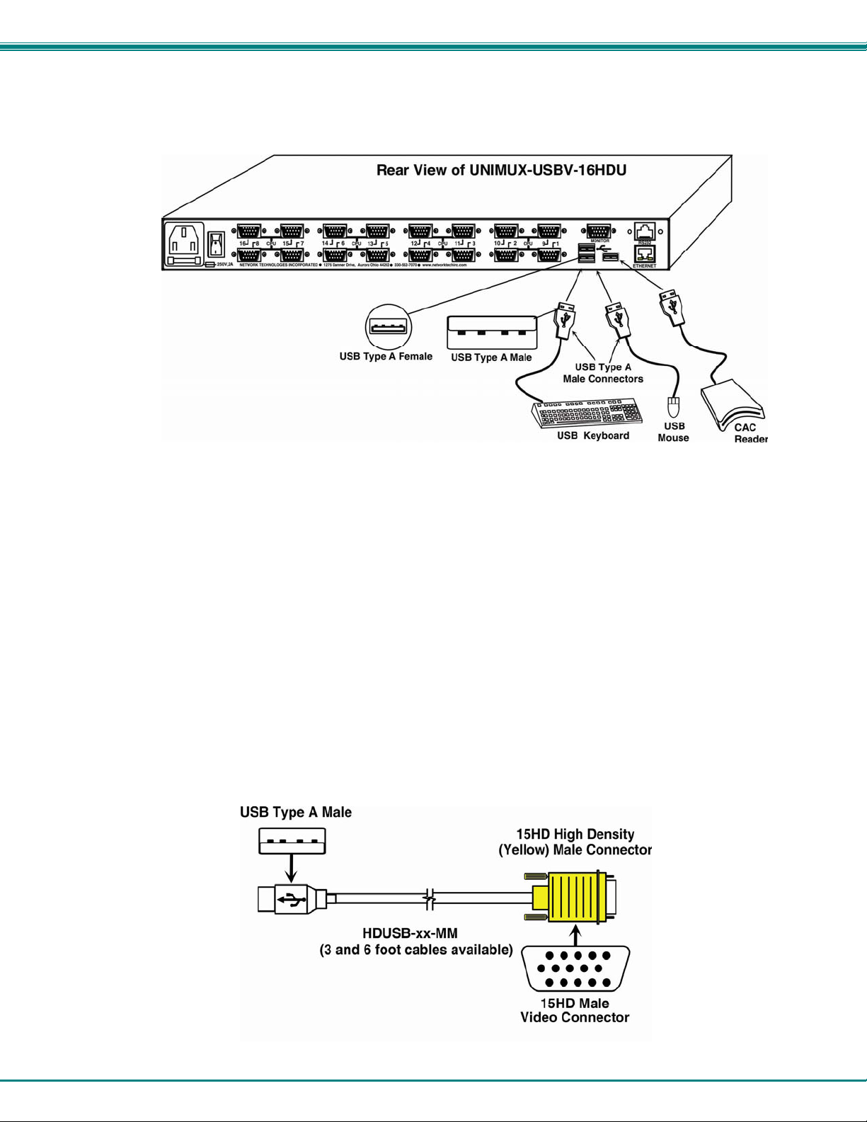
15HD-Male
USB Type A
Male
HD15 Male
Video
USBType A Male
HDUSBVEXT-xx-MM
(3,6,10 and 15 foot cables available)
.
HD15 Male
High Density
15HD-Male
2

NTI UNIMUX SINGLE-USER HIGH DENSITY KVM SWITCH
FEATURES AND FUNCTIONS
#
LABEL CONNECTOR/LED DESCRIPTION
1 CPU Numbers
2 Scan,Broadcast,
Command
---- IEC Connector for attachment of power cord
3
---- Power switch for turning the power to the UNIMUX On/Off
4
5 CPU x
6 KYBD/MOUSE
7 USB Device Symbol
8 MONITOR
9 RS232
13 ETHERNET
Buttons push to manually switch to a specific CPU or change the switch
operating mode
Mode Status LEDs for visual indication of switch operating mode
15HD female
connectors
USB Type A female
connectors
USB Type A female
connector
15HD female
connectors
RJ45 Female
connector
RJ45 female
connector
for connection of CPU cables for video and device support
for connection of user keyboard and mouse
for USB cable from USB (low and full speed) devices (models with
additional transparent USB support only)
for connection of user monitor
for attaching RS232 interface cable from a CPU to control the
functions of one or more switches
for connection to an Ethernet for remote user control via TCP Port
2005 (configurable)
3

NTI UNIMUX SINGLE-USER HIGH DENSITY KVM SWITCH
Additional Features
• Any USB type user device can control any USB CPU (Windows, MAC, and SUN platforms).
• Power cycle circuit control allows the UNIMUX switch to be powered OFF, then ON, at any time without affecting the attached
CPUs. (This assumes that the CPU supports hot plugging.)
• Security features can be enabled.
• A microprocessor is dedicated to each CPU, preventing connected CPUs from locking up.
• Any user device cable can be hot-plugged.
• The front panel LEDs indicate the CPU the user is connected to.
• No dip-switches or jumpers necessary to configure.
• Video formats up to 1920X1200 can be displayed from all platforms.
• Users can control the switch using the On Screen Display (OSD)
• RS232 control allows control of the switch with one CPU serial port. (Windows-based software is provided.)
• NTI Switch Control Program provides easy and powerful graphical control of NTI switches through the RS232 interface.
(Windows only.)
• Optional extra USB ports (2) available for transparent support of USB (low and full speed) devices
4
NTI UNIMUX SINGLE-USER HIGH DENSITY KVM SWITCH
RACK MOUNTING INSTRUCTIONS
This NTI switch was designed to be mounted to a rack or to sit on a desktop. It includes rackmount ears to make attachment to a
rack easy, and rubber feet to be applied to the bottom of the case if it will instead sit on a flat surface. If this will sit on a flat
surface, simply apply the rubber feet to the bottom of the case in each of the 4 corners.
To Mount to a Rack
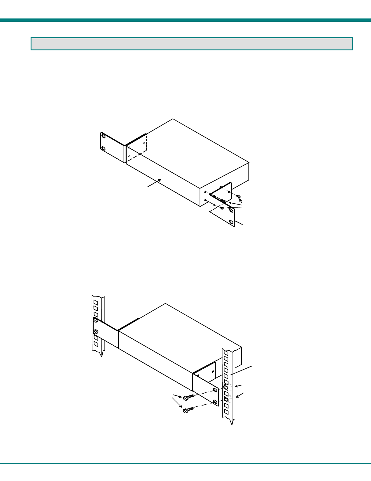
1. Attach the ears to the switch using the 6-32x3/16" flat Phillips-head screws (6) provided as shown in the illustration below.
The holes in the ears should line up with pre-threaded holes in the sides of the NTI switch. Tighten the screws securely.
Front of Switch
NTI Switch
6-32x3/16"
Flat Head
Screws
(Provided)
Rackmount Ear
Figure 1- Secure rackmount ears to switch
2. Install 4 captive nuts (not provided) to the rack in locations that line up with the holes in the mounting ear on the NTI switch.
3. Secure the NTI switch to the rack using four 3/16" diameter screws (not provided). Each screw should be of sufficient length
to go completely through the NTI mounting ear, rack frame and fully engage all threads in the captive nut. Be sure to
tighten all mounting screws securely.
4. Attach all cables securely to the switch and where necessary supply adequate means of strain relief for cables.
3/16" Diam eter Screw s
(not provided)
NTI Switch
Rack
Captive Nuts
(not provided)
Figure 2- Secure switch to a rack
5

NTI UNIMUX SINGLE-USER HIGH DENSITY KVM SWITCH
INSTALLATION
It is not necessary to turn OFF power to CPUs or monitors during this installation unless RS232 is going to be connected. All
cables, except for the RS232 cables, may be hot plugged.
If using RS232 Control see RS232 section on page 34 for more information. Observe normal precautions when connecting the
RS232 cables to the CPU. Refer to the owner’s manual for the CPU being connected for precautions, if any.
1. Connect the 15HD male cable end from the user monitor to the female black 15HD port marked “MONITOR x” on the rear of
the UNIMUX switch (see Figure 3 ). If a touch screen monitor is being connected (models with touch screen support only),
connect the USB cable from the monitor to any one of the USB type A connectors in the same user device port group
(see Figure 4 ).
Figure 3- In stall user monitor
Figure 4- Install user touch screen monitor
6

NTI UNIMUX SINGLE-USER HIGH DENSITY KVM SWITCH
2. Connect the user devices to the USB type A female ports labeled “KYBD/MOUSE” on the rear of the UNIMUX switch (see
Figure 5 ). Connection to these ports will provide user control of the UNIMUX switch.
Note: If there are four (4) USB type A female ports present (models with transparent USB support only), then the two
additional USB ports labeled with the USB symbol ( ) are available for connection of any USB device. However,
the keyboard and mouse intended to control the UNIMUX switch must be connected at the USB ports labeled
“KYBD/MOUSE”.
Note: If device cables are not long enough to reach the UNIMUX switch, they can be extended up to 20 meters using up
to 4 NTI USB2-AA-5M USB 2.0 Active Extensions (see Figure 6)- purchased separately. Contact yo ur NTI salesperson for
more details by calling (800) 742-8324 (800-RGB-TECH) or (330) 562-7070 or visit our website at
http://www.networktechinc.com
.
Figure 5- Install user devices (mouse and keyboard)
TO UNIMUX
SWITCH
USB TYPE A
MALE CONNECTO R
USB2-AA-5M
USB TYPE A
FEMALE CONNECTOR
Figure 6- Use USB2-AA-5M to extend a device, or a computer
7
USB KEYBOARD

NTI UNIMUX SINGLE-USER HIGH DENSITY KVM SWITCH
3. For each CPU:
• Connect a USB type A cable end of a HDUSBVEXT-xx-MM cable to a USB type A female user device port on a CPU.
• Connect the 15HD blue male cable end of a HDUSBVEXT-xx-MM cable to the video port of the same CPU.
• Connect the 15HD yellow male cable end of the HDUSBVEXT-xx-MM cable to a “CPU x” port on the UNIMUX
switch. (See Figure 7)
Figure 7- Connect each CPU using a HDUSBVEXT-xx-MM cable
Figure 8- Models without video support, connect using a HDUSB-xx-MM cable
8
NTI UNIMUX SINGLE-USER HIGH DENSITY KVM SWITCH
4. Power-up
• The UNIMUX can be powered at any time.
• The CPUs can be powered at any time although if a CPU needs a keyboard and/or mouse at power-ON it should be po wered
after connecting to and powering-ON the UNIMUX.
• The keyboard and mouse (only) can be hot plugged to and from the UNIMUX at any time.
Note: The order in which the CPUs and switch are powered up does not matter. A power strip can be used.
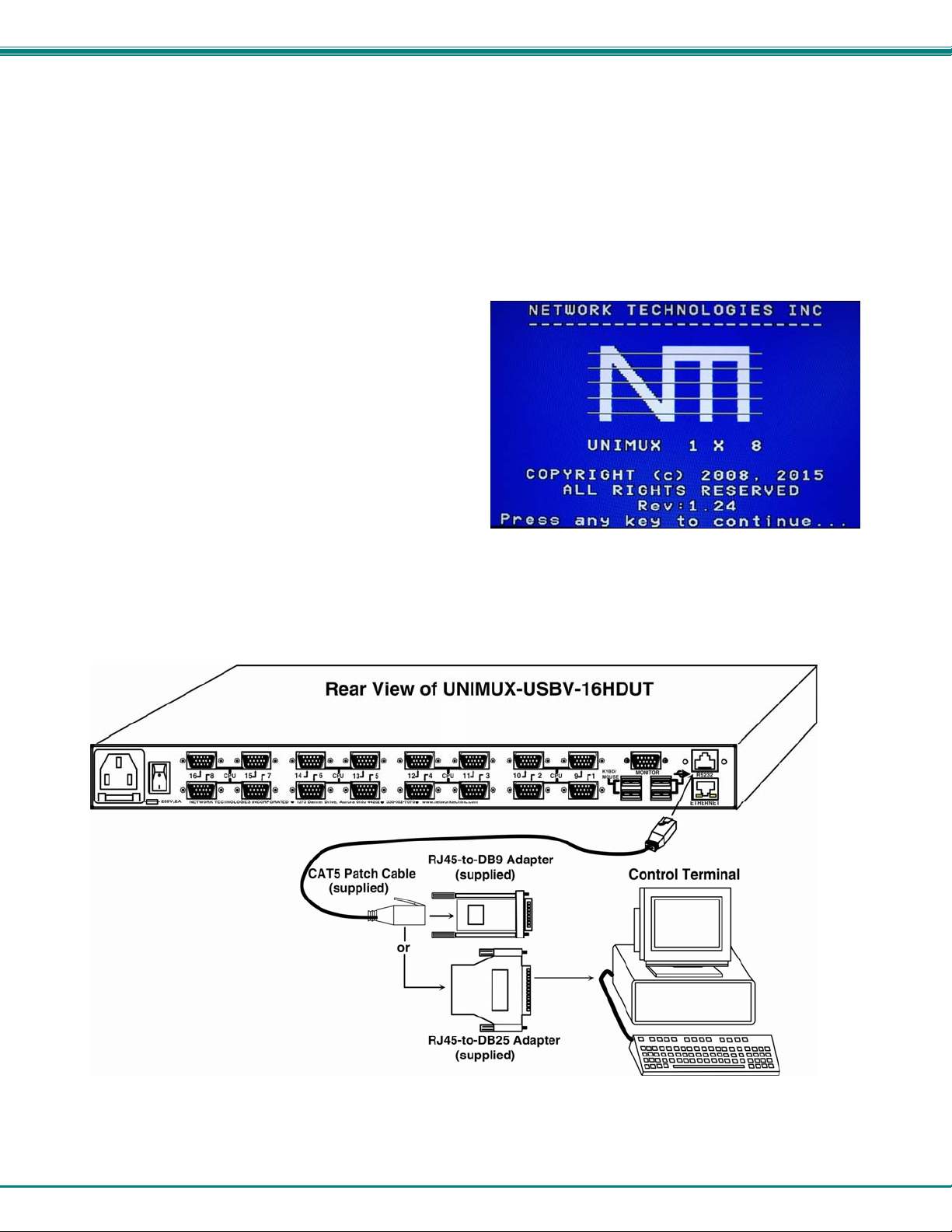
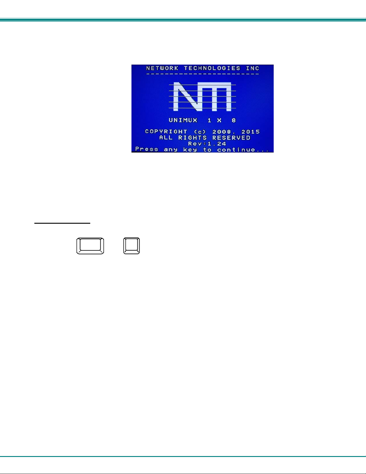
Immediately after powering ON the UNIMUX, the following splash screen will appear on the monitor if the OSD option is built into
the switch:
If the security option is enabled (see page 14 for details on the
"Security Option"), when the UNIMUX is powered up the user
will be prompted for a username and password to continue.
If the security option is not enabled the monitor will display the
desktop image for the connected CPU and the user can
continue with normal operation of the connected CPU.
RS232 Connection
If RS232 control will be used, connect one end of the CAT5 patch cable (supplied) to the port labeled “RS232” o n the rear of the
UNIMUX. Plug the other end of the CAT5 cable into either the RJ45-to-DB9 or RJ45-to-DB25 adapter supplied, and connect the
adapter to the RS232 port on the control terminal. Follow the instruction under “RS232 Control” on page 34 for config uration and
use of the RS232 control feature.
Figure 9- Connect cable for RS232 control
9
NTI UNIMUX SINGLE-USER HIGH DENSITY KVM SWITCH
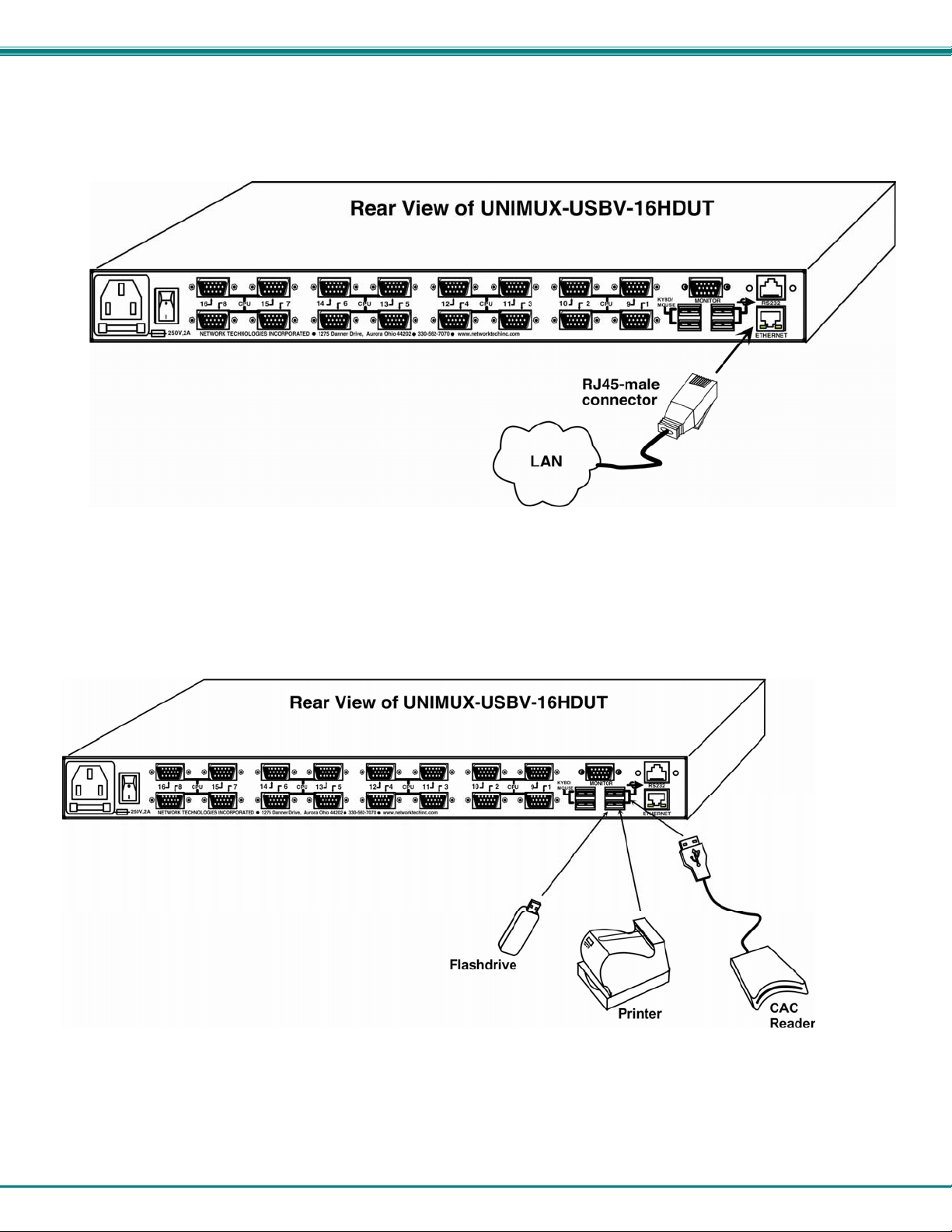
Ethernet Connection
If the Telnet Interface will be used (page 40), and Ethernet connection to the Local Area Network (LAN) must be made using
CAT5 cable with RJ45 connectors attached. Wiring between the connectors should be straight thru (pin 1 to pin 1, pin 2 to pin 2,
etc.). Connect a CAT5 cable between the port labeled “ETHERNET” on the rear of the UNIMUX and the LAN.
Figure 10- Connect LAN to Ethernet port
Transparent USB Ports
If the UNIMUX you have purchased includes the transparent USB ports option (UNIMUX-USBV-xHDUT), then it supports the
connection of any USB (low- and full-speed) device. Devices such as CAC card reader, flash drives, whiteboards, printers, etc
will connect to the PC attached to the selected “CPUx” port.
Figure 11- Transparent USB Ports
10
NTI UNIMUX SINGLE-USER HIGH DENSITY KVM SWITCH
Limited Extra USB Support
If the UNIMUX you have purchased includes only one extra USB port for a total of three (UNIMUX-USBV-xHDU), then extra
support is limited to the connection of a touch screen monitor, interactive whiteboard, or CAC card reader. When used, the
additional USB device will connect to the PC attached to the selected “CPUx” port.
Figure 12- Limited Extra USB Support
No-Video Models
Some models of UNIMUX Hi Density USB KVM Switch have been specially designed without support for video. As
such, the OSD menu control described in this manual cannot be used. To control the No-Video version of this
product, use the following control methods described in the manual:
• front panel control using touch-switches and LEDs (see page 13)
• RS232 control (see page 34)
• Telnet Interface- via command line interface (see page 40)
Note: Ethernet configuration cannot be changed using the OSD menu in the absence of video support.
Instead, to change network settings, use the NTI Discovery Tool provided on the CD (page 45). (Default
configuration settings can be found on page 27.)
Cables are available from NTI having only the 15HD high density connector at one end and USB Type A male
connector at the other end (HDUSB-x-MM where x = 3 or 6 feet).
Figure 13- Cable for USB support only
11
NTI UNIMUX SINGLE-USER HIGH DENSITY KVM SWITCH
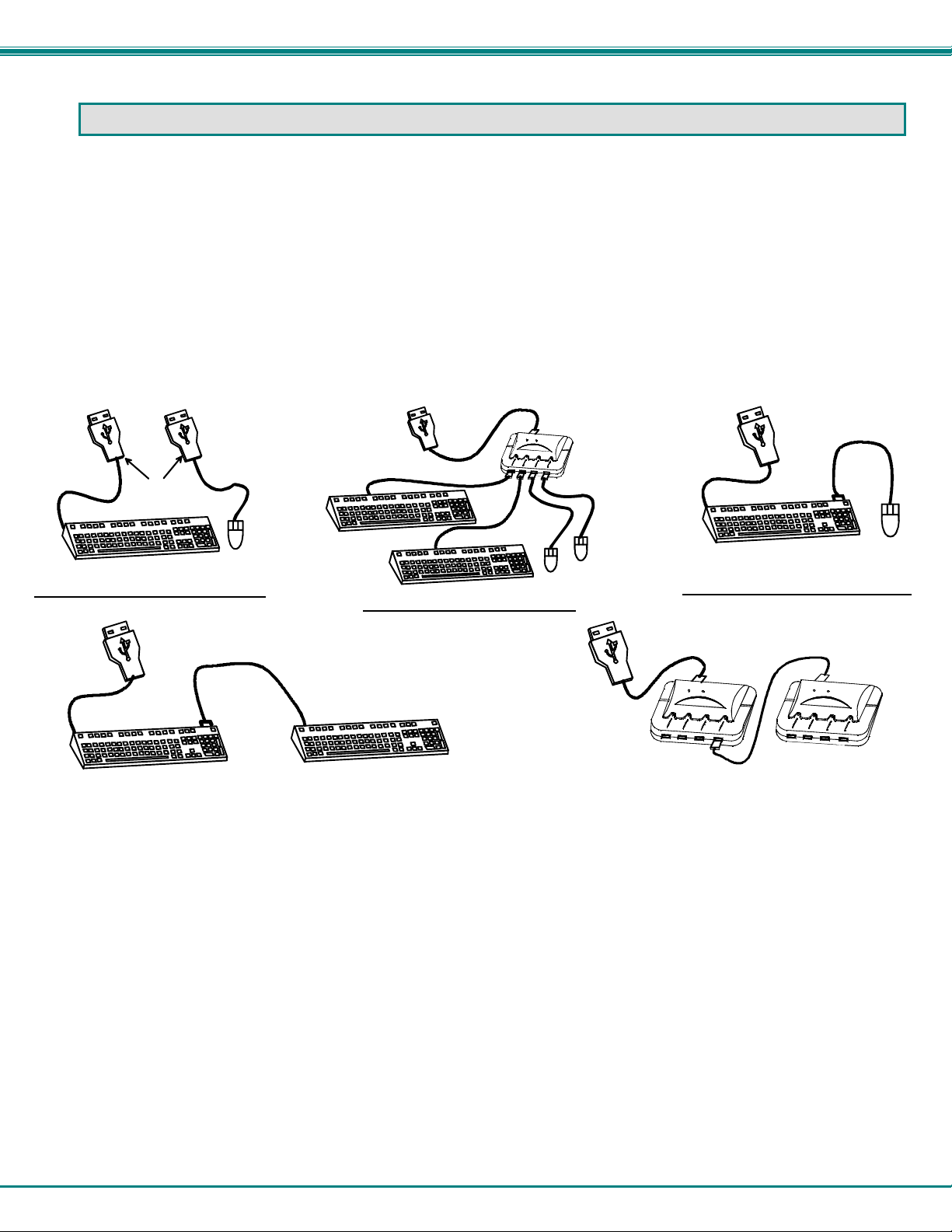
LIMITATIONS
• Only two non-HID (Human Interface Device) can be connected at a time (device other than keyboard or mouse)
• A USB hub (single or multi-port) can be used.
• Only a USB Windows or SUN keyboard or USB mouse may be connected to the USB port on a USB MAC keyboard
• A maximum of 5 input devices may be connected to the UNIMUX at the “KYBD/MOUSE” ports either directly or through hubs.
See Figure 14 for some examples of input device combinations that can be used with the UNIMUX.
Typical Installation- 1 Keyboard, 1 Mouse
USB Type A
Male Connectors
USB Windows Keyboard
USB MAC Keyboard
USB
Mouse
USB Windows Keyboard
USB Windows Keyboard
Optional- Multiple keyboards and mice
USB MAC Keyboard
USB
Mouse
USB
Hub
USB
Mouse
USB MAC Keyboard
Optional- MAC USB keyboard and mouse
2 USB hubs in series (Daisy-Cha ined)
USB
Mouse
Figure 14- Compatible device combinations
12

NTI UNIMUX SINGLE-USER HIGH DENSITY KVM SWITCH
USING THE UNIMUX USB KVM SWITCH
Basic Operation
Once the UNIMUX is properly connected, the UNIMUX will enable a connection to be made between the CPUs attached to its
VIDEO and CPU ports and the monitor and input devices attached to the MONITOR and DEVICES ports. The LEDs on the
control panel of the UNIMUX will illuminate depending on w hich port (and corresponding CPU) is being connected to the monitor
and input devices.
The UNIMUX can be controlled by four methods:
• front panel control using touch-switches and LEDs
• OSD control via the user devices (models with video support only)
• RS232 control (see page 34)
• Telnet Interface- via command line interface (page 40)
Front Panel Control
There is a touch-switch and LED on the front panel of the UNIMUX for each CPU the switch will connect the monitor and
input devices to. Pressing any touch-switch on the front panel of the UNIMUX will connect the corresponding CPU to the monitor
and input devices.
Holding down any front panel touch-switch for more than 2 seconds will cause the UNIMUX to cycle through all modes of
operation including COMMAND, BROADCAST, SCAN, and NORMAL (described starting on page 20). The three MODE LEDs on
the front panel indicate which mode is selected. Release the touch-switch when the LEDs indicate the de sired mode. When no
mode LEDs are illuminated the user is in Normal Mode controlling directly the CPU to which the user is connected through the
UNIMUX.
If the UNIMUX includes the Transparent USB option (UNIMUX-USBV-xHDUT), and if the USB Device Warning is enabled
(Setting, page 18), then pressing any touch-switch on the front panel will not immediately connect the corresponding CPU to the
monitor and input devices. With the first press of any touch-switch (momentary or extended), a device warning (below) will popup on the user’s monitor.
To use COMMAND, BROADCAST,
or SCAN mode, we recommend
that you disable the device warning
first. See page 18.
Select “N” to properly eject your devices through the CPU operating system before switching ports, and then return to the OSD
menu to switch ports or press the touch-switch twice more to make the change in port connection.
Select “Y” to proceed with a port change to another CPU. Any devices connected to the transparent USB ports will automatically
connect to the newly selected CPU.
If a touch-switch is pressed a second time instead of just once, this device warning will be bypassed and the port change will
proceed immediately.
Device warning
Keyboard Control
Keyboard control of the UNIMUX can be achieved using OSD Command Mode. Command Mode is operated using the keyboard
and mouse in conjunction with OSD menus superimposed onto the monitor. For all models use the menus as instructed on page
12.
By pressing <Ctrl> + < ` > (accent key), the user can enter Command Mode. Once in Command Mode, typing a series of
commands will cause the UNIMUX to connect the user to any one CPU connected to the switch. Pressing the <Esc> key will exit
Command Mode.
13

NTI UNIMUX SINGLE-USER HIGH DENSITY KVM SWITCH
OSD CONTROL
(OSD Control applies only to UNIMUX models with video support)
OSD superimposes a menu system on the user’s video screen with a list of all connected CPUs. OSD allows CPUs to be named
(with up to 12 character names). OSD then allows selection of CPUs by that name. Connected CPUs can be listed by name or
by port number. OSD Search Mode enables the user to type in the first few characters of the CPU's name and the OSD will
locate it. HELP screens assist with all OSD functions.
Guidelines for Navigating OSD Menus
Throughout this manual, various rules apply to navigating the menus used to control and operate the UNIMUX.
• OSD menus can be navigated using the mouse, the arrows on the keyboard, hot keys (highlighted in red) and the
<Page Up>, <Page Down>, <Home>,<Tab> and <End> keys.
- The <up arrow> and <down arrow> moves the cursor up or down one line item at a time in a scrollable
window, or between menu items in a menu item list
- The <left arrow> and <right arrow> will move the cursor left or right through menu items or while in
editable fields (such as when editing port names)
- <Page Up> and <Page Down> increase/decrease the listed ports by one page at a time
- <Home> will jump to the beginning of the list
- <Tab> will jump between selectable fields, left to right
to move between menu items
- <Shift>+<Tab> will jump between selectable fields, right to left
- <End> will jump to the end of the list.
• Only alphabetic and numeric characters can be typed in the OSD menu fields
• Positioning the mouse cursor over a menu function or CPU name will highlight the background (green highlight for
menu functions, cyan or light blue for CPUs)
• The scroll bar can be used by clicking on the corresponding up and down arrow above and below the scroll bar.
• The mouse wheel may b e used to move the selection bar
• The <Shift> key must be used to enter an uppercase letter within all OSD menus.
• Clicking on a listed CPU while in Command Mode will connect the user to that CPU.
• Available functions will have white characters with one red character. The red character corresponds to a keyboard
“hot key”. Hot keys are not case sensitive. Functions that are not available will be transparent.
• When changing characters for names, passwords, or values within an edit field, click on the field or select an d press
<Enter> to enter the field for editing, and press <Enter> again to exit th e edit field.
• To exit (and step back 1 menu) from any menu, press <Esc> on
• All screens that include “F1:Help” for context-sensitive help will also respond to pressing the <F2> key to provide
“Global Help” screens with basic menu navigation help.
the keyboard .
Security Option
The security option in the OSD Control of the UNIMUX USB KVM switch enables an administrator to control access to CPU ports
for each user. Up to 63 users can be created. These users have controlled access to any CPU. Only the administrator can
activate or deactivate the security features on the user port. Finally, the administrator can set a maximum idle time value after
which the current user will be logged out and the login screen displayed again if the user has no activity. The current security
status, idle time out, and scan dwell time are all saved and will be restored whenever power to the switch is cycled OFF, then ON.
To reset the administrator's password call NTI and have the device serial number of the UNIMUX available. For more on
security, see page 22.
14
NTI UNIMUX SINGLE-USER HIGH DENSITY KVM SWITCH
Initial startup
When the UNIMUX is first powered ON, a splash screen similar to the following will appear:
Press any key and the UNIMUX will connect you to the first CPU port with a connect ed CPU that is powered ON.
To access Command Mode and connect to a different port or perform other user access functions (see below), press <Ctrl> +
<`> (accent/tilde key).
User Access Functions
Command Mode
In order to control the switch with the keyboard, Command Mode must be enabled. To enable Command Mode from the
keyboard:
(ACCENT/TILDE
Press
All the status lights on the keyboard will illuminate to indicate that Command Mode is enabled. At this point, the Command Mode
menu will be displayed.
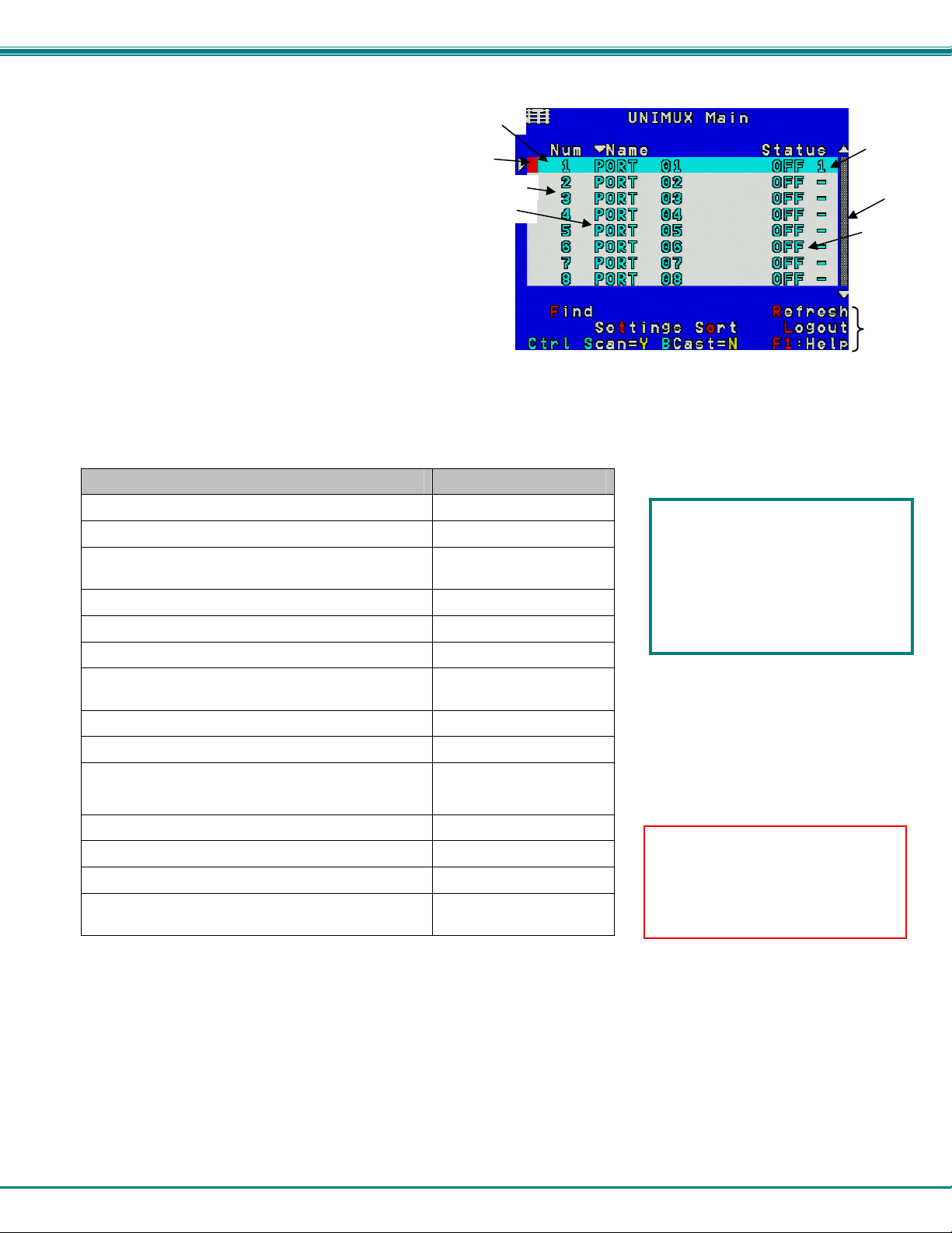
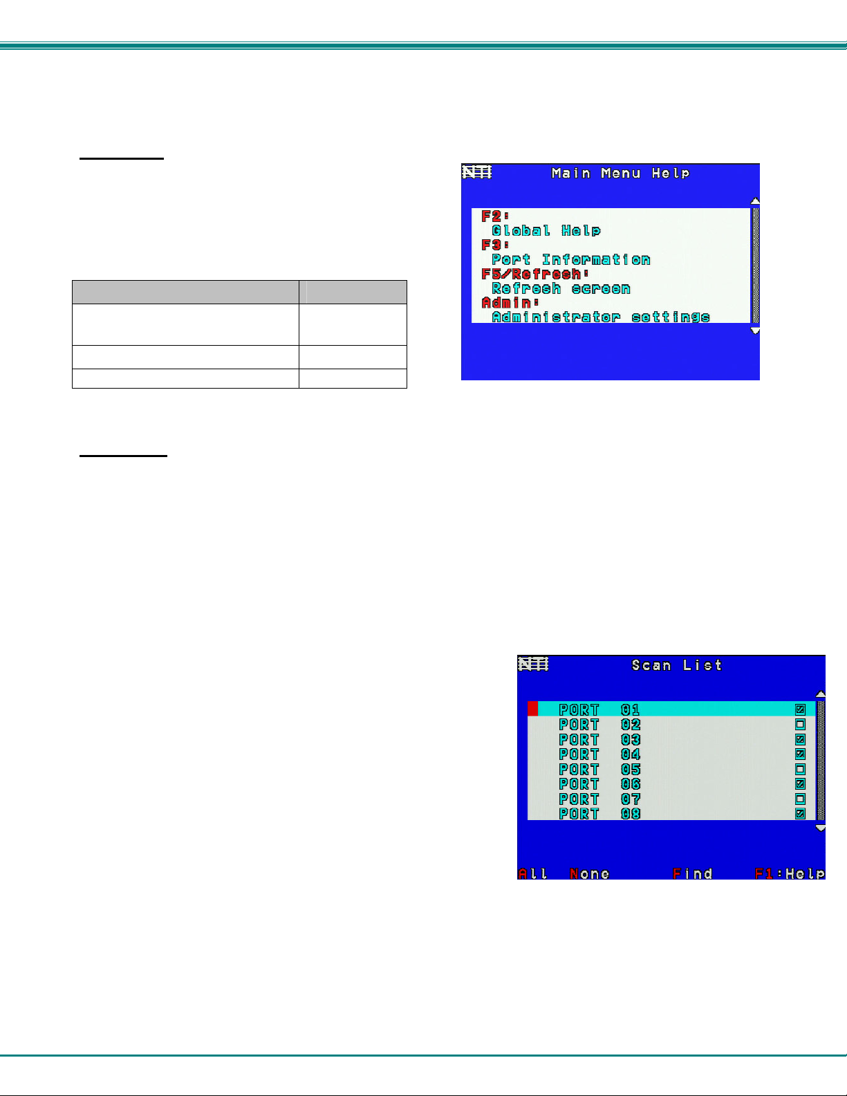
The Command Mode menu (see Figure 15) lists all CPUs by name and port number. Only 8 ports are listed on the screen at a
time. To view the other portions of the list, scroll using the arrow keys on the keyboard or use the mouse to click on the arrows on
the scroll bar in the OSD menu. When the Command Mode main menu is displayed, the first displayed port in the list will be the
port the current user is connected to, followed by the next seven consecutively numbered ports. (Alternatively the list may be
sorted alphabetically- press the letter <O> to toggle sort method.) The names of accessible ports are displayed with blue
characters. If Security is activated, the access rights for the user logged-in may not include all ports. Names of restricted access
ports are displayed in black.
Ctrl
+
~
`
`
KEY)
15
NTI UNIMUX SINGLE-USER HIGH DENSITY KVM SWITCH
U
I
An arrow to the left of a port number in the list indicates
the port the user is currently connected to. From
left to right, the columns display the following:
• Port Number
• Port Name
• Power Status of the CPU (ON/OFF)
Note: “NAC” indicates a non-accessible
computer for that user
• The actual user number (1-8) connected to the CPU.
• If no user is connected to a CPU, the user number is
replaced by a "–" (dash).
Selection
Bar
Cursor
Port Number
Port Name
Figure 15- Command Mode main menu-User
Note: While in Command Mode, the numbers on the NUM PAD on the keyboard are not active. If numbers are required
while in Command Mode, use the numbers on the main key bank.
The list below describes the command functions available from the keyboard within the OSD mode of control after entering into
Command Mode:
Function Keystroke
Select the previous port
Select the next port
Go to specific port- Press any valid number from 1-
1024 to connect to a desired port.
Increases the ports listed by 1 page
Decreases the ports listed by 1 page
Enter “Settings” menu
Toggle ports listed to view by port number or
alphabetically by port name
Enable/disable Scan Mode
Enable/disable Broadcast Mode
Enter Administrator menu
(only available if the Administrator is logged in)
Select the first port on the switch
Select the last port on the switch
Display Help menu
Global Help- display window navigation tips used
throughout all menus
up arrow
down arrow
port # - Enter
Page Down
Page Up
T
O (letter, not
number)
Ctrl + S
Ctrl + B
A
Home
End
F1
F2
If the USB Device Warning is
enabled (page 18), changing ports
using the Up Arrow, Down Arrow,
or typing the port number and
pressing <Enter> will prompt the
warning message to pop up (page
17), requiring a response from you
before proceeding.
Note: The user must exit
Command Mode to type to a CPU.
To exit Command Mode press
<Esc> on the keyboard.
ser
Scroll Bar
Power
Menu
tems
16

NTI UNIMUX SINGLE-USER HIGH DENSITY KVM SWITCH
Function Keystroke
Enter Find Mode, add a character to search string
and select the CPU’s name that matches best.
Type any alphabetical or numeric character (A-Z, 0-9)
Note: use is not case sensitive
Switch to selected port
Logout (you will be prompted for confirmation)
Exit Command Mode
F
Enter
L
Esc
Figure 16- Administrator’s main menu
USB Device Warning
(Applies to models with Transparent USB option only (UNIMUX-USBV-xHDUT)
When you choose to switch ports, if the USB Device Warning is enabled (see Settings on page 18), you will be prompt ed for a
confirmation “Y” or “N” to proceed. This provides the user with a reminder and opportunity to close the OSD menu and properly
use the operating system to eject any USB device connected to the transparent USB ports (labeled with USB symbol- )
on the UNIMUX. Otherwise, if a flash drive or external hard drive is connected to a USB port, data on it may be corrupted if the
device is not safely stopped/ejected before switching ports.
Select “N” to properly eject your devices through the CPU operating system before switching ports, and then return to the OSD
menu.
Select “Y” to proceed with a port change to another CPU. Any devices connected to the transparent USB ports will automatically
connect to the newly selected CPU.
17

NTI UNIMUX SINGLE-USER HIGH DENSITY KVM SWITCH
Settings
To enter the Settings menu (see Figure 17) press <T> from the Command Mo de menu. The list below describes the Settings
menu functions available from the keyboard:
Function Keystroke
Open OSD Settings screen
Go to Broadcast list
Go to Scan list
Change the scan dwell time period
Enter any value from 002-255
(for more on this-see “Scan Mode”
page 20)
Enable/Disable right mouse button
click emulation with Apple 1-button
mouse (see “Mouse Click
Equivalents” on page 32 for more)
Enable/Disable reminder warning for
ejecting USB device on connected
CPU before proceeding to switch to a
new CPU (on models with
transparent USB port option only)
See page 17 for more.
Exit from Settings menu
Return to Main menu
O
B
S
T
R
U
Esc
Figure 17- Settings menu
When the <T> is pressed, the current value of the scan dwell time is selected with an edit field (see Figure 17) . The user can
introduce a new value for scan dwell time and press <Enter> to save it or <Esc> to exit. Any value between 002 and 255
(seconds) is acceptable.
Note: When using Scan Mode, we recommend that the USB Device Warning be disabled. Otherwise, when the UNIMUX
tries to switch from one port to another, the operation will pause waiting for a “Y” response to proceed to the next port.
18
NTI UNIMUX SINGLE-USER HIGH DENSITY KVM SWITCH
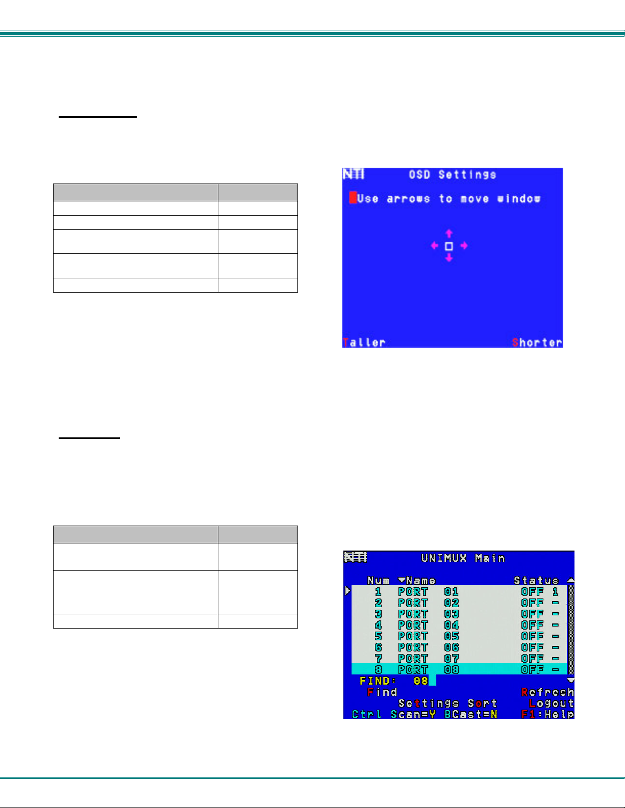
OSD Settings
The OSD Settings screen enables the user to adjust the height of the OSD screen on the monitor and the position of it. The
position can be adjusted both horizontally, as well as vertically. Press <O> from the Settings menu (page 18) to open the OSD
Settings screen.
Function Keystroke
Make OSD window taller
Make OSD window shorter
Move OSD window vertically
Move OSD window horizontally
Exit and save OSD Settings
T
S
up or down
arrow
left or
right arrow
Esc
Figure 18- OSD Settings screen
Find Mode
Find Mode is enabled by typing any alphabetical or numeric characters while in the Command Mode mai n menu, or by pressing
<F> while in supporting menus.
Find Mode allows the user to enter and maneuver through a list of CPU names. The CPU name best matching the characters
typed is selected. The list of CPUs may also be searched for a specific (or similar) name. The Find Mode function is not case
sensitive. The following commands are valid when the search option has been invoked from Command Mode.
Function Keystroke
Erase previous character in search
name
Add a character to the search
string and select the best
matching CPU name
Exit Find Mode
Backspace
A-Z, 0-9
(upper or
lower case)
Esc or Enter
Figure 19- Find Mode in use
19
NTI UNIMUX SINGLE-USER HIGH DENSITY KVM SWITCH
Help Mode
To enter Help Mode press the <F1> key from the Command Mode
menu (see page 13).
Help Mode displays a list of commands with a short explanation of
their function. The following options allow the user to quickly
obtain information on any command
Function Keystroke
View the previous page of help
if available
View the next page of help if available
Exit Help Mode
Figure 20- Main Menu help screen
.
Page Up
Page Down
Esc
Scan Mode
Using Scan Mode, the user can automatically switch from one CPU to another in predetermined config urable time intervals. The
CPU ports to be scanned are easily selected provided the user has access to them. At initial startup, the user as access to all
CPU ports by default.
To activate or deactivate Scan Mode press <Ctrl> + <S> from the Command Mode menu. The text shown in the menu (see
Figure 16) will toggle between “Scan=N” and “Scan=Y”, each time the <Ctrl> + <S> keys are pressed. When “Scan=Y” is
shown, Scan Mode is active. When “Scan=N” is shown, Scan Mode is OFF.
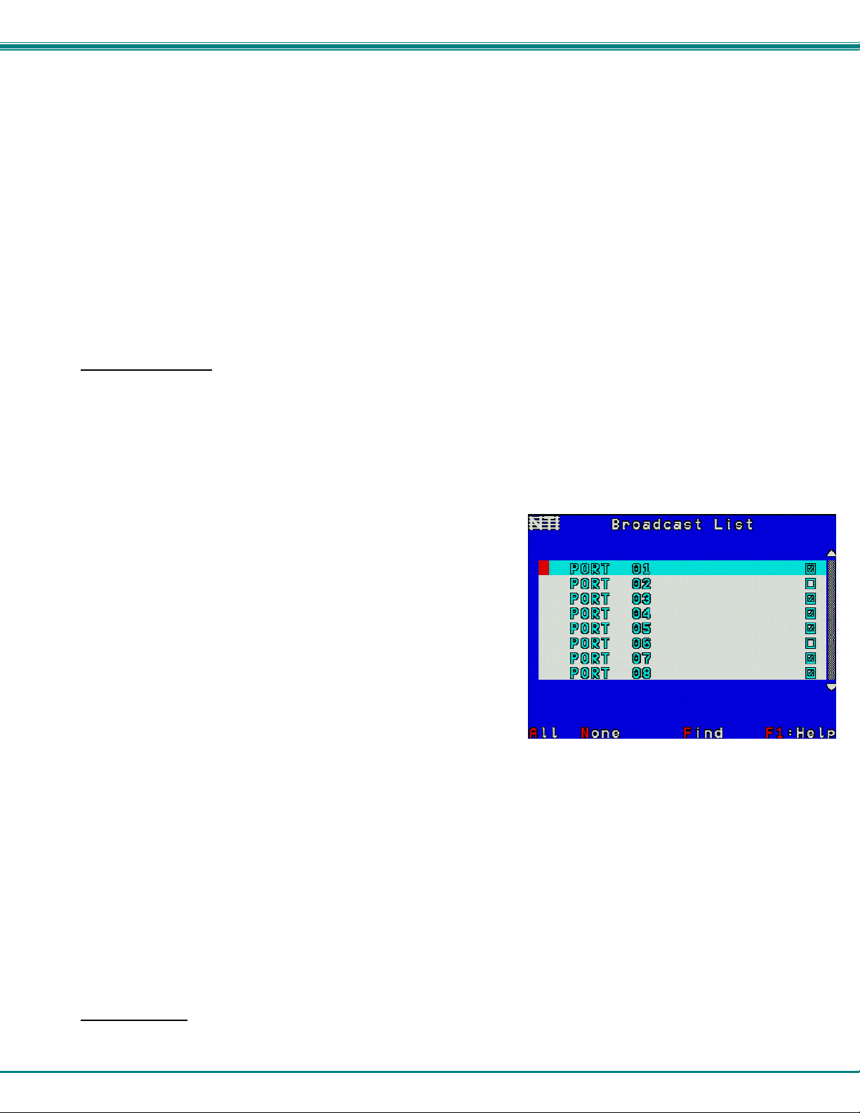
From the Settings menu (see page 18) press <S> to access the “Scan List”. The Scan Li st enables the user to select specific
ports to be active in Scan Mode. While active, the user will have full device control of the con nected port. Only the selected
ports will be scanned in Scan Mode.
The “Scan List” is a check list with all the port numbers displayed
• unchecked box = the corresponding port is not in the scan list
• checked box = the corresponding port is in the scan list
From the “Scan List” the user can:
• toggle the state of the selected port (press <Spacebar>)
• select all ports to be scanned (press <A>)
• deselect all ports so that none are scanned (press <N>)
• find a specific port to either select or deselect (press <F> ,
then any alphabetical or numeric character to locate the desired port).
Figure 21- Scan List
A port is skipped from the scan cycle if one of the following conditions is true:
- the port is not in the Scan List
- Security Mode is enabled and the user does not have access rights to the port
- the CPU connected to the port is OFF
20
NTI UNIMUX SINGLE-USER HIGH DENSITY KVM SWITCH
When switching to a new port the port name is displayed by OSD in the left upper corner of the monitor for 5 seconds or until a
key is pressed or the mouse is moved, whichever comes first. The scan dwell time is programmable from 2 to 255 seconds
(default time-out period is 5 seconds). While using the mouse, keyboard or touchscreen the scanned port becomes active and
scanning is stopped. The switch will resume scanning after a period of user inactivity determined by the scan dwell time. See
Settings Menu on page 18 for configuring the scan dwell time.
To return to the Settings menu, press <Esc>. The scan selection list is automatically saved.
Note: The scan dwell time set by the user affects all users.
Note: The keyboard, mouse and touchscreen must remain idle for the full scan dwell time before the switch selects the
next active port.
Broadcast Mode
To activate or deactivate Broadcast Mode press <Ctrl> + <B> from the Command Mode menu. The text shown in the menu
(Figure 16) will toggle between “BCast=N” and “BCast=Y”, each time the <Ctrl> + <B> keys are pressed. When “BCast=Y” is
shown, Broadcast Mode is active. When “BCast=N” is shown, Broadcast Mode is OFF.
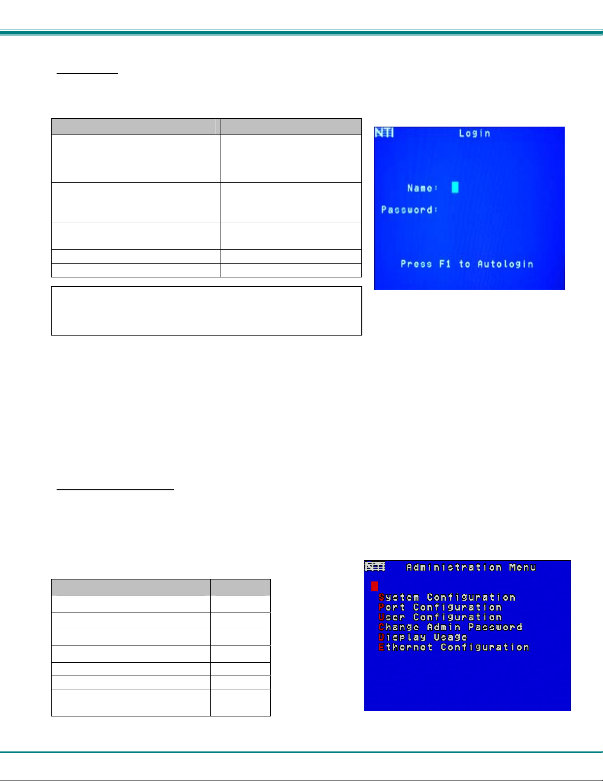
Broadcast Mode enables the user to type characters to more computers simultaneously. From the Settings menu (see page 18)
press <B> to access the “Broadcast List” where the user can edit the list of ports that receive data in Broadcast Mode.
The “Broadcast List” is a check list with all the port numbers displayed
• unchecked box = the corresponding port is not in the broadcast list
• checked box = the corresponding port is in the broadcast list
From the “Broadcast List” the user can:
• select all ports to be broadcasted to (press <A>)
• deselect all ports so that none are broadcasted to (press <N>)
• select only a limited number of ports to be broadcasted to
• find a specific port to either select or deselect (press <F> ,
then any alphabetical or numeric character to locate the desired port).
Figure 22- Broadcast List
A port doesn’t receive broadcast data if one of the following conditions is true:
- the port is not in the Broadcast List
- Security Mode is enabled and the user does not have access rights to the port
Note: The user must type somewhat slowly when in Broadcast Mode (less than 20 wpm) and cannot use the
<Backspace> key.
Note: The mouse and touchscreen will be disabled while in Broadcast Mode.
To return to the Settings menu, press <Esc>. The broadcast selection list is automatically saved.
Normal Mode
When the UNIMUX switch is not in Command, Scan, or Broadcast mode and the OSD control is not active on the monitor, the
user is in Normal Mode, controlling the CPU to which the user is connected through the UNIMUX switch.
21

NTI UNIMUX SINGLE-USER HIGH DENSITY KVM SWITCH
Security
Enabling Security
To enable the security feature the administrator must first enter Command Mode. If the Command Mode menu is not already
displayed, press <Ctrl> + <`> (accent/tilde key). The OSD menu will automatically appear on the monitor.
To login as the administrator, the user must first logout by pressing <O>, and then <Y> to confirm. A login prompt will appear.
Password and User Name
The factory settings are:
• default user name = <root>
• default password = <nti>
Note: The username for the administrator cannot be changed
from "root”.
Figure 23- User login screen
Note: The <F1> Autologin key (see Figure 25) is only for use by users other than the administrato r, an d is only displayed
and available for use if security is not enabled.
With a valid login, the user will be connected to the first CPU that is powered-ON. To enter Command Mode, press <Ctrl> +
<`> (accent/tilde key). The OSD menu will automatically appear on the monitor.
Figure 24- Administrator's main menu
The administrator will activate security (after logging in) by pressing <A>-<S>-<S>-<E> (see page 30).
Once logged-in, follow the instructions on page 23 for setting up users and changing the password. Once the password is setup,
if it is lost or forgotten the administrator will have to contact NTI for assistance on clearing the password and set it up again. The
administrator can setup each of the users and the limitations of their use of the individual CPUs using the administration menus.
When a standard user powers up the UNIMUX with security enabled, the login screen will a ppear. Enter the user name and
password as set by the administrator. Unless a valid user name and password are entered, the login screen will remain on the
monitor. For more on “User Login”, see page 23.
22
NTI UNIMUX SINGLE-USER HIGH DENSITY KVM SWITCH
User Login
User Login Mode requires a user to login with a user name and password from the list created by the administrator. T he user will
only be able to login if security is enabled. With security enabled, the user will be locked to the current CPU and the login
screen will remain on the monitor until the user logs in.
Function Keystroke
Autologin
(This is only available (but must be used
F1
See note below
when available) if security for the
connected port is disabled)
Add a character to the
user name/password
See note below
Remove previous character
from the user name/password
Submit user name/password
Move from Name to Password field
If the password submitted is incorrect, the user will not be able to proceed.
Figure 25- User Login screen with
If the password submitted is correct, the user will proceed to Normal Mode
security disabled
(see page 17).
A-Z /0-9 or Shift + A-Z
(upper and/or lower case
characters)
Backspace
Enter
Tab or Enter
Once a user name and password is accepted, the UNIMUX will connect to the first CPU that is powered-ON and the user has
access to. To enter Command Mode, press <Ctrl> + <`> (tilde/accent key).
See the Command Mode functions described on page 15 to control the system of CPUs within the limitations as determined by
the administrator.
Note: If security is not enabled, the message “Press F1 to Autologin” will appear in the login screen. While security is
disabled, a standard user must press <F1> (see Figure 25) to access the switch. Only the administrator can log in
using the name and password when security is not enabled.
Additional OSD Modes Available With Security Enabled
Administration Menu
To access the Administration Menu press <A> from the Administrator’s Main menu (see Figure 24). The Administration Menu ca n
be accessed only when the administrator is logged-in. Users other than th e administrator are not able to enter the Administration
Menu.
If a different user is logged-in, log-out by pressing <L> from the Main menu,
then log-in as
Administration Mode allows the administrator to use the following functions:
Function Keystroke
Go to System Configuration menu
Go to Ports Configuration menu
Go to User Configuration menu
Change administrator’s password
Display Usage Statistics
Ethernet Configuration
Exit from Administration Menu
Return to Command Mode
Administrator. (See page 22, "Enabling Security".)
S
P
U
C
D
E
Esc
Figure 26- Administration Mode Menu
23

NTI UNIMUX SINGLE-USER HIGH DENSITY KVM SWITCH
System Configuration
To enter the System Configuration menu: press <S> from the Administration menu. The System Configuration menu can on ly be
accessed when the administrator is logged-in.
Function Keystroke
Change Idle Timeout
Change OSD Blank Timeout
Change Alternate Command Hot Key
(See page 28 for details)
Reset the port names to default settings
*You will be prompted to confirm this selection*
Note: The UNIMUX must be power cycled or the
OSD Refreshed (main menu) for the reset to
take effect.
Configure the Keyboard Language
Open Security Configuration menu
Serial Baud Rate
Serial Address
Exit from System Configuration menu and
return to Administration Menu
I
O
A
R
K
S
B
E
Esc
Figure 27- System Configuration menu
Port Configuration
To enter the Port Configuration menu: press <P> from the Administration menu. The Port Configuration menu can only be
accessed when the administrator is logged-in.
The port configuration screen is used to edit the names of ports and to configure ports to be compatible with MAC or non-MAC
CPUs. If the port will have a MAC CPU connected, use the mouse to click on the box associated with the port to place a check
mark in the box.
Note: If a port is configured as connected to a non-MAC CPU, but is in fact connected to a MAC CPU, the mouse will still
work as a generic mouse. No special functions provided by software drivers will be available.
Function Keystroke
Open an edit field for the selected port to rename the
port (see Figure 28). Names of CPUs can be up to
12 characters in length. Characters typed can be
upper or lower case.
Press <Enter> a second time to save the changes.
Configure all ports for MAC CPU connection
Configure all CPUs for non-MAC CPU connection
Open field in which you can type characters to quickly
locate a specific port to be configured
Toggle the selected port between MAC and non-MAC
configuration
Open Help window for this topic
Exit from System Configuration menu and Return to
Administration Menu. All changes will be saved.
Enter
A
N
F
Spacebar
F1
Esc
Figure 28- Port Configuration menu
- To save the change to characters in an edit field, press <Enter>.
- To exit an edit field without saving the changes, press <Esc>.
24
NTI UNIMUX SINGLE-USER HIGH DENSITY KVM SWITCH
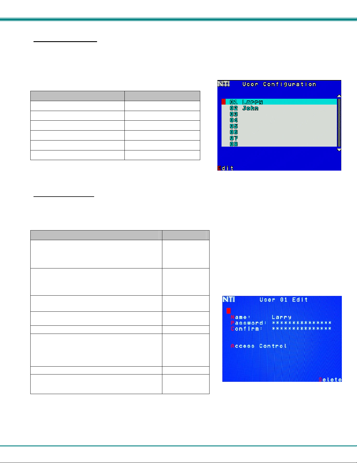
User Configuration
To enter the User Configuration menu: press <U> from the Administration menu. The User Configuration menu can only be
accessed when the administrator is logged-in.
The User Configuration screen lists the users configured to access the UNIMUX. Up to 63 users can be assigne d access.
To assign a user name, password, and port access control, select the user number or an empty record and press <Enter>, <E>,
or click it with the mouse.
Function Keystroke
Select previous user in the list
Select next user in the list
Scroll to previous 8 names
Scroll to next 8 names
Edit account for selected user
Exit and return to previous menu
Figure 29- User Configuration
up arrow
down arrow
Page up
Page down
E
Esc
Edit User Account
The User Account mode (see Figure 30) enables the administrator to:
- add a new user
- remove an existing user
- edit the settings for an existing user
Function Keystroke
Place edit field around the name- enabling it to be
edited
If no name is entered, a default name “userXX”
(where XX is the user number) will be entered
Open an edit field to insert a user password- up to 15
characters in length
If no characters are entered, no password will be
required for that user
Usable characters for Name or Password
(Upper and lower case characters can be used)
Open an edit field to confirm the password by
retyping
Close an edit field
Open access control list for the user, to assign ports
the user will be able to connect to
For new users, by default, no ports are user
accessible unless selected by the administrator
Delete all account information for the selected user
Exit and return to previous menu
Changes made will be saved automatically
N
P
A-Z /0-9 or
Shift + A-Z
C
Enter
A
D
Esc
Figure 30- User Account menu
Note: To change the characters of a name while in the edit field, type th e new characters or use the <Spacebar> to
overwrite the existing characters. Pressing the <Delete> key will have no effect on existing characters and the
<Backspace> key will only work if the cursor is at the end of the edit field. Use the <left arrow>, <right arrow>, <home>
or <end> keys to move the cursor while in editable fields.
25
NTI UNIMUX SINGLE-USER HIGH DENSITY KVM SWITCH
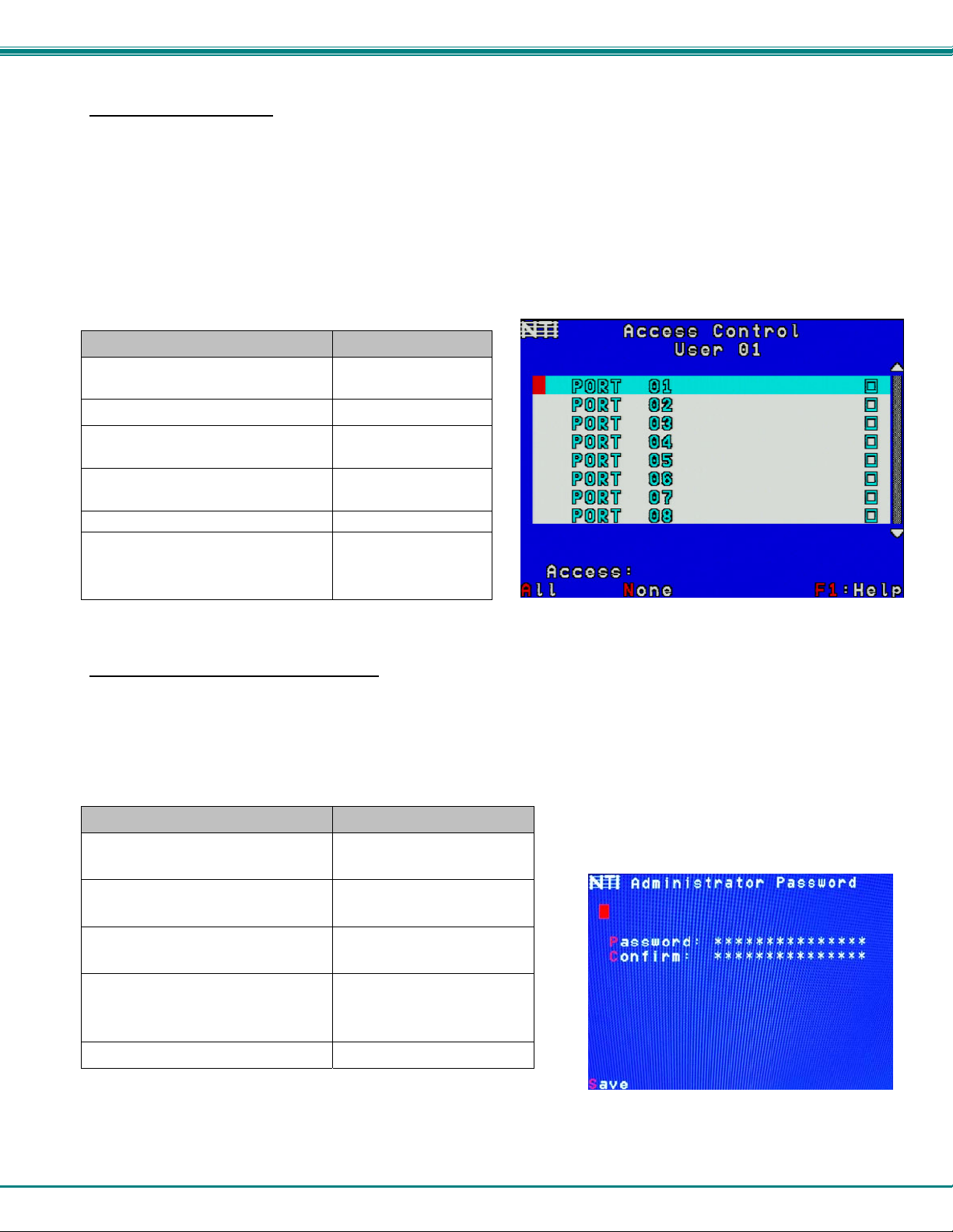
User Access Control
To enter the Access Control list for a user, press A from the User Account screen for that user. From the Access Control list the
administrator can:
• select all ports to have access to
• deselect all ports so that none can be connected to
• select only a limited number of ports to be accessed
The Access Control list is a check list with all the port numbers displayed
• unchecked box = the corresponding port is not in the access list
• checked box = the corresponding port is in the access list
Function Keystroke
Toggle the state of the selected
check box
Select the next or previous port
Quickly place check marks in all
boxes
Quickly remove check marks from all
boxes
Open Help window for this topic
Exit and return to previous menu
Changes made will be saved
automatically
Spacebar
up or down arrow
A
N
F1
Esc
Figure 31- Access Control list
Change Administrator Password
To change the Administrator Password, press <C> from the Administration menu.
The Admin Password menu (see Figure 32) enables the administrator to change his password. Two edit fields are available, one
for password, the other for verify password. The password can be up to 15 characters in length.
Note: The default password for the administrator is “nti”.
Function Keystroke
Switch between Password and
Confirm (password) fields
Add character to password string
or confirm string
Delete previous character in
edited string
Save new password. (The
administrator will be prompted
for a Yes or No confirmation)
Exit and return to previous menu
Figure 32- Administrator password menu
Tab
A-Z, 0-9
(upper or lower case)
Backspace
S
Esc
Note: If the confirmation password does not match the first password entered, the message “INVALID PASSWORD” will
be displayed when you try to save it.
26
NTI UNIMUX SINGLE-USER HIGH DENSITY KVM SWITCH
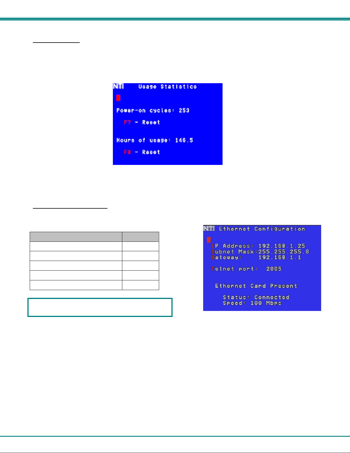
Display Usage
To display usage statistics for the UNIMUX, press <D> from the Administration menu.
The Display Usage page shows the user how many times the UNIMUX has been power cycled and how many total ho urs it has
been powered ON. The counters for these statistics can be reset to 0 by pressing <F7> to reset the number of power cycles or
<F8> to reset the hours of usage.
Figure 33- Usage Statistics Page
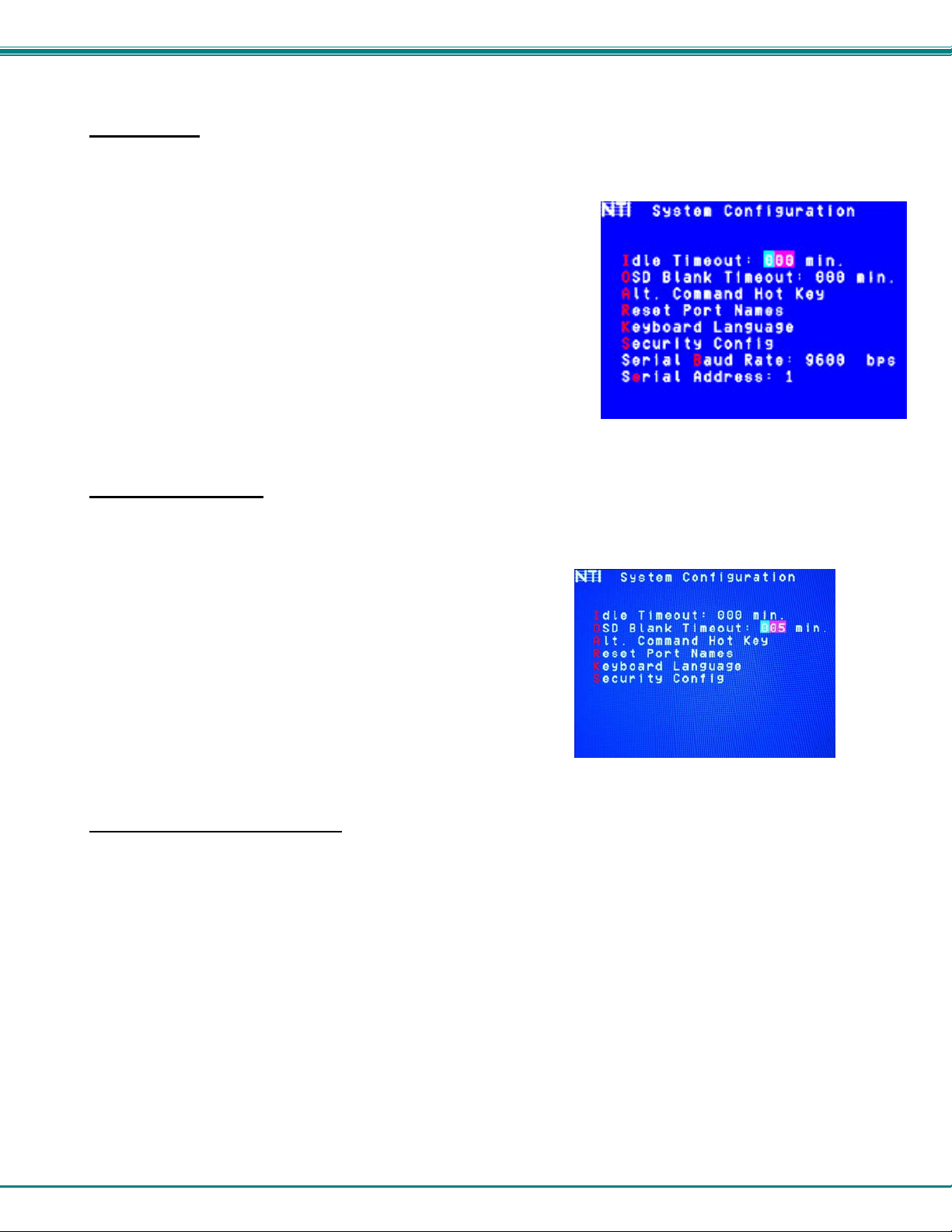
Ethernet Configuration
To configure the ETHERNET port settings on the UNIMUX for controlling the switch via Telnet Interface (page 40), press <E>
from the Administration menu. The default values are shown in Figure 34.
Function Keystroke
Change the IP Address
Change the Subnet Mask
Change the Gateway
Change the port number
Exit and return to previous menu
Network settings can also be changed using the NTI
Discovery Tool. See page 45.
Figure 34- Ethernet Configuration
If the Ethernet feature is not present in the UNIMUX, the message “Ethernet Card Not Present” will appear at the bottom of
this menu in Figure 34.
If the Ethernet port is present but not connected, the message “Ethernet Card Present, Status: Not Connected” will
appear at the bottom of the Ethernet Configuration menu (Figure 34).
I
S
G
T
Esc
Note: The Ethernet port is not available when the CAT5 option is present.
27
NTI UNIMUX SINGLE-USER HIGH DENSITY KVM SWITCH
Idle Timeout
The idle timeout is the amount of time that the user can be idle while in Command Mode before the user is automatically logged
out. The idle timeout can be set to any value from 000 to 255 minutes. A value of 000 will disable it. After the idle timeout
period has elapsed, the login screen will appear.
To change the Idle Timeout setting,
1. press <I> from the System Configuration menu (page 24) to display the
edit field around the value (see Figure 35)
2. enter the desired value (000-255 minutes)
3. press <Enter> to save it and move to the next field
4. press <Esc> to exit the System Configuration menu
Figure 35- Change value of Idle Timeout
OSD Blank Timeout
The OSD Blank Timeout is the amount of time that the user can be idle while in Command Mode before the OSD menu will
disappear. The time period can be set to any value from 000 to 255 minutes. A value of 000 will disable it. After the OSD
disappears when the configured time period has elapsed, the user can make it reappear by either pressing a key on the keyboard
or moving the mouse.
To change the OSD Blank Timeout setting,
1. press <O> from the System Configuration menu to display the
edit field around the value (see Figure 36)
2. enter the desired value (000-255 minutes)
3. press <Enter> to save it and move to the next field
4. press <Esc> to exit the System Configuration menu
Figure 36- Change the value of OSD Blank Timeout
Alternate Command Hot Key
To enable the administrator to assign a key in addition to the <`> (accent/tilde key) to use with <Ctrl> to enter into OSD
Command Mode, an Alternate Command Hot Key option is provided. The default factory setting for this option is <`> (disabling
the option).
To select an Alternate Command Hot Key, press <A> from the System configuration menu (page 23). A window will open and the
administrator will be prompted to press a key. Any key except Ctrl, Shift, Alt, Tab, Esc, or Enter can be used. After pressing the
key, a confirmation message will appear. The administrator should press <Y> (Yes) to validate the key as the Alternate Command
Hot Key, or <N> (No) to select another key.
Pressing <Esc> will return to the Administration Mode menu.
Only the administrator is able to set or change the Alternate Command Hot Key. This function must be set individually for each of
the USB User Device ports on the UNIMUX USB KVM switch.
Note: The Alternated Command Hot Key does not replace the <`> (accen t) key, it just works as another way to enter into
Command Mode. After setting it, the user can enter into Command Mode either with <Ctrl> + <`> or with <Ctrl> +
<Alternate Command Hot Key> combination. To disable it, the administrator should set <`> as the Alternate Command
Hot Key.
28

NTI UNIMUX SINGLE-USER HIGH DENSITY KVM SWITCH
Figure 37- Alternate Command Hot Key selection window
Reset Port names
To erase all configured port names and return them to the factory-default names,
press <R> from the System Configuration menu. After pressing the key, a
confirmation message will appear. The administrator should press <Y> (Yes) to
validate the selection or <N> (No) to cancel it.
Pressing <Esc> will return to the Administration Mode menu.
The switch must be power cycled for the reset to take effect.
Figure 38- Press "R" to reset port names
Select Keyboard Language
To enter the Select Language menu (see Figure 39) press K from the
System Configuration menu described on page 24. Only the
administrator has the Select Language menu option.
The Select Language menu enables the administrator to select a specific
keyboard language (country code) to be used. Typically only SUN CPUs
require a specific country code to be registered at boot up. (For other
types of CPUs this feature may have no effect.) A list of available
languages is displayed and can be scrolled using the mouse (scroll
wheel) and/or <up arrow>, <down arrow>, <Home> and <End> keys.
• To manually program a specific language, select a langua ge and press <Enter> (or click the left mouse button).
• To automatically detect the language of the keyboard, select "AutoDetect" and press <Enter> (or click the left
mouse button) . The list will advance to the actual detected keyboard language and that language will be programmed.
Some keyboards don’t have a country code. In this case the selection will remain in the “AutoDetect” position and the default
country code "00" will be programmed in the UNIMUX. If a specific country code is manually programmed, it will be the country
code for the switch, regardless of the actual country code of the connected keyboard. The programmed country code is saved in
memory and restored each time the UNIMUX is powered-ON. Because the CPUs that use country code (i.e. SUN CPUs) read it
at boot time, it is necessary to boot the CPU(s) after programming the country code.
29
Figure 39- Select Language menu

NTI UNIMUX SINGLE-USER HIGH DENSITY KVM SWITCH
Security Configuration
The UNIMUX can be configured to either have no security enabled such that any user can connect to the UNIMUX, or have
security enabled such that a user must have a login name and password in order to enter Command Mode and make a
connection with an accessible CPU. Only the administrator has access to Security Configuration.
Within Security Configuration, the administrator has three options:
Function Keystroke
Enable security just for the user port
that his currently connected through
Enable Global Security- security
enabled on all user ports
Disable Global Security- security
disabled on all user ports
Return to previous menu
U
E
D
Esc
Figure 40- Security Configuration
If Security is disabled and the user attempts to login to Command Mode
with the command key, the login screen will include the instruction
“Press F1 to Autologin”.
With security disabled, Autologin provides full access to all connected
CPUs and all users except the administrator must use it to login.
When security is enabled, Autologin is not available and the user must
login using the administrator assigned user name and password. The
user will have access to only those CPU ports as configured by the
administrator.
Figure 41- Login screen with security disabled
30

NTI UNIMUX SINGLE-USER HIGH DENSITY KVM SWITCH
Serial Baud Rate
The serial baud rate for the UNIMUX can be changed by pressing <B> from the System Configuration menu. In order to control
the UNIMUX via RS232 (page 34), the baud rate must be set the same as the communication port on the control terminal
attached to the UNIMUX (page 9)
The baud rate value can be set to 115000, 57600, 38400, 19200, 9600, 4800, 2400, or 1200. A data protocol of 8 data bits, no
parity, and 1 stop bit is used for communications. With the edit field highlighted, press the <Left arrow> or <Right arrow>
to change the value of the baud rate.
Note: The baud rate can also be changed from the RS232 Command Protocol (see page 34).
For more on RS232 Control, see page 34.
Figure 42- Adjust Baud Rate
Serial Address
To allow multiple UNIMUXs to be controlled from a single control terminal, the RS232 control interface is designed to allow "daisy
chaining" up to 15 units. Each unit must be assigned a unique address. The unit address for the UNIMUX can be changed by
pressing <E> from the System Configuration menu. With the edit field highlighted, press the <Left arrow> or <Right
arrow> to change the value of the unit address. The address range is 1-15. For more on daisy chaining, see page 34.
Figure 43- Adjust Serial Address
31

NTI UNIMUX SINGLE-USER HIGH DENSITY KVM SWITCH
Keyboard Mapping
The keyboard configuration of each CPU is saved in the UNIMUX switch. For example, if the CPU attached to Port 4 had CAPS
LOCK and NUM LOCK selected the last time that CPU was accessed, then they will automatically be set when that CPU is
accessed again.
Key Equivalents
Using the chart below, find the character needed to be typed on the CPU being accessed, then follow the row across for the
equivalent on the keyboard being used. (See Figure 44 on page 33 for reference.)
USB 101 WINxx MAC
(Apple USB)
L-Ctrl L-Ctrl L-Ctrl L-Ctrl
L-Alt L-Alt L-Option L-Alt
SB+F12 Application SB+F12 Compose
R-Alt R-Alt R-Option Alt-Graph
SB+Alt Windows Logo Command Meta
SB+R Arrow SB+R Arrow Power Suspend
SB = Space Bar
L and R = Left and Right keys when two keys are marked the same on a keyboard.
SUN
Mouse Click Equivalents
To emulate a right button click using Apple 1 button mouse, hold down the Command key ( ) while pressing the mouse
button.
Note: Right mouse button emulation must be enabled (see Settings on page 18) for this to work.
SUN’s 16 Extra Keys
101,WINxx,MAC
Keyboards
SB+F1 Stop (L1) Use the chart to the left to type SUN’s
SB+F2 Again (L2) additional 16 keys using a 101,
SB+F3 Props (L3) WINxx, or MAC (Apple)
SB+F4 Undo (L4) USB keyboard
SB+F5 Front (L5)
SB+F6 Copy (L6)
SB+F7 Open (L7)
SB+F8 Paste (L8)
SB+F9 Find (L9)
SB+F10 Cut (L10)
SB+F11 Help
SB+F12 Compose
SB + Up Arrow Vol +
SB + Down Arrow Vol -
SB + L Arrow Mute
SB + R Arrow Suspend SB= Space Bar
SUN Extras
32
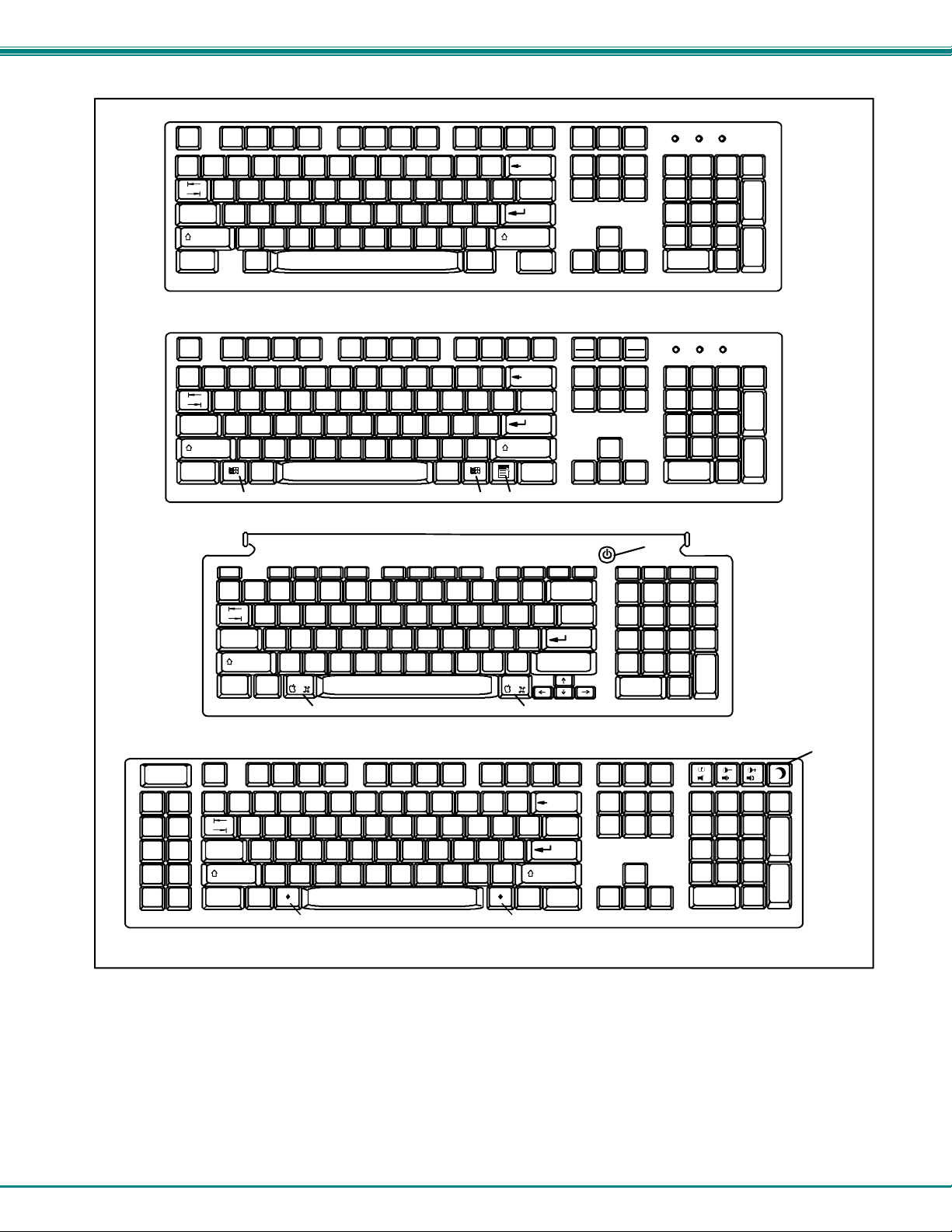
NTI UNIMUX SINGLE-USER HIGH DENSITY KVM SWITCH
Esc
~
`
Tab
Caps Lock
Shift
Ctrl Alt
Alt
Esc
F1 F2 F3 F4 F5 F6 F7 F8 F9 F10 F11 F12
~
`
Tab
Caps Lock
Shift
Ctrl Alt
Typical 101 Keyboard
Alt
Windows Logo Ke y
Windows Keyboard
Help
Stop
Props
Front
Open
Find Cut
Again
Undo
Copy
Paste
esc
~
`
tab
caps Lock
shift
control
Esc
Tab
Caps Lock
Shift
Ctrl Alt
alt
option
Command Key
Apple USB Keyboard
Meta Key Meta Key
SUN USB Keyboard
Backspace
Enter
Shift
Ctrl
Backspace
Enter
Shift
Ctrl
Application KeyWindows Logo Key
Command Key
Backspace
Enter
Shift
Compose
return
Alt
Graph
delete
Print
Screen
SysRq
F12 F11 F9 F10 F8 F7 F6 F5 F4 F3 F2 F1
Scroll
Lock
Num
Lock
Pause
Break
Num
Lock
Power
Button
help home pg up pg dn
num
lock
=/
clear
Num
Lock
Enter
Enter
*
enter
Suspend
key
Enter
Figure 44- Keyboard layouts
33
NTI UNIMUX SINGLE-USER HIGH DENSITY KVM SWITCH
SUN RAY SUPPORT
The UNIMUX fully supports SUN Ray CPUs, however, a lac k of horizontal mouse movement may be experienced. If this occurs,
enable MAC mode (page 24) for the port that the SUN Ray is connected to. This should enable proper mouse movement.
RS232 CONTROL
RS232 enables the UNIMUX to be remotely controlled via RS232. To control the UNIMUX via RS232 the user has three options:
• write a program that runs on a PC using the Command Protocol (page 36)
• use the NTI Switch Control Program (page 37) provided on the CD
• use the SerTest or RMTEST programs (pages 37 and 39) provided on the CD
Remote Connection
The RS232 Interface is designed to meet the RS232C standard and can be controlled from any CPU or other controller with an
RS232 communications port. The pin-out for the RJ45 connector on the unit is as follows:
RS232 (RJ45) CONNECTOR
PIN SIGNAL FUNCTION
1 - No connection
2 - No connection
3 RX+ Receive data (TXD at host)
4 GND Ground
5 - No connection
6 TX+ Transmit data (RXD at host)
7 - No connection
8 - No connection
NOTE: Security must be disabled or user access granted on the port(s) to be selected by RS232 control.
A 5 foot patch cable and two adapters, RJ45-to-DB9 and RJ45-to-DB25, have been provided for connection to most CPUs (see
page 9). To daisy chain multiple units, connect a Matrix-Y-1 cable (sold separately) between the CPU and the first switch, and
between each switch (as shown in Figure 45).
Baud Rate
The baud rate can be changed using the OSD menu (page 34) or from the RS232 commands (page 36) . The baud rate can be
set to 115000, 57600, 38400, 19200, 9600, 4800, 2400, or 1200. A data protocol of 8 data bits, no parity, and 1 stop bit is used
for communications.
Unit Address and Loop Back
To allow multiple units to be controlled from a single host port, the RS232 control interface is designed to allow "daisy chaining" up
to 15 units using an NTI Matrix-Y-1 cable. Connect the Matrix-Y-1 cable between the RJ45-to-DB9 serial adapter and the CPU as
shown in Figure 45. By setting the appropriate unit address (page 34), each unit can be given a unique address (1-15). Then the
unit will only respond to commands on the bus if its address is embedded in the command.
34
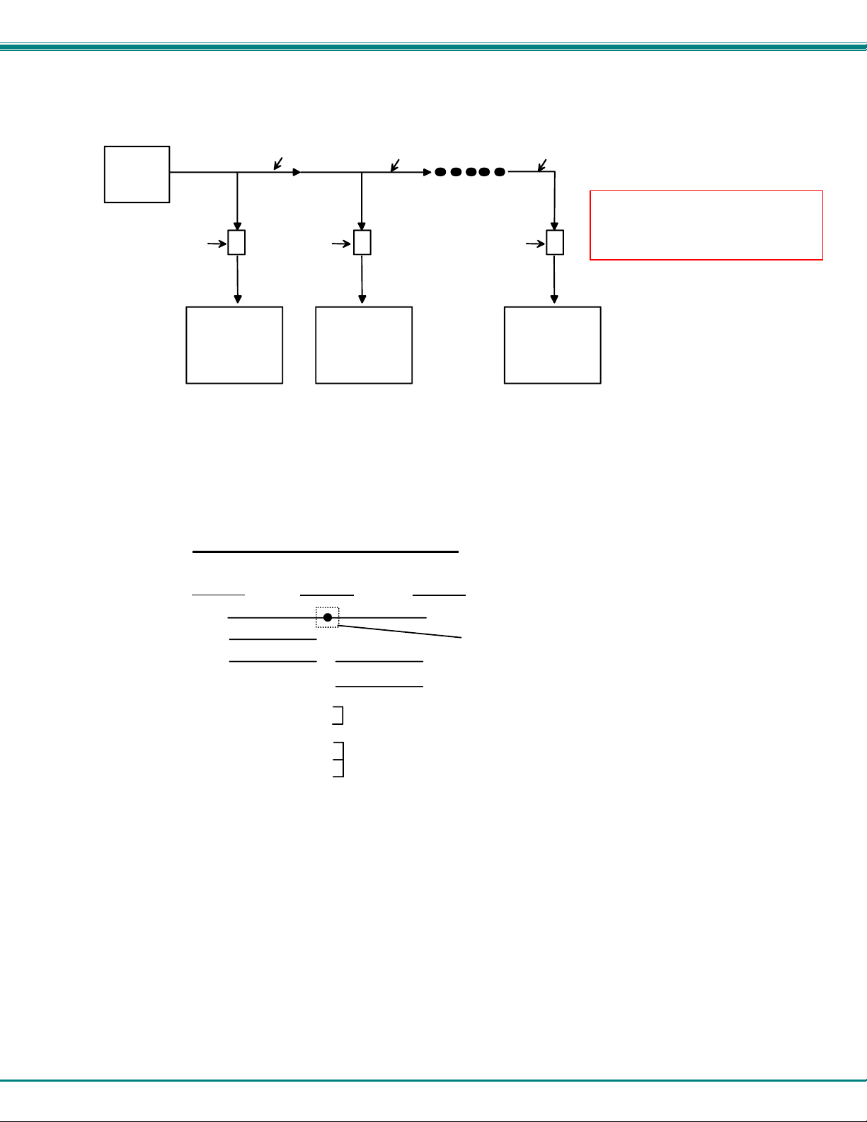
NTI UNIMUX SINGLE-USER HIGH DENSITY KVM SWITCH
exceed 15 feet.
CPU
RS232
Serial Port
RJ45
TO DB9
SERIAL
ADAPTER
First Unit
Matrix-Y-1
RJ45
TO DB9
SERIAL
ADAPTER
CAT5 CABLE CAT5 CABLE CAT5 CABLE
RS232
NTI
SWITCH
SWITCH
Second Unit Last Unit
Matrix-Y-1 Matrix-Y-1
RS232
NTI
RJ45
TO DB9
SERIAL
ADAPTER
SWITCH
Note: The maximum combined
RS232 cable length between the
CPU and any NTI switch cannot
RS232
NTI
Figure 45- RS232 connection with Matrix-Y-1 cable
Figure 46- Pinout of Matrix-Y-1 cable
Wiring Schematic of Matrix-Y-1 cable
9D Female9D Male 9D Male
(Unit #1)
23
33
555
(Source)
(Unit #2)
Not connected to
source connector
22
7
Jumper
8
1
Jumpers
4
6
35

NTI UNIMUX SINGLE-USER HIGH DENSITY KVM SWITCH
RS232 Command Protocol
Host controller commands supported by the unit are defined below.
RS232 Command Protocol Quick Reference
Legend: (All numbers must be two digits)
SW : Switch (01-15) IP : Input Port/CPU (01-MAXINPUTS)
BR : Baud Rate Code <CR>: Carriage Return (Hex 0xD)
OP : Output/User Port
Command String Good Response Description
CS SW,IP,OP *<CR> Connect one User port To CPU port
RO SW,OP *<CR>IP<CR> Read Connection For User Port
CB 00,BR None Change Baud Rate For All Switches
BR = 12 (1200), 24 (2400), 48 (4800), 96 (9600), 19 (19200),
38 (38400), 57 (57600), 11(115000) (9600 is the default)
RV SW,00 *<CR>string\0<CR> Read NTI Version String
RU SW *<CR>IP,OP<CR> Read Unit Size
SS SW,00 *<CR> Disable Autostatus feature (see below)
SS SW,01 *<CR> Enable Autostatus feature (see below)
GM SW,00 *<CR>go SW OP IP<CR>
(all connections)
RP SW,IP *<CR> Refresh Communication with CPU USB port
If the first field is not a known command (as listed above) or SW field is different from the serial address programmed in the switch
memory, the command will be ignored. If the SW field corresponds to the serial address, but the syntax is wrong after this field,
the switch will answer with ?<CR>.
Syntax example:
CS 01,05,01<CR> (insert the space and commas as shown)
which means “At the switch with unit address 01, connect CPU port 05 to user port 01”
The switch will answer with:
∗<CR>
The HEX code representation of example above is:
List all switch User port connections; all User ports to all CPU ports
Byte 1 Byte 2 Byte 3 Byte 4 Byte 5 Byte 6 Byte 7 Byte 8 Byte 9
‘C’
(0x43)
‘S’
(0x53)
Space
(0x20)
Switch – 1st digit
Byte 10 Byte 11 Byte 12
Input –1st digit
(0x30)
Response:
Input –2nd digit
(0x31)
(0x30)
<CR>
(0x0D)
Switch – 2nd digit
(0x31)
WARNING: When using RS232 to control the UNIMUX while a
flash drive is in a transparent USB port (where applicable),
you should eject the USB device within the operating system
at the connected CPU before switching ports using an RS232
command. Otherwise, the flash drive could get corrupted.
(0x2C)
Output – 1st digit
‘,’
(0x30)
Output – 2nd digit
(0x35)
‘,’
(0x2C)
Byte 1 Byte 2
‘∗’
(0x2A)
<CR>
(0x0D)
36

NTI UNIMUX SINGLE-USER HIGH DENSITY KVM SWITCH
Autostatus
When Autostatus is enabled, any output-to-input connection change in the UNIMUX will cause an Autostatus message to be sent
via RS232 to the administrator. The format of the message would be "pc SW,OP:IP<CR>"
Example of an Autostatus message:
pc 01,01:04<CR>
which means "At the switch with unit address 01, the output (01) has changed connection to input 04."
Notes: Message to the administrator will be delayed by any RS232 traffic being received by the switch from the
administrator.
Autostatus must be disabled before using SerTest or the NTI Switch Control Program (below).
By default, Autostatus is disabled and must be manually enabled. Autostatus is also disabled any time the power to the UNIMUX
is interrupted.
NTI Switch Control Program For Windows 9X, NT, 2000, XP, Vista and 7
The NTI Switch Control Program is an easy and powerful graphical program that controls NT I KVM switches through an RS232
interface. The NTI Switch Control Program is included on the CD packaged with the UNIMUX. The NTI Switch Control Program
is downloaded by clicking on the link "Download NTI Switch Control Program" found on the webpage the opens when the CD is
inserted into the CDROM drive.
To install the NTI Switch Control Program after downloading
1. Locate the Setup.exe in the directory the program was downloaded to and double-click on it
Note: In order to use the NTI Switch Control Program to control the UNIMUX, the UNIMUX RS232 port must be set at a
baud rate of 9600 bps (see page 34).
The NTI Switch Control Program performs best on monitors set to a screen resolution of at least 800 X 600. Instruction for using
the NTI Switch Control Program is available by opening "MSCP Help" in the "NTI" program group once the program has been
installed and is open on the screen.
To open "MSCP Help" from the Windows desktop
2. Follow the instructions on the screen
1. Click on START
2. Click on PROGRAMS
3. Click on NTI
4. Click on MSCP Help
37

NTI UNIMUX SINGLE-USER HIGH DENSITY KVM SWITCH
SerTest- RS232 Interface Test Program
This software allows a user to test the functions of an NTI server switch, matrix switch or Multi-user/Multi-platform switch RS232
interface. The program SERTEST along with the NTI Switch Control Program (page 37) is installed from the CD packaged with
this switch. SERTEST generates a main menu with the selections described below:
Main Options
• Matrix Operations
• Ethernet Operations
• Setup Options
• About SerTest
Matrix Operations
Key Selection Description
1) Connect Output/User to an Input/CPU - connect an output to an input
2) Connect All Outputs/Users to an Input/CPU - connect all outputs to an input
3) Connect Audio Output/User to an Input/CPU - connect an output to an input (audio ports only)
4) Connect All Audio Outputs/Users to an Input - connect all outputs to an input (audio ports only)
5) Change Mute Status for Audio Output/User - mute or un-mute the Audio port output
6) Change Volume for Audio Output/User - change Audio port output volume
7) Read Connection for Video Output/User -read the connection of a specific video output
8) Read Connection for Audio Output/User -read the connection of a specific audio output
9) Read Mute and Volume for Audio Output/User - read the volume and the mute status of the specified output (audio
a) Save I/O Connections into Unit Memory -save the connections into switch memory bank
b) Restore I/O Connections from Unit Memory -restore the connections from switch memory bank
c) Change All Uni ts Baud Rate (9600/COM1:) -change RS232 Baud rate of all switches
d) Reset Unit - send a reset command to the switch
e) Reset All Units - send an internal reset command to all switches
f) Read Unit Size - read the switch size (number of inputs and outputs)
g) Read Unit Version/Revision String -read a string containing the switch version, type, and size
h) Save All Units I/O Connections into Units Memory -save the connections into switch memory bank, command for all
i) Restore All Units I/O Connections from Units
Memory
Selections in the "Key" column that are gray are not applicable to this product.
- send commands to the matrix unit.
- set Ethernet connection variables (not applicable to this product)
- set COM port, baud rate, and unit address
- display the program version
ports only)
-the current baud rate and serial port are displayed in parentheses
(This command does not function at this time)
switches
-restore the connections from switch memory bank, command for all
switches
Setup Options
Key Selection Description
1) select Com port current:
(COM1:)
2) select Baud rate current:
(9600)
3) set unit Address current: (1) - select the unit address
For any selection that requires user input, the user is prompted. When commands are sent to the matrix unit, the command string
and matrix unit responses are echoed to the screen. All commands generated by the program are formatted according to the
information provided in sections above. If any transmission problems are detected, an error message is displayed.
Press <Esc> or <Enter> to back out to the main menu and press again to exit.
- select PC serial port
- the current PC serial port is displayed in parentheses
- select PC serial port baud rate
- the current baud rate is displayed in parentheses
- the current address is displayed in parentheses
38

NTI UNIMUX SINGLE-USER HIGH DENSITY KVM SWITCH
RMTEST-RS232 Interface Test Program
This software also allows a user to test the functions of an NTI server switch, matrix switch or Multi-user/Multi-platform switch
RS232 interface. The RMTEST program is automatically loaded when installing the NTI Switch Control Program as described on
page 37. The RMTEST program, located in the NTI program group, generates a main menu with the 3 selections d escribe d
below:
MAIN OPTIONS
1. Matrix Options - send commands to the matrix unit.
2. Setup Options - set COM port, baud rate, and unit address
3. Quit - quit the program
If Matrix Options is selected, the following menu, which has 7 options, is displayed:
MATRIX OPTIONS
1. Reset single unit - reset single matrix to power-up defaults (matrix switch only)
2. Reset all units - reset all daisy chained matrix units (matrix switch only)
3. Change single output - connect an input to one output
4. Change all outputs - connect an input to all outputs
5. Read single output - read which input is connected to an output
6. Read unit size - read how many inputs and outputs the unit has
7. Return to main menu - go back to the MAIN OPTIONS menu
The Setup Options main menu selection only needs to be executed if the switches baud rate or unit address have been changed
from the factory defaults (9600 baud, and unit address = 1). When this option is selected, the following menu, which has 4
options, is displayed:
SETUP OPTIONS
1. Set COM port (default = COM1) - set port to COM1-COM3
2. Set baud rate (default = 9600) - set baud rate (see interface manual for supported baud rates)
3. Set unit address (default = 01) - set the unit address (if multiple units are daisy-chained)
4. Return to main menu - Go back to the MAIN OPTIONS menu
For any selection that requires user input, the user is prompted. When commands are sent to the matrix unit, the command string
and matrix unit responses are echoed to the screen. All commands generated by the program are formatted according to the
information provided in the sections above. If any transmission problems are detected, an error message is displayed.
39

NTI UNIMUX SINGLE-USER HIGH DENSITY KVM SWITCH
TELNET INTERFACE
The UNIMUX can be controlled via Telnet interface by connecting to the UNIMUX through port 2005 (configurable-page 27).
Note: The Telnet Interface is not available when the CAT5 option (page Error! Bookmark not defined.) is present.
The Telnet Interface enables the user to control the switch using a telnet client through an Ethernet connection (page 10). T he
telnet server listens on port 2005. For telnet control using the telnet interface and the current IP address, type the following in a
command shell:
(If default IP address (used in the command below) or port number has been changed (page 27), substitute the current value.)
telnet 192.168.1.25 2005
Use the command set below to control and acquire information from the UNIMUX.
Legend: (All numbers must be two digits)
OP : Output Port (01)
IP : Input Port (01-MAXINPUTS)
<CR> : Carriage Return (Hex 0xD)
NN : Connection configuration reference number (00-99)
Command Summary
Command String Good Response Description
RU<CR>
RO OP<CR>
CS OP,IP<CR>
CA IP<CR> *<CR> Connect all outputs to IP
SS 01<CR> *<CR> Enable auto-status mode
SS 00<CR> *<CR> Disable auto-status mode
SX<CR> See details Examine connections
CC NN<CR> *<CR> Save Connections
RC NN<CR> *<CR> Read (Load) Connections
RP IP<CR> *<CR> Refresh Communication with
XX<CR> *<CR> Close connection
A <CR> (carriage return, 0x0D) is considered to be the end of the command string. If a string exceeds 16 characters, an end of
string will be inserted automatically to avoid buffer overflow. An eventual <LF> (line feed, new line, 0x0A) after a <CR> will be
ignored. A bad string will always be responded to with the ASCII character ‘?’ followed by a <CR>.
ru OP,IP<CR>
pc OP,IP<CR>
*<CR> Connect OP to IP
Read unit size
Read connection for OP
CPU USB port
WARNING: When using Telnet to
control the UNIMUX while a flash
drive is in a transparent USB port
(where applicable), you should eject
the USB device from within the
operating system at the connected
CPU before switching ports using a
Telnet command. Otherwise the
flash drive could get corrupted.
40

NTI UNIMUX SINGLE-USER HIGH DENSITY KVM SWITCH
Command Detail
RU-Read Unit Size
Command:
Byte 1 Byte2 Byte3
‘R’
(0x52)
Response:
‘U’
(0x55)
<CR>
(0x0D)
Byte 1 Byte 2 Byte 3 Byte 4 Byte 5 Byte 6 Byte 7 Byte 8 Byte 9
‘r’
(0x72)
This command will read the size of the unit. The response returns the number of inputs and the number of outputs in two-digit,
ASCII code format. If the numbers are smaller than 10, the 1st digit is ‘0’.
‘u’
(0x75)
Space
(0x20)
Output – 1st digit
(0x30…0x32)
Output-2nd digit
(0x30…0x39)
‘,’
(0x2C)
Input – 1st digit
(0x30…0x32)
Input – 2nd digit
(0x30…0x39)
<CR>
(0x0D)
RO-Read Connection for Output Port
Command:
Byte 1 Byte 2 Byte 3 Byte 4 Byte 5 Byte 6
‘R’
(0x52)
Response:
‘O’
(0x4F)
Space
(0x20)
Byte 1 Byte 2 Byte 3 Byte 4 Byte 5 Byte 6 Byte 7 Byte 8 Byte 9
‘p’
(0x70)
This command will read the connection of an output port. The response returns the output port that is connected to the input port.
‘c’
(0x63)
Space
(0x20)
Output – 1st digit
Output – 1st digit
(0x30…0x32)
(0x30…0x32)
Output-2nd digit
(0x30…0x39)
Output – 2nd digit
(0x30…0x39)
‘,’
(0x2C)
Input – 1st digit
(0x30…0x32)
<CR>
(0x0D)
Input – 2nd digit
(0x30…0x39)
<CR>
(0x0D)
CS- Connect Output Port to Input Port
Command:
Byte 1 Byte 2 Byte 3 Byte 4 Byte 5 Byte 6 Byte 7 Byte 8 Byte 9
‘C’
(0x43)
Response:
‘S’
(0x53)
Space
(0x20)
Output – 1st digit
(0x30…0x32)
Output – 2nd digit
(0x30…0x39)
‘,’
(0x2C)
Byte 1 Byte 2
‘∗’
(0x2A)
This command connects the specified input port to the specified output port.
<CR>
(0x0D)
Input –1st digit
(0x30…0x32)
Input –2nd digit
(0x30…0x39)
<CR>
(0x0D)
41
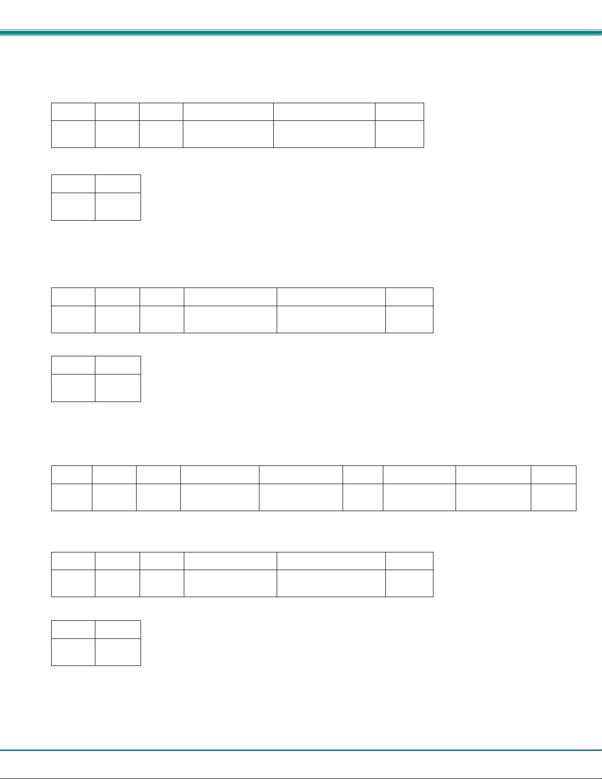
NTI UNIMUX SINGLE-USER HIGH DENSITY KVM SWITCH
CA- Connect All Output Ports to Input Port
Command:
Byte 1 Byte 2 Byte 3 Byte 4 Byte 5 Byte 6
‘C’
(0x43)
Response:
‘A’
(0x41)
Space
(0x20)
Input – 1st digit
(0x30…0x32)
Input - 2nd digit
(0x30…0x39)
<CR>
(0x0D)
Byte 1 Byte 2
‘∗’
(0x2A)
This command connects all output ports to the specified input port.
<CR>
(0x0D)
SS_01- Enable Auto Status Mode
Command:
Byte 1 Byte 2 Byte 3 Byte 4 Byte 5 Byte 6
‘S’
(0x53)
Response:
Byte 1 Byte 2
‘∗’
(0x2A)
Auto status mode is disabled by default whenever the connection is established, and this command must be entered to enable it.
When auto status mode is enabled, a message will be sent whenever an input/output connection changes from any source. The
format of this message is given in the table below. The first two numeric digits are the output port number and the two after the
colon are the number of the input port that is now connected to it.
‘S’
(0x53)
<CR>
(0x0D)
Space
(0x20)
‘0’
(0x30)
‘1’
(0x31)
<CR>
(0x0D)
Byte 1 Byte 2 Byte 3 Byte 4 Byte 5 Byte 6 Byte 7 Byte 8 Byte 9
‘p’
(0x70)
‘c’
(0x63)
Space
(0x20)
Output – 1st digit
(0x30…0x32)
Output – 2nd digit
(0x30…0x39)
‘:’
(0x3A)
Input – 1st digit
(0x30…0x32)
Input – 2nd digit
(0x30…0x39)
<CR>
(0x0D)
SS_00- Disable Auto Status Mode
Command:
Byte 1 Byte 2 Byte 3 Byte 4 Byte 5 Byte 6
‘S’
(0x53)
Response:
Byte 1 Byte 2
‘∗’
(0x2A)
This command disables auto status mode.
‘S’
(0x53)
<CR>
(0x0D)
Space
(0x20)
‘0’
(0x30)
42
‘0’
(0x30)
<CR>
(0x0D)

NTI UNIMUX SINGLE-USER HIGH DENSITY KVM SWITCH
SX- Examine connections
Command:
Byte 1 Byte 2 Byte 3
‘S’
(0x53)
Response:
Multiple lines, one line for each output:
‘X’
(0x58)
<CR>
(0x0D)
Byte 1 Byte 2 Byte 3 Byte 4 Byte 5 Byte 6 Byte 7 Byte 8 Byte 9
‘p’
(0x70)
‘c’
(0x63)
Space
(0x20)
Output – 1st digit
(0x30…0x32)
Output – 2nd digit
(0x30…0x39)
‘:’
(0x3A)
Input – 1st digit
(0x30…0x32)
Input – 2nd digit
(0x30…0x39)
<CR>
(0x0D)
Byte 1 Byte 2 Byte 3 Byte 4 Byte 5 Byte 6 Byte 7 Byte 8 Byte 9
‘p’
(0x70)
Last line:
‘c’
(0x63)
Space
(0x20)
Output – 1st digit
(0x30…0x32)
Output – 2nd digit
(0x30…0x39)
‘:’
(0x3A)
Input – 1st digit
(0x30…0x32)
Input – 2nd digit
(0x30…0x39)
<CR>
(0x0D)
Byte 1 Byte 2
‘∗’
(0x2A)
<CR>
(0x0D)
CC- Save connection configuration into permanent memory at given location
Command:
Byte 1 Byte 2 Byte 3 Byte 4 Byte 5 Byte 6
‘C’
(0x43)
Response:
‘C’
(0x43)
Space
(0x20)
Location – 1st digit
(0x30…0x32)
Location - 2nd digit
(0x30…0x39)
<CR>
(0x0D)
Byte 1 Byte 2
‘∗’
(0x2A)
This command saves the current connection configuration into permanent memory for further use. Up to 100 configurations can
be stored
<CR>
(0x0D)
RC- Read connection configuration from permanent memory at given location
Command:
Byte 1 Byte 2 Byte 3 Byte 4 Byte 5 Byte 6
‘R’
(0x52)
Response:
‘C’
(0x43)
Space
(0x20)
Byte 1 Byte 2
‘∗’
(0x2A)
This command loads the connection configuration from permanent memory into current configuration. Up to 100 configurations
can be stored
<CR>
(0x0D)
Location – 1st digit
(0x30…0x32)
Location - 2nd digit
(0x30…0x39)
<CR>
(0x0D)
43
NTI UNIMUX SINGLE-USER HIGH DENSITY KVM SWITCH
RP- Refresh Communication with CPU USB Port
Command:
Byte 1 Byte 2 Byte 3 Byte 4 Byte 5 Byte 6
‘R’
(0x52)
Response:
‘P’
(0x50)
Space
(0x20)
Input –1st digit
(0x30…0x32)
Input –2nd digit
(0x30…0x39)
<CR>
(0x0D)
Byte 1 Byte 2
‘∗’
(0x2A)
This command will refresh the USB communication with the CPU in cases where the USB port will be put in standby by the
operating system.
<CR>
(0x0D)
Terminate telnet session
Command:
Byte 1 Byte 2 Byte 3
‘X’
(0x58)
Response:
Byte 1 Byte 2
‘∗’
(0x2A)
The unit will respond with ‘*’<CR> and close the connection, terminating the telnet session. The unit is then available for future
connections.
‘X’
(0x58)
<CR>
(0x0D)
<CR>
(0x0D)
44

NTI UNIMUX SINGLE-USER HIGH DENSITY KVM SWITCH
DEVICE DISCOVERY TOOL
In order to easily locate NTI Devices on a network, the NTI Device Discovery Tool may be used. A link to the Discovery Tool is
provided on the web page that appears when you insert the instruction manual CD provided into your CD ROM drive. Either click
on the link or browse the CD to locate the NTIDiscover.jar file. The Discover Tool can be run from the CD or it can be saved
to a location on your PC. Either way, to open it just double-click on the file NTIdiscover.jar . This will open the NTI Device
Discovery Tool.
Note: The Device Discovery Tool requires the Java Runtime Environment (version 6 or later) to operate. A copy of Java
version 6 is provided on the CD and a link to the web page from which it can be downloaded and installed is also on the
CD.
Note: The computer using the Device Discovery Tool and the NTI Device must be connected to the same physical
network in order for the Device Discovery Tool to work. If no devices are found, the message “No Devices Found” will
be displayed.
Tip: If your Windows program asks which program to open the NTIDiscover.jar file with, select the Java program.
Figure 47- Device Discovery Tool
Click on the “Detect NTI Devices” button to start the discovery process. After a short time, the tool will display all NTI devices on
your network, along with their network settings.
How to Use the Device Discovery Tool
To Change a Device’s Settings
on the Enter key, or the Submit button on that row. If the tool discovers more than one device, the settings for all devices can be
changed and you can click on the Submit All button to submit all changes at once.
To Refresh the list of devices, click on the Refresh button.
To Blink the LEDs of the unit, click on the Blink LED button (This feature is not supported on the UNIMUX.) The Blink LED
button will change to a “Blinking….” button. The LEDs of the unit will blink until the Blinking… button is clicked on, or the NTI
Device Discovery Application is closed. The LEDs will automatically cease blinking after 2 hours.
To Stop the LEDs of the unit from blinking, click on the Blinking… button. The Blinking…. button will change to a Blink LED
button.
, within the row of the device whose settings you wish to change, type in a new setting and click
The “Blink LED” button is not
supported on the UNIMUX
45

NTI UNIMUX SINGLE-USER HIGH DENSITY KVM SWITCH
FIRMWARE UPGRADE PROCEDURE
This procedure describes how to upgrade the firmware in this UNIMUX switch. If you are not certain whether this UNIMUX has
the most up-to-date firmware available, see page 51 for instruction on how to determine what versi on the UNIMUX has. All
versions of firmware can be downloaded from the NTI firmware download website at http://www.networktechinc.com/download/d-
srvsw-usbu-hd.html ,
The UNIMUX switch has 3 types of micro-controllers:
1. Main User Controller – there is only one on each UNIMUX and it will be upgraded with a binary file.
¾ For switch models with the Transparent USB ports (i.e. UNIMUX-8HDUT) the file will be named
unimux-suhdt-csx-x.bin (where x-x is the rev number).
¾ For switch models without the Transparent USB ports (i.e. UNIMUX-8HD) the file will be named
unimux-suhd-csx-x.bin (where x-x is the rev number).
Note: Earlier models of UNIMUX that had the extra USB port for specific devices (i.e. UNIMUX-8HDU) will use the
firmware version for models without Transparent USB ports.
2. HID Port Controller – there is one HID Port Controller for each CPU port available o n the switch – it will be upgr aded with an
Intel hex file named unimux-suhd-cpkmx-x.hex. Each CPU port is upgraded independently.
3. Vendor Specific Port C ontroller – there is o ne such controller for each CPU port available on the switch – it will be upgraded
with an Intel hex file named unimux-suhd-cpvdx-x.hex. Each CPU port is upgraded independently.
The UNIMUX firmware has a bootloader which can be used for fi rmware upgrades. The bootloader resi des in a protected area of
Flash memory, so that if the upgrade fails for any reason, the bootloader will still be available to be used to re-program the entire
unit.
Upgrades can be made to the User Controller, HID Port Controller, or V endor Specific Port Controller on an individual basis as
needed. Not all CPU ports must be at the same revision level for the UNIMUX to work, but it is highly recommended that if you
upgrade one CPU port, you upgrade all CPU ports on a switch.
Requirements
¾ CAT5 Patch Cable (supplied with UNIMUX)
¾ RJ45-DB9 or DB25 Adapter (supplied with UNIMUX)
¾ Computer with a Terminal Console (for example, HyperTerminal in Windows, or any similar program able to send files using
Xmodem protocol)
¾ Firmware files for the UNIMUX on the computer with the Terminal Console.
46

NTI UNIMUX SINGLE-USER HIGH DENSITY KVM SWITCH
Preparation For Upgrade
1. With the power to the UNIMUX OFF, connect the computer to the UNIMX as shown in the figure below.
Figure 48- Preparation for firmware upgrade
2. Power ON the computer only. Open the terminal console and apply the following settings to the terminal console for the port
connected to the UNIMUX:
Baud rate: 57600
Data bits: 8
Parity: none
Stop bits: 1
Flow control: none
47

NTI UNIMUX SINGLE-USER HIGH DENSITY KVM SWITCH
Upgrade Procedures
Start the Bootloader
In the HyperTerminal window on the attached computer, press and hold the <Tab> key and power ON the UNIMUX.
The following message (or one similar) will be displayed on the screen:
UNIMUX-HD-NxM Bootloader
Revision: 1.1
Date: 2008/09/11 15:40:16
Copyright (C) Network Technologies Inc.
Press <H> for help…
>
Release the <Tab> key.
The “>” prompt indicates that the bootloader is waitin g for commands. The available commands are composed by sending one
ASCII character. To send a command to the bootloader, type t he key in the terminal window that corresponds to the desired
command. The available commands, listed below, can be viewed by typing <h> or <H> (the Help command) from the keyboard.
Note: Commands can be typed using upper or lower case letters.
Commands:
-------------h, H – Display list of commands
x, X - Exit Bootloader
u, U – Upgrade user controller firmware
p, P – Upgrade HID port controller firmware
v, V – Upgrade vendor specific controller firmware
s, S – Read Checksum of the HID port controller firmware
t, T - Read Checksum of the vendor specific controller firmware
.
48

NTI UNIMUX SINGLE-USER HIGH DENSITY KVM SWITCH
Update the User Controller Firmware
Note: The User Controller Firmware update only needs to be done once, whether the UNIMUX switch is a single-user, or
a multi-user model.
The user controller firmware comes as a file in binary format and has the extension .bin. (i.e. filename.bin). To upgrade the user
controller to this file, press <u> from Terminal window. The following message should appear on the screen:
Erasing flash memory…
Memory successfully erased
Send .bin file using Xmodem protocol..
At this point the binary file unimux-suhd-csx-x.bin must be sent. To do this, from HyperTerminal:
1. go to “Transfer” menu in the Menu Bar of the HyperTerminal window
2. click the item “Send File …”
3. in the dialog box which pops up on the screen, browse for the file to be sent and select it
4. select “Xmodem” from the Protocol drop-down menu
5. press “Send” button
The transmission will start shortly. Wait until the transmission is finished. There will be some pauses during transmission, since
the processor writes blocks of 4KB.
When the transmission is complete, the HyperTerminal window should show the following status message and return to the menu
prompt:
Device successfully programmed!
>
To exit from the bootloader, press <x>.
Update the HID Port Controller Firmware
The HID port controller firmware comes as a file in Intel Hex format and has the extension .hex (i.e. filename.hex). To upgrade
any of HID controllers (there is one per CPU port) with this firmware, press <p> from the terminal window. The following message
should appear on the screen:
Send .hex file using XModem protocol...
At this point, the hex format file unimux-suhd-cpkmx-x.hex has to be sent, using HyperTerminal and the same procedure as
before. When the transmission is done, the following message will be shown in the HyperTerminal window:
File transfer OK!
Please, type the two-digit number of the port to be updated,
<A> to program all or <X> to exit
(the two-digit number should be between 01 and nn,
where nn is the number of available ports):
49

NTI UNIMUX SINGLE-USER HIGH DENSITY KVM SWITCH
To program only one device (CPU port), the corresponding port number must be typed (two-digit number, zero leading, number
between 01 and the last CPU port number, depending on switch size. To program all devices, just press <a>).
The following message will be shown on the screen (it may take about 12 seconds to program each device):
Programming device, please wait...
Device ID: 0x001E
Device successfully programmed!
The bootloader will then ask again for a port number.
To program another port, type the two-digit number of the port,
To exit from this function and the bootloader, press <x>.
If <a> was pressed instead of a single port number, and all devices were programmed, the message above will be re peated for
each port that was programmed. After all are programmed, unless the switch has 32 CPU ports, the following message will be
shown on the screen
Programming device, please wait...
Device ID: 0x0000
Device failed!
Error Code 1
This is shown because the bootloader continues to look for devices until it has found up to 32 (the maximum number of possible
CPU ports a single UNIMUX can have). If it doesn’t find another port, the procedure will fail and discontinu e. On switches with
fewer than 32 ports, this is normal.
To exit from the bootloader, press <x>.
Update the Vendor Specific Port Controller Firmware
Updating the vendor specific port controller firmware is similar to updating the HID port controller firmware (described on page 3).
The only differences are that key <v> is used to enter this command and the hex file to send will be unimux-suhd-cpvdx-x.hex
To exit from the bootloader, press <x>.
50

NTI UNIMUX SINGLE-USER HIGH DENSITY KVM SWITCH
Read the Checksum of HID or Vendor Specific Port Controller Firmware
Reading firmware checksum is useful to determine the version of software running on port controllers. While the firmware revision
for user controller can be found on the UNIMUX splash screen when it is powered-ON, the firmware revision of port controllers is
not displayed anywhere. Reading checksum is an easy way to identify the current firmware revision in your UNIMUX and to
determine if a new firmware revision is available for download.
To read the checksum, type <s> for HID port controllers or <t> for vendor specific port controllers, at the bootloader prompt. The
following message will be displayed:
Please, type the two-digit number of the port to be checked,
<A> to check all or <X> to exit
(the two-digit number should be between 01 and nn,
where nn is the number of available ports):
To read the checksum for only one device, type the number of the port (two digits, leading 0). To read the checksum for all ports
type <a>.
The device ID and the checksum will be displayed in the following format:
Device ID: 0x001E
Device Checksum: 0x3AB1
The checksums for all revisions of UNIMUX firmware can be found on the NTI download webpage at
http://www.networktechinc.com/download/d-srvsw-usbu-hd.html ,
To exit from the bootloader, press <x>.
51
NTI UNIMUX SINGLE-USER HIGH DENSITY KVM SWITCH
SAFETY STATEMENTS
Grounding
These products have protective earth ground terminals and are built with full attention to consumer safety. There must be an uninterruptible safety earth ground between the main power source and the product's power cord or supplied power cord set.
If ever the possibility exists for the grounding protection to have been reduced in any way, disconnect the power supply until the
grounding connection has been fully restored.
Servicing
NTI products are not intended to be serviced in the field and contain no user-serviceabl e parts. In the event repair is needed, all
servicing must be performed by factory trained and authorized service personnel. Only those items specifically ide ntifi ed in this
manual (if any) may be adjusted by the user of this product and adjusted only as instructed in this manual.
CABLES
NTI # DESCRIPTION
HDUSBVEXT-3/6/10/15-MM Connect each CPU to the UNIMUX-UHD with one
HDUSB-3/6-MM Connect each CPU to the UNIMUX-UHD with one- NO VIDEO SUPPORT
USBVEXT-3/6/10 VGA and USB extension
USBVEXT-3/6/10/15-MM VGA and USB interface
USB-AA-5M Connect up to 5 cables in a series for up to 25 additional meters
USB-A+A-5M Improved Active USB 5 meter extension
VEXT-3/6/10/15/25/35/50/75/100 VGA extension through 100 feet
Where:
xx is the length of the cable in feet
MM indicates male-to-male connector
M is the length of the cable in meters
Cables can be purchased from Network Technologies Inc by calling 800-RGB-TECH (800-742-8324) or 330-562-7070.
52
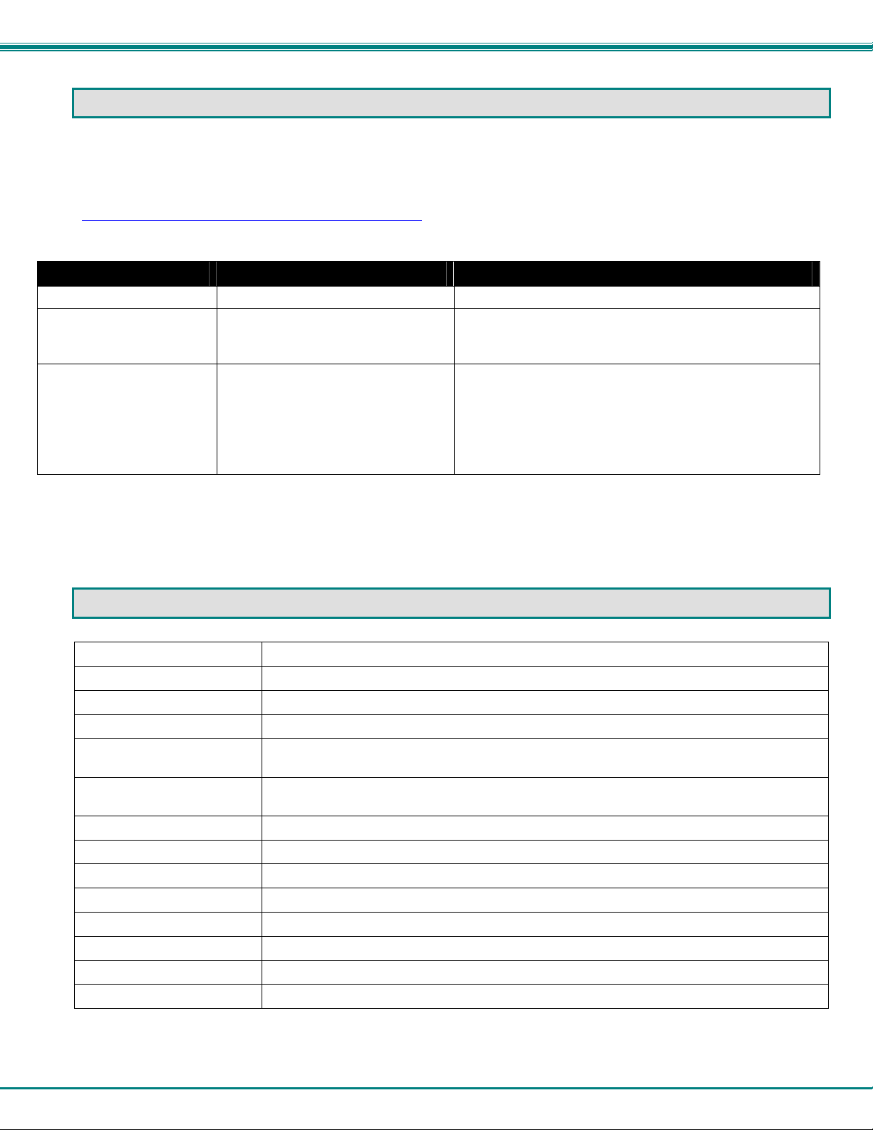
NTI UNIMUX SINGLE-USER HIGH DENSITY KVM SWITCH
TROUBLESHOOTING
Each and every piece of every product produced by Network Technologies Inc is 100% tested to exacting specifications. W e
make every effort to insure trouble-free installation and operation of our products. If problems are experienced w hile installing this
product, please look over the troubleshooting chart below to see if perhaps we can answer any questio ns that arise. If the
answer is not found in the chart, a solution may be found in the knowledgebase on our website at
http://information.networktechinc.com/jive/kbindex.jspa or please call us directly at (800) 742-8324 (800-RGB-TECH) or
(330) 562-7070 and we will be happy to assist in any way we can.
Problem Cause Solution
No mouse or keyboard
No video
No Keyboard and No
Mouse
• Cable connections loose • Check all cables for proper connection
• Loose video cable
• Power to monitor OFF
• Unit is in Command Mode
• USB Lockup
• Check video cable connection
• Make sure monitor is plugged into live outlet and
powered ON
• Press <Esc> key until Command LED on UNIMUX
switch is OFF
• Hot plug the keyboard/mouse in the device ports on the
UNIMUX
• Hot plug the USB cable from the computer
• Power cycle the UNIMUX
SPECIFICATIONS
Video Connectors Female 15HD
Video Resolution 1900 x 1200 (max.)
Video Support SVGA, XGA, VGA, most DVI monitors (when used with NTI DVIF-15HDM adapter)
Video Bandwidth 150 Mhz
USER Keyboard/Mouse
connectors
Mouse and Keyboard
Compatibility
USB Connectors Female USB Type A
USB Compatibility USB low and full speed devices
CPU connectors Female 15HD
CPUs supported Windows USB, SUN USB, MAC USB
RS232 Connector Female RJ45
Power required 110 or 220 VAC @ 50-60 Hz
Fuse Protection 2A, 240VAC
Regulatory approval CE
Female USB Type A
Most USB mice and keyboards
53

NTI UNIMUX SINGLE-USER HIGH DENSITY KVM SWITCH
INDEX
Alternate command hot key, 28
Apple Mouse, 32
autologin, 30
Autostatus, 37
baud rate, 31, 34
Broadcast Mode, 21
cables chart, 52
CAC card reader, 10, 11
Change password, 26
Device Discovery Tool, 45
edit user, 25
ethernet configuration, 27
Ethernet connection, 10
Find Mode, 19
Firmware upgrade, 46
forgot password, 22
front panel control, 13
hot-plug, 4
idle timeout, 28
Installation, 6
Java Runtime Environment, 45
Key Equivalents, 32
keyboard control, 13
limitations, 12
Matrix Switcher's Control Program, 37
navigating OSD menus, 14
OSD, 14
Password and User Name, 22
port configuration, 24
Rack mounting, 5
reset port names, 29, 31
RMTEST, 39
RS232 Command Protocol, 36
RS232 pinout, 34
Scan Mode, 20
security configuration, 30
security enable, 30
Security features, 14
Select Language, 29
SerTest, 38
Settings, 18
Sun's extra keys, 32
system configuration, 24
Telnet Interface, 40
Troubleshoot, 53
usage statistics, 27
USB port, 10, 11
USBVEXT-xx-MM cable, 8
user access control, 26
user configuration, 25
user control methods, 13
WARRANTY INFORMATION
The warranty period on this product (parts and labor) is two (2) years from the date of purchase. Please contact Network
Technologies Inc at (800) 742-8324 (800-RGB-TECH) or (330) 562-7070 or visit our website at http://www.networktechinc.com
for information regarding repairs and/or returns. A return authorization number is required for all repairs/returns.
Man039 Rev 7/23/2015
54
 Loading...