

NTI UNIMUX-USBV-xHD, UNIMUX-USBV-16HDU, UNIMUX-USBV-16HDUC5 Installation And Operation Manual
UNIMUX
TM
Series
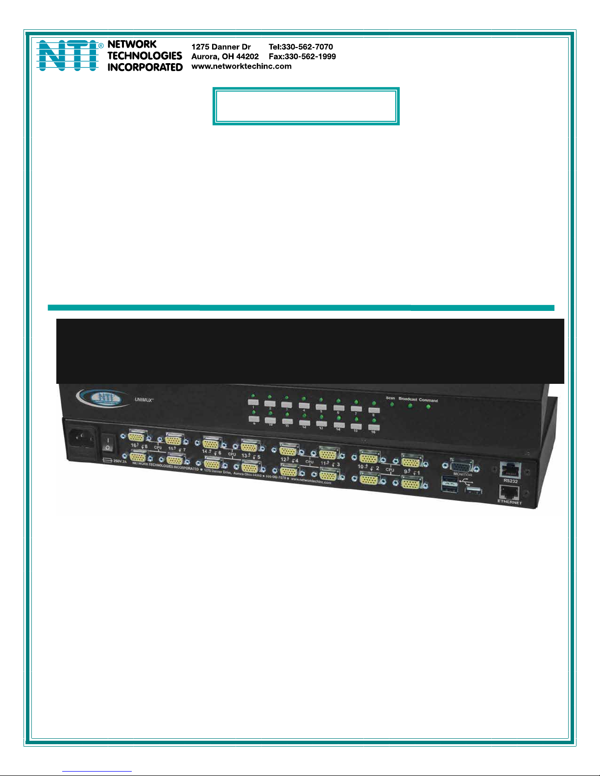
UNIMUX-USBV-xHD
High Density USB KVM Switch
Installation and Operation Manual
MAN039 Rev 10/22/13

TRADEMARK
UNIMUX is a trademark of Network Technologies Inc in the U.S. and other countries.
COPYRIGHT
Copyright © 2000, 2013 by Network Technologies Inc. All rights reserved. No part of this publication may be reproduced,
stored in a retrieval system, or transmitted, in any form or by any means, electronic, mechanical, photocopying, recording,
or otherwise, without the prior written consent of Network Technologies Inc, 1275 Danner Drive, Aurora, Ohio 44202.
CHANGES
The material in this guide is for information only and is subject to change without notice. Network Technologies Inc
reserves the right to make changes in the product design without reservation and without notification to its users.
FIRMWARE VERSION
Main Controller Firmware Version 1.18
Typographic Conventions
Typeface meaning Font Configuration Example
On-screen computer output Courier New-(not bold)
What you type on the computer Courier New-bold
Keyboard Keys to be pressed as
instructed in the body of a
paragraph
Courier New-bold
Surrounded by < >
General
Character Meaning Example
+
-
When "+" is shown between keystrokes, it indicates a chorded
sequence (press and hold the keys consecutively until all keys
in the sequence are pressed)
When "-" is shown between keystrokes, it indicates to press the
keys consecutively (press and release one at a time)
C:>
C:>edit text.bat
“<L>” means press the “L”
<Ctrl>+<`> (accent/tilde key) is a
chorded sequence to enter Command
Mode.
<A>-<S>-<S>-<E> is a sequence of keys
pressed to enable Security Mode
i

TABLE OF CONTENTS
INTRODUCTION...................................................................................................................................................1
MATERIALS...................................................................................................................... ....................................2
Materials Supplied: .........................................................................................................................................2
Materials Not Supplied, but REQUIRED ....................................................................................................... 2
FEATURES AND FUNCTIONS.............................................................................................................................3
Additional Features............................................................................................................................................4
RACK MOUNTING INSTRUCTIONS....................................................................................................................5
To Mount to a Rack ...........................................................................................................................................5
INSTALLATION.....................................................................................................................................................6
RS232 Connection.............................................................................................................................................9
Ethernet Connection........................................................................................................................................10
CAT5 Connection ............................................................................................................................................ 10
USB CAC Card Reader Connection................................................................................................................12
Limitations ...........................................................................................................................................................13
USING THE UNIMUX USB KVM SWITCH......................................................................................................... 14
Basic Operation ...............................................................................................................................................14
Front Panel Control..........................................................................................................................................14
Keyboard Control.............................................................................................................................................14
OSD CONTROL..................................................................................................................................................15
Guidelines for Navigating OSD Menus............................................................................................................15
Security Option................................................................................................................................................15
Initial startup .................................................................................................................................................... 16
User Access Functions.................................................................................................................................... 16
Command Mode ...........................................................................................................................................16
Settings.........................................................................................................................................................18
OSD Settings................................................................................................................................................19
Find Mode..................................................................................................................................................... 19
Help Mode.....................................................................................................................................................20
Scan Mode....................................................................................................................................................20
Broadcast Mode............................................................................................................................................ 21
Normal Mode ................................................................................................................................................21
Security............................................................................................................................................................ 22
Enabling Security.......................................................................................................................................... 22
Password and User Name.........................................................................................................................22
User Login.....................................................................................................................................................23
Additional OSD Modes Available With Security Enabled................................................................................ 23
Administration Menu.....................................................................................................................................23
System Configuration ................................................................................................................................... 24
Port Configuration......................................................................................................................................... 24
User Configuration........................................................................................................................................ 25
Edit User Account.........................................................................................................................................25
User Access Control.....................................................................................................................................26
Change Administrator Password..................................................................................................................26
Display Usage...............................................................................................................................................27
ii

Ethernet Configuration..................................................................................................................................27
Idle Timeout.................................................................................................................................................. 28
OSD Blank Timeout......................................................................................................................................28
Alternate Command Hot Key........................................................................................................................28
Reset Port names......................................................................................................................................... 29
Select Keyboard Language .......................................................................................................................... 29
Security Configuration .................................................................................................................................. 30
Serial Baud Rate........................................................................................................................................... 31
Serial Address...............................................................................................................................................31
Keyboard Mapping...........................................................................................................................................32
Key Equivalents...............................................................................................................................................32
Mouse Click Equivalents..................................................................................................................................32
SUN’s 16 Extra Keys ....................................................................................................................................32
SUN RAY SUPPORT.......................................................................................................................................... 34
RS232 CONTROL...............................................................................................................................................34
Remote Connection......................................................................................................................................34
Baud Rate.................................................................................................................................................. 34
Unit Address and Loop Back.....................................................................................................................34
RS232 Command Protocol.............................................................................................................................. 36
RS232 Command Protocol Quick Reference...............................................................................................36
Autostatus..................................................................................................................................................37
NTI Switch Control Program For Windows 9X, NT, 2000, XP, Vista and 7 .................................................... 37
SerTest- RS232 Interface Test Program.........................................................................................................38
Main Options.................................................................................................................................................38
Matrix Operations..........................................................................................................................................38
Setup Options............................................................................................................................................... 38
RMTEST-RS232 Interface Test Program........................................................................................................39
TELNET INTERFACE......................................................................................................................................... 40
Command Summary.....................................................................................................................................40
Command Detail...........................................................................................................................................41
RU-Read Unit Size.................................................................................................................................... 41
RO-Read Connection for Output Port ....................................................................................................... 41
CS- Connect Output Port to Input Port......................................................................................................41
CA- Connect All Output Ports to Input Port............................................................................................... 42
SS_01- Enable Auto Status Mode............................................................................................................. 42
SS_00- Disable Auto Status Mode............................................................................................................42
SX- Examine connections ......................................................................................................................... 43
CC- Save connection configuration into permanent memory at given location ........................................ 43
RC- Read connection configuration from permanent memory at given location.......................................43
RP- Refresh Communication with CPU USB Port.....................................................................................44
Terminate telnet session ...........................................................................................................................44
REMOTE USER SUPPORT................................................................................................................................45
Command Mode..............................................................................................................................................45
Video Quality Adjustment .............................................................................................................................45
Extended Video Resolution.............................................................................................................................45
FIRMWARE UPGRADE PROCEDURE..............................................................................................................46
Requirements .................................................................................................................................................. 46
Preparation For Upgrade................................................................................................................................. 47
Upgrade Procedures........................................................................................................................................48
iii

Start the Bootloader...................................................................................................................................... 48
Update the User Controller Firmware...........................................................................................................49
Update the HID Port Controller Firmware..................................................................................................... 49
Update the Vendor Specific Port Controller Firmware..................................................................................50
Read the Checksum of HID or Vendor Specific Port Controller Firmware................................................... 51
SAFETY STATEMENTS..................................................................................................................................... 52
CABLES ..............................................................................................................................................................52
CAT5 CABLE WIRING METHOD....................................................................................................................... 52
TROUBLESHOOTING........................................................................................................................................ 53
SPECIFICATIONS .............................................................................................................................................. 53
INDEX..................................................................................................................................................................54
WARRANTY INFORMATION..............................................................................................................................54
TABLE OF FIGURES
Figure 1- Secure rackmount ears to switch.............................................................................................................................5
Figure 2- Secure switch to a rack ...........................................................................................................................................5
Figure 3- Install user monitor.................................................................................................................................................. 6
Figure 4- Install user touch screen monitor.............................................................................................................................6
Figure 5- Install user devices (mouse and keyboard) .............................................................................................................7
Figure 6- Use USB2-AA-5M to extend a device, or a computer.............................................................................................. 7
Figure 7- Connect each CPU using a HDUSBVEXT-xx-MM cable.........................................................................................8
Figure 7- Models without video support, connect using a HDUSB-xx-MM cable.................................................................... 8
Figure 8- Connect cable for RS232 control.............................................................................................................................9
Figure 9- Connect LAN to Ethernet port................................................................................................................................10
Figure 10- Connect CAT5 cable for remote user.................................................................................................................. 10
Figure 11- Connect monitor and devices to ST-C5USBV-R-300 .......................................................................................... 11
Figure 12- CAT5 Enable/Disable button and LEDs............................................................................................................... 11
Figure 13- Connect AC adapter to ST-C5USBV-R-300........................................................................................................12
Figure 14- Install CAC card reader ....................................................................................................................................... 12
Figure 15- Compatible device combinations......................................................................................................................... 13
Figure 16- Command Mode main menu-User....................................................................................................................... 17
Figure 17- Administrator’s main menu..................................................................................................................................18
Figure 18- Settings menu......................................................................................................................................................18
Figure 19- OSD Settings screen........................................................................................................................................... 19
Figure 20- Find Mode in use................................................................................................................................................. 19
Figure 21- Main Menu help screen....................................................................................................................................... 20
Figure 22- Scan List.............................................................................................................................................................. 20
Figure 23- Broadcast List ...................................................................................................................................................... 21
Figure 24- User login screen................................................................................................................................................. 22
Figure 25- Administrator's main menu.................................................................................................................................. 22
Figure 26- User Login screen with........................................................................................................................................23
Figure 27- Administration Mode Menu.................................................................................................................................. 23
Figure 28- System Configuration menu ................................................................................................................................ 24
Figure 29- Port Configuration menu...................................................................................................................................... 24
Figure 30- User Configuration............................................................................................................................................... 25
Figure 31- User Account menu............................................................................................................................................. 25
Figure 32- Access Control list...............................................................................................................................................26
Figure 33- Administrator password menu........................................................................................................................ 26
Figure 34- Usage Statistics Page ......................................................................................................................................... 27
iv

Figure 35- Ethernet Configuration......................................................................................................................................... 27
Figure 36- Change value of Idle Timeout..............................................................................................................................28
Figure 37- Change the value of OSD Blank Timeout............................................................................................................ 28
Figure 38- Alternate Command Hot Key selection window................................................................................................... 29
Figure 39- Press "R" to reset port names .............................................................................................................................29
Figure 40- Select Language menu........................................................................................................................................ 29
Figure 41- Security Configuration ......................................................................................................................................... 30
Figure 42- Login screen with security disabled..................................................................................................................... 30
Figure 43- Adjust Baud Rate.................................................................................................................................................31
Figure 44- Adjust Serial Address.......................................................................................................................................... 31
Figure 45- Keyboard layouts.................................................................................................................................................33
Figure 46- RS232 connection with Matrix-Y-1 cable............................................................................................................. 35
Figure 47- Pinout of Matrix-Y-1 cable ................................................................................................................................... 35
Figure 48- Preparation for firmware upgrade........................................................................................................................ 47
Figure 49- View looking into RJ45 female.............................................................................................................................52
v

NTI UNIMUX SINGLE-USER HIGH DENSITY KVM SWITCH
INTRODUCTION
The UNIMUX-USBV-xHDU High Density USB KVM switch (UNIMUX) allows access to any Windows, MAC, or SUN USB CPUs
from one monitor, USB keyboard and USB mouse (up to 32 CPUs). Internal microprocessor circuitry allows all USB CPUs to be
booted simultaneously without keyboard error. Port selection is accomplished by front panel push buttons or comman ds typed o n
the keyboard. Port lights and status LEDs continuously update on the front panel. Video formats up to 1900X1200 at 150MHz
bandwidth can be displayed from all platforms.
Types of User Input Devices Supported:
• Most USB Keyboards and Mice, corded and wireless
• iKey combo keyboard and touchpad
Types of CPUs Supported:
Any USB CPU supporting USB version 1.0 or above including:
• USB Windows (all)
• USB MAC
• USB SUN
• Linux
Other Devices Supported:
• Touch screen monitors
Tested:
o NEC E222W
o IED IWS-240T-G3
o COMPAQ L2105
o Magic Touch
o Orbit 60380-2
• Smart boards
• Smart Podium monitors (ID422W and ID370 tested)
• CAC Card readers
Options:
Extra USB device port for connection of USB cable from touch screen monitor or CAC card reader- add a “U” to the part number
(i.e. UNIMUX-USBV-xHDU)
Add an RJ45 port for CAT5 extension to remotely locate the user up to 300 feet away using an ST-C5USBV-300-R (Sold
separately)- add a “C5” to the part number (i.e. UNIMUX-USBV-xHDC5 or UNIMUX-USBV-xHDUC5)
High Density switch with only support for USB keyboard and USB mouse. Remove “V” from the model number.
(i.e. UNIMUX-USB-xHD)
1
NTI UNIMUX SINGLE-USER HIGH DENSITY KVM SWITCH
MATERIALS
Materials Supplied:
• NTI UNIMUX-USBV-xHD High Density USB KVM Switch
• IEC Power cord- country specific
• Rackmount kit (4, 8, and 16 port models only)
• CD with pdf file of this manual and RS232 control software
• DB9 Female-to-RJ45 Female adapter
• DB25 Female-to-RJ45 Female adapter
• 5 foot RJ45-to-RJ45 CAT5 patch cable
Materials Not Supplied, but REQUIRED
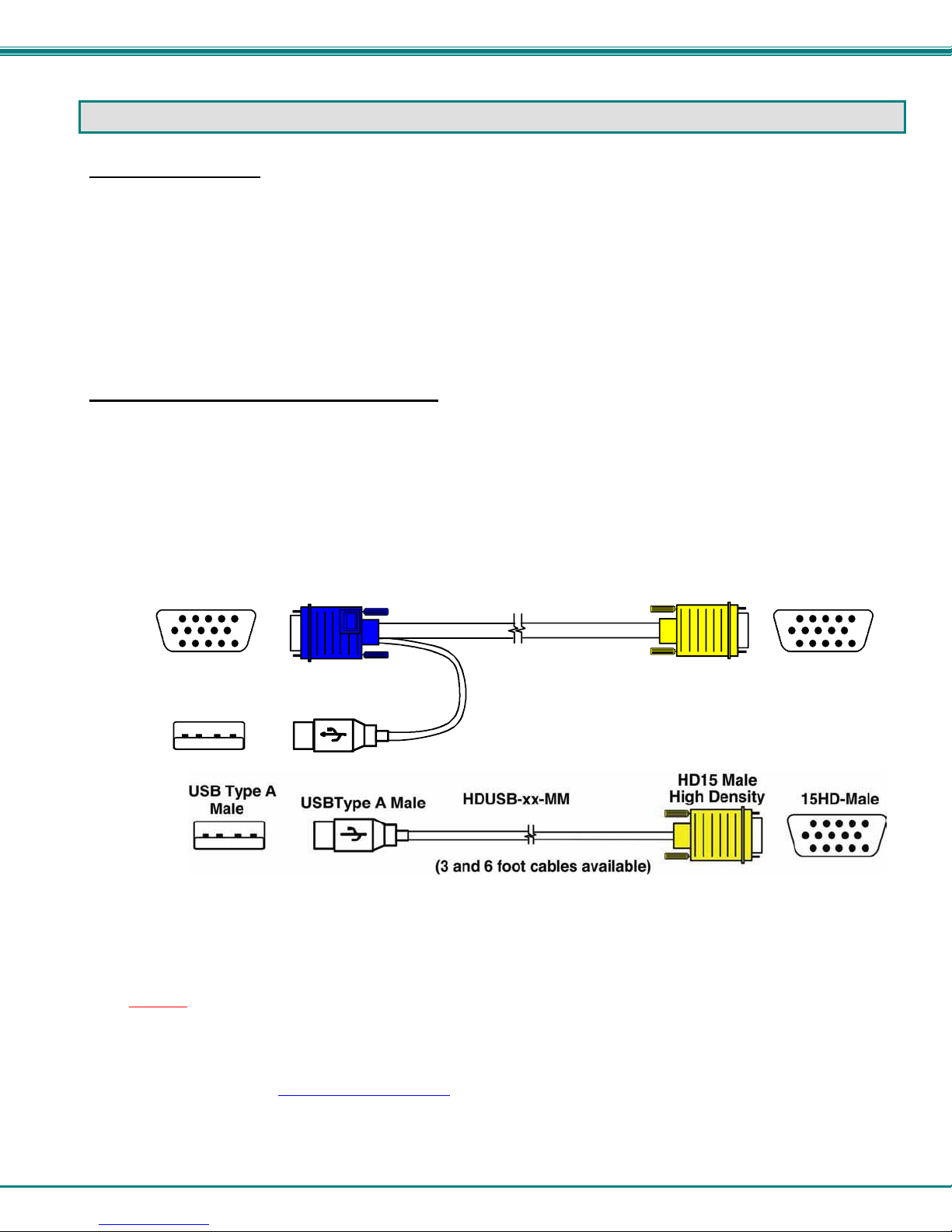
• HDUSBVEXT-xx-MM cable for each CPU being connected to the switch (models with video support)
• HDUSB-3/6-MM -3 or 6 foot cable for each CPU being connected to the switch (models without video support)
Where:
xx is the length of the cable in feet (3,6,10, or 15 feet available)
MM indicates male-to-male connector
Required for models with Remote User support via CAT5:
15HD-Male
USB Type A
Male
HD15 Male
Video
USBType A Male
HDUSBVEXT-xx-MM
(3,6,10 and 15 foot cables available)
HD15 Male
High Density
15HD-Male
• CAT5/5e/6 unshielded twisted-pair cable(s) terminated with RJ45 connectors wired straight thru- pin 1 to pin 1, etc. (see
page 52 for proper EIA/TIA 568 B wiring method)
Note: Shielded
meet CE emission requirements.
Cables can be purchased from Network Technologies Inc by calling 800-RGB-TECH (800-742-8324) or 330-562-7070
or by visiting our website at www.networktechinc.com
See page 52 for some of the available cables.
CAT 5,5e, or 6 cable must be used to connect between the switch and Remote extender unit in order to
.
2
NTI UNIMUX SINGLE-USER HIGH DENSITY KVM SWITCH
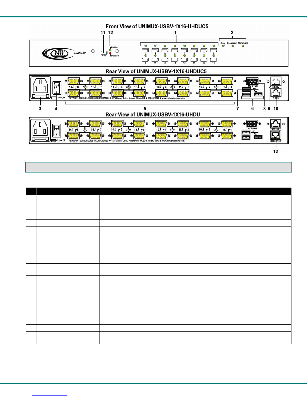
FEATURES AND FUNCTIONS
#
LABEL CONNECTOR/LED DESCRIPTION
1 CPU Numbers
2 Scan,Broadcast,
Command
---- IEC Connector for attachment of power cord
3
---- Power switch for turning the power to the UNIMUX On/Off
4
5 CPU x
6 USB Device Symbol
7 USB Device Symbol
8 MONITOR
9 RS232
10 CAT5
11 CAT5 Button
12 Enable/Disable
13 ETHERNET
Buttons push to manually switch to a specific CPU or change the switch
operating mode
Mode Status LEDs for visual indication of switch operating mode
15HD yellow female
high-density
connectors
USB Type A female
connectors
USB Type A female
connector
15HD female
connectors
RJ45 Female
connector
RJ45 Female
connector
Button pressed to enable or disable the CAT5 port (models with CAT5
Green and Red LED to indicate whether the CAT5 port is enabled for use or disabled.
RJ45 female
connector
for connection of CPU cables for video and device support
for connection of supported user device cables
for USB cable from touch screen monitor or CAC card reader (models
with extra USB device support only)
for connection of user monitor
for attaching RS232 interface cable from a CPU to control the
functions of one or more switches
for connecting a CAT5 cable from an ST-C5USBV-R-300 extender
(models with CAT5 support only)
support only)
for connection to an Ethernet for remote user control via TCP Port
2005 (configurable)
3

NTI UNIMUX SINGLE-USER HIGH DENSITY KVM SWITCH
Additional Features
• Any USB type user device can control any USB CPU (Windows, MAC, and SUN platforms).
• Power cycle circuit control allows the UNIMUX switch to be powered OFF, then ON, at any time without affecting the attached
CPUs. (This assumes that the CPU supports hot plugging.)
• Security features can be enabled.
• A microprocessor is dedicated to each CPU, preventing connected CPUs from locking up.
• Any user device cable can be hot-plugged.
• The front panel LEDs indicate the CPU the user is connected to.
• No dip-switches or jumpers necessary to configure.
• Video formats up to 2048X1536 can be displayed from all platforms.
• Users can control the switch using the On Screen Display (OSD)
• RS232 control allows control of the switch with one CPU serial port. (Windows-based software is provided.)
• NTI Switch Control Program provides easy and powerful graphical control of NTI switches through the RS232 interface.
(Windows only.)
4
NTI UNIMUX SINGLE-USER HIGH DENSITY KVM SWITCH
RACK MOUNTING INSTRUCTIONS
This NTI switch was designed to be mounted to a rack or to sit on a desktop. It includes rackmount ears to make attachment to a
rack easy, and rubber feet to be applied to the bottom of the case if it will instead sit on a flat surface. If this will sit on a flat
surface, simply apply the rubber feet to the bottom of the case in each of the 4 corners.
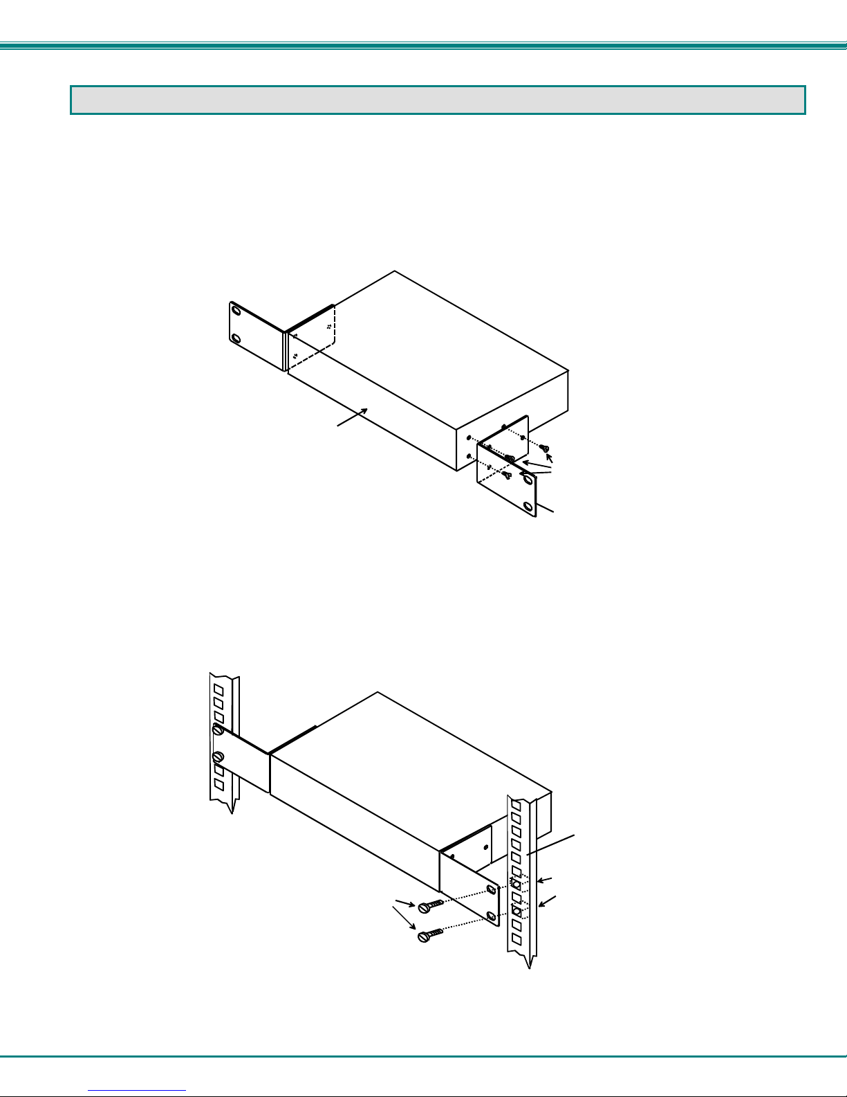
To Mount to a Rack
1. Attach the ears to the switch using the 6-32x3/16" flat Phillips-head screws (6) provided as shown in the illustration be low.
The holes in the ears should line up with pre-threaded holes in the sides of the NTI switch. Tighten the screws securely.
Front of Switch
NTI Switch
6-32x3/16"
Flat Head
Screws
(Provided)
Rackmount Ear
Figure 1- Secure rackmount ears to switch
2. Install 4 captive nuts (not provided) to the rack in locations that line up with the holes in the mounting ear on the NTI switch.
3. Secure the NTI switch to the rack using four 3/16" diameter screws (not provided). Each screw should be of sufficient length
to go completely through the NTI mounting ear, rack frame and fully engage all threads in the captive nut. Be sure to
tighten all mounting screws securely.
4. Attach all cables securely to the switch and where necessary supply adequate means of strain relief for cables.
3/16" Diam eter Screw s
(not provided)
NTI Switch
Rack
Captive Nuts
(not provided)
Figure 2- Secure switch to a rack
5
NTI UNIMUX SINGLE-USER HIGH DENSITY KVM SWITCH
INSTALLATION
It is not necessary to turn OFF power to CPUs or monitors during this installation unless RS232 is going to be connected. All
cables, except for the RS232 cables, may be hot plugged.
If using RS232 Control see RS232 section on page 34 for more information. Observe normal precautions when connecting the
RS232 cables to the CPU. Refer to the owner’s manual for the CPU being connected for precautions, if any.
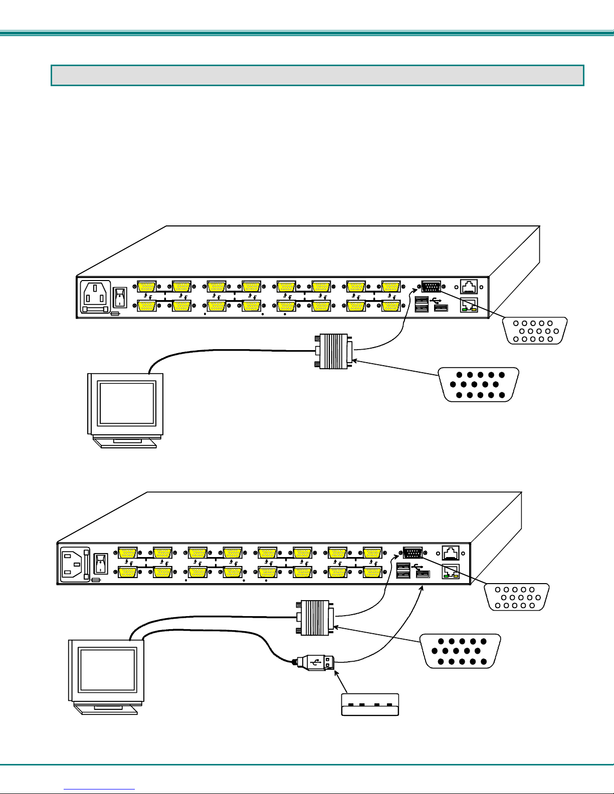
1. Connect the 15HD male cable end from the user monitor to the female black 15HD port marked “MONITOR x” on the rear of
the UNIMUX switch (see Figure 3 ). If a touch screen monitor is being connected (models with touch screen support only),
connect the USB cable from the monitor to any one of the USB type A connectors in the same user device port group
(see Figure 4 ).
16 8 15 7
250V,2A
NETWORK TECH NOLOGIES INC ORPORATED 127 5 Danner Drive, Aurora Ohio 442 02 330-56 2-7070 www.networ ktechi nc.com
14 6
Existing Cable
VGA
Multi-Scan
Monitor
Rear View of UNIMUX-USBV-16H DU
10 2
CPU CPU
13 5
12 4 11 3
CPU CPU
9 1
MONITOR
ETHERNET
15HD Male
Video Connector
RS232
15HD Female
Video Connector
Figure 3- In stall user monitor
Rear View of UNIMUX-USBV-16HDU
16 8 15 7
250V,2A
NETW ORK TE CHNOLOGIES INCORPORATED 1275 Danner Drive, Aurora Ohio 44202 330-562-7070 www.networktechinc.com
14 6
CPU CPU
13 5
12 4 11 3
10 2
CPU CPU
9 1
Existing Cable
VGA
Touch Screen
Monitor
Existing Cable
USB Type A Male
Figure 4- Install user touch screen monitor
MONITOR
ETHERNET
15HD Male
Video Connector
RS232
15HD Female
Video Connector
6
NTI UNIMUX SINGLE-USER HIGH DENSITY KVM SWITCH
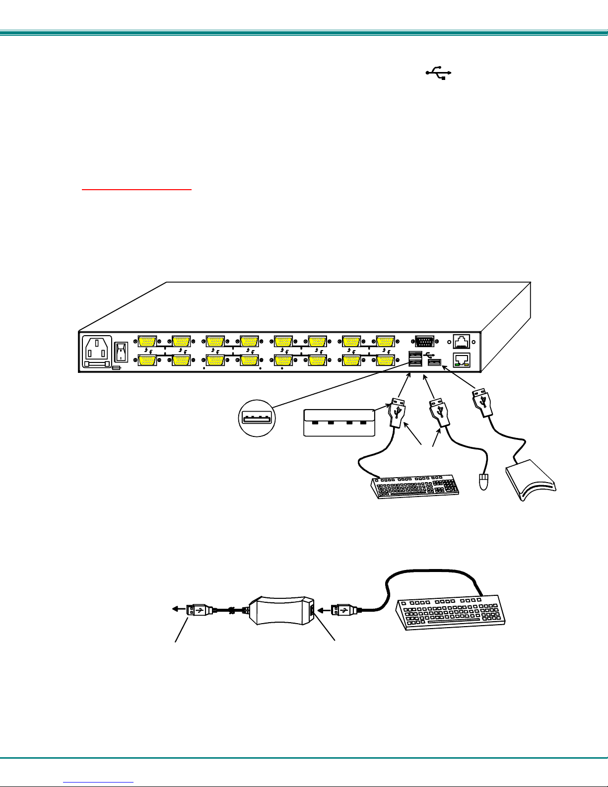
2. Connect the user devices to the USB type A female ports labeled with the USB symbol ( ) on the rear of the UNIMUX
switch (see Figure 5 ).
Note: If there are three (3) USB type A female ports present (models with CAC card reader or touch screen support only),
then the third USB port is available for connection of a USB cable from a touch screen type monitor or CAC card reader.
The USB ports are not device specific, so the mouse, keyboard, and touchscreen mon itor or CAC card reader cable can
be connected to any of the available USB ports present.
Note: If device cables are not long enough to reach the UNIMUX switch, they can be extended up to 20 meters using up
to 4 NTI USB2-AA-5M USB 2.0 Active Extensions (see Figure 6)- purchased separately. Contact yo ur NTI salesperson for
more details by calling (800) 742-8324 (800-RGB-TECH) or (330) 562-7070 or visit our website at
http://www.networktechinc.com
Note: Only one non-HID (Human Interface Device) can be connected to the UNIMUX at a time. (i.e. if a CAC card reader
is present, then a touch screen monitor cannot be used)
16 8 15 7
250V,2A
NETWORK TECHNOLOGIE S INCORPORATED 1275 Danner Drive, Aurora O hio 44202 330-562-7070 www.networktechinc.co m
.
14 6
CPU CPU
13 5
USB Type A Female
Rear View of UN IMUX-USBV- 16HDU
12 4 11 3
USB Type A Male
10 2
CPU CPU
9 1
MONITOR
USB Type A
Male Connector s
USB Keyboard
RS232
ETHERNET
USB
Mouse
CAC
Reader
Figure 5- Install user devices (mouse and keyboard)
TO UNIMUX
SWITCH
USB TYPE A
MALE CONNECTO R
Figure 6- Use USB2-AA-5M to extend a device, or a computer
USB2-AA-5M
FEMALE CONNECTOR
USB TYPE A
7
USB KEYBOARD
NTI UNIMUX SINGLE-USER HIGH DENSITY KVM SWITCH
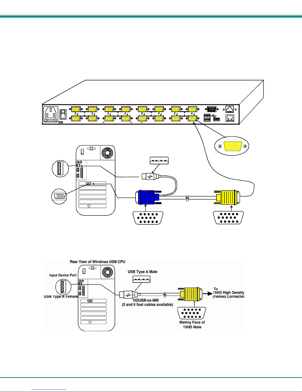
3. For each CPU:
• Connect a USB type A cable end of a HDUSBVEXT-xx-MM cable to a USB type A female user device port on a CPU.
• Connect the 15HD blue male cable end of a HDUSBVEXT-xx-MM cable to the video port of the same CPU.
• Connect the 15HD yellow male cable end of the HDUSBVEXT-xx-MM cable to a yellow “CPU x” port on the UNIMUX
switch. (See Figure 7)
Input Device Port
USB Type A Female
Video Port
15HD Female
Video Connector
16 8 15 7
250V,2A
NETWORK TECHNOLOGIES INCORPORATED 1275 Danner Drive, Aurora Ohio 44202 330-562-7070 www.networktechinc.com
Rear View of Windows USB CPU
14 6
Rear View of UNIMUX-USBV-16HDU
10 2
CPU CPU
13 5
12 4 11 3
USB Type A Male
(3,6,10 and 15 foot cables available)
15HD Male
Video Connector
HDUSBVEXT-xx-MM
CPU CPU
9 1
MONITOR
(Yellow) FemaleCo nn ecto r
RS232
ETHERNET
15HD High Density
15HD Male
Video Connector
Figure 7- Connect each CPU using a HDUSBVEXT-xx-MM cable
Figure 8- Models without video support, connect using a HDUSB-xx-MM cable
8
NTI UNIMUX SINGLE-USER HIGH DENSITY KVM SWITCH
4. Power-up
• The UNIMUX can be powered at any time.
• The CPUs can be powered at any time although if a CPU needs a keyboard and/or mouse at power-ON it should be powered
after connecting to and powering-ON the UNIMUX.
• USB input devices (keyboard and mouse) can be hot plugged to and from the UNIMUX at any time.
Note: The order in which the CPUs and switch are powered up does not matter. A power strip can be used.
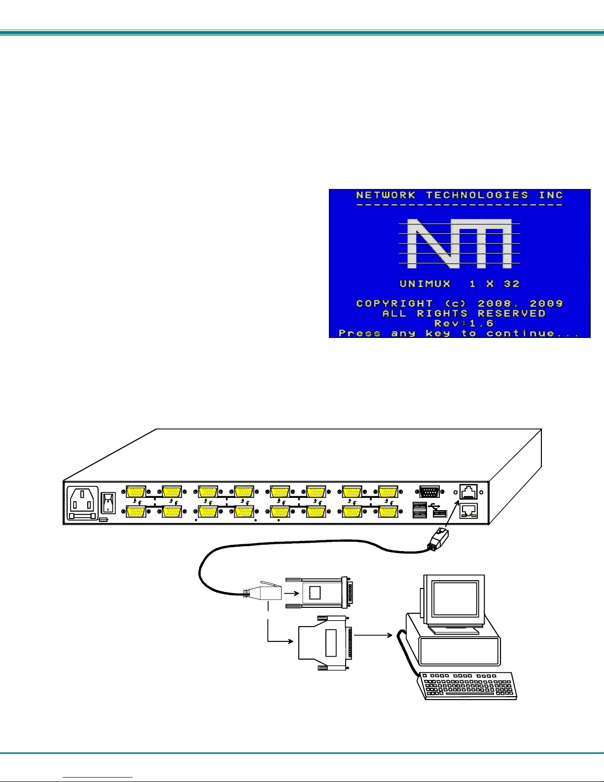
Immediately after powering ON the UNIMUX, the following splash screen will appear on the monitor if the OSD option is built into
the switch:
If the security option is enabled (see page 15 for details on the
"Security Option"), when the UNIMUX is powered up the user will
be prompted for a username and password to continue. If the
security option is not enabled the monitor will display the desktop
image for the connected CPU and the user can continue with
normal operation of the connected CPU.
RS232 Connection
If RS232 control will be used, connect one end of the CAT5 patch cable (supplied) to the port labeled “RS232” o n the rear of the
UNIMUX. Plug the other end of the CAT5 cable into either the RJ45-to-DB9 or RJ45-to-DB25 adapter supplied, and connect the
adapter to the RS232 port on the control terminal. Follow the instruction under “RS232 Control” on page 34 for config uration and
use of the RS232 control feature.
16 8 15 7
14 6
250V,2A
NETWORK TECHNOLOGIES INCORPORATED 1275 Danner D rive, A urora Ohio 44202 330-562-7070 www.networktech inc.com
CAT5 Patch Cable
(supplied)
Rear View of UNIMUX-USBV- 16HDU
10 2
CPU CPU
13 5
12 4 11 3
RJ45-to-DB9 Adapter
(supplied)
or
RJ45-to-DB25 Adapter
(supplied)
CPU CPU
9 1
MONITOR
RS232
ETHERNET
Contro l Te r m inal
VGA
Multi-Scan
Monitor
Figure 9- Connect cable for RS232 control
9
NTI UNIMUX SINGLE-USER HIGH DENSITY KVM SWITCH
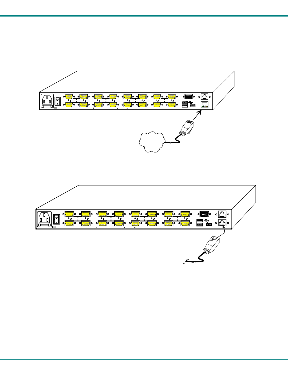
Ethernet Connection
If the Telnet Interface will be used (page 40), and Ethernet connection to the Local Area Network (LAN) must be made using
CAT5 cable with RJ45 connectors attached. Wiring between the connectors should be straight thru (pin 1 to pin 1, pin 2 to pin 2,
etc.). Connect a CAT5 cable between the port labeled “ETHERNET” on the rear of the UNIMUX and the LAN. (This port is not
present when the CAT5 option is present.)
16 8 15 7
250V,2A
NETWORK TECHNOLOGIES INCORPORATED 1275 Danner Drive, Aurora Ohio 44202 330-562-7070 www.networktechinc.com
14 6
Rear View of UNIMUX-USBV-16HDU
10 2
CPU CPU
13 5
12 4 11 3
LAN
CPU CPU
9 1
RJ45-male
connector
MONITOR
RS232
ETHERNET
Figure 10- Connect LAN to Ethernet port
CAT5 Connection
If the CAT5 extender option is present, a CAT5 cable up to 300 feet long can be connected between the “CAT5” port on the
UNIMUX and an ST-C5USBV-R-300 extender Remote Unit (sold separately).
16 8 15 7
250V,2A
NETWORK TECHNOL OGIES INCORPORATED 1275 Danner Drive, Aurora Ohio 44202 330-562-7070 ww w.networktechinc.com
14 6
Figure 11- Connect CAT5 cable for remote user
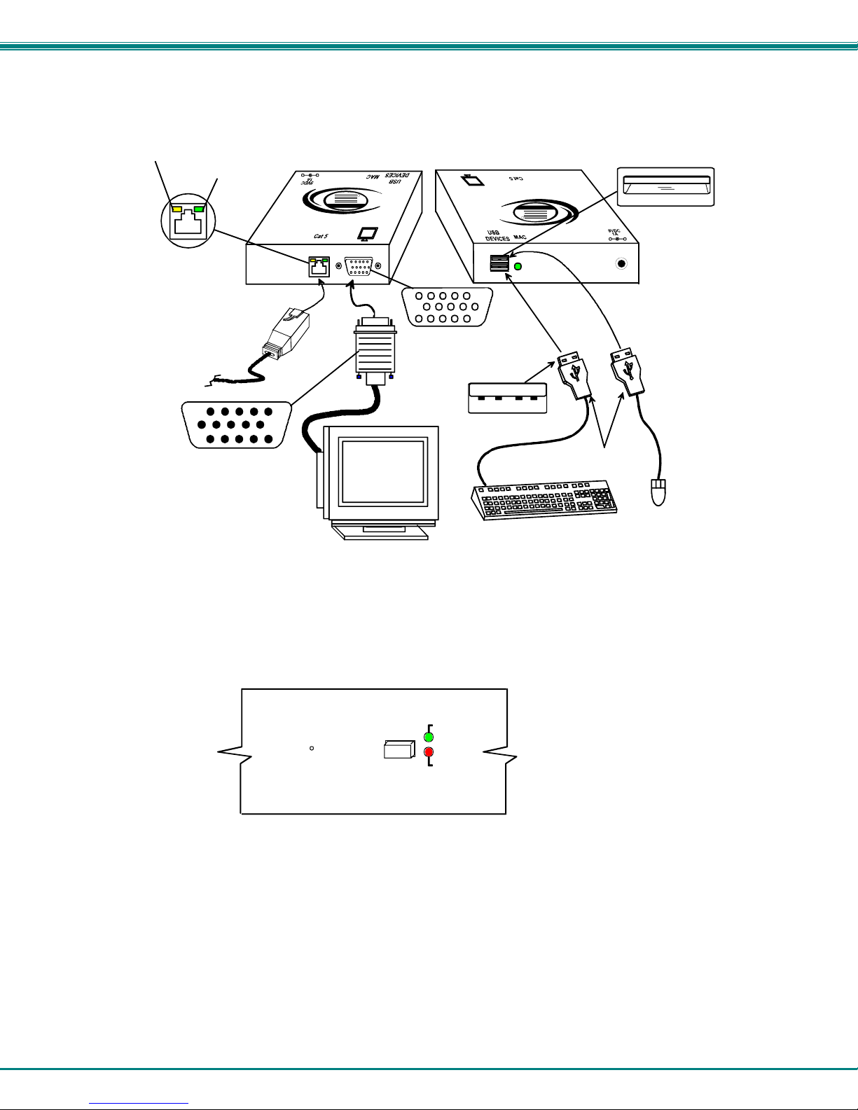
1. Position the ST-C5USBV-R-300 such that the CAT5 cable, the monitor cable, the keyboard and mouse, and the AC adapter
power connector can each reach the ST-C5USBV-R-300 comfortably.
2. Connect the monitor cable to the 15HD female VIDEO port on the ST-C5USBV-R-300. (See Figure 12)
3. Connect the devices to the ST-C5USBV-R-300.
a. Connect the USB keyboard cable to one of the USB Type A female ports labeled "USB DEVICES" on the back
of the ST-C5USBV-R-300. (Either one will work.)
b. Connect the USB mouse cable to the remaining USB Type A female port on the back of the ST-C5USBV-R-
300.
Rear View of UNIMUX-USB V-16HDUC5
10 2
CPU CPU
13 5
12 4 11 3
CPU CPU
9 1
CAT5 Cable to
ST-C5U SBV-R-3 00
Remote Unit
MONITOR
RS232
CAT5
10
NTI UNIMUX SINGLE-USER HIGH DENSITY KVM SWITCH
Yellow Communicatio n LED
Green Power LED
ST-C5USBV-R-300 Remote Unit
(Front View)
-
+
R
NTI
Network Technologies Inc
USB
XTENDEX
CAT5 Cable to
UNIMUX "CAT5"
15HD male
Video Connector
Multi-Scan
15HD Female
Video Connector
USB Type A male
VGA
Monitor
(Rear View)
USB
R
USB Keyboard
USB Type A Female
XTENDEX
Network Technologies Inc
NTI
+
-
USB Type A
male connectors
Mouse
USB
Figure 12- Connect monitor and devices to ST-C5USBV-R-300
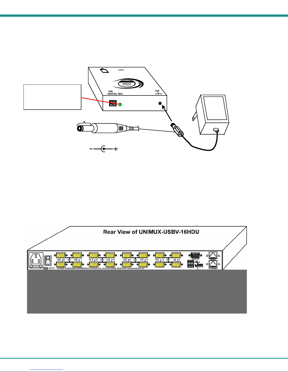
4. Plug the power cord from the monitor(s) into a power outlet.
5. Connect the AC adapter power connector to the 9VDC port on the Remote Units and plug it into a power outlet. The “Power”
LED (Green) on the CAT5 connector of the Remote Unit should illuminate, indicating that a proper power connection has
been made.
6. Press the “CAT5” button on the front of the UNIMUX so that the “CAT5” option will be enabled. The green “Enable” LED
should flash, indicating proper communication with the Remote Unit.
(From front of UNIMUX-USBV-xHDUC5)
UNIMUX
R
Cat5
Enabled
Disabled
Figure 13- CAT5 Enable/Disable button and LEDs
11
NTI UNIMUX SINGLE-USER HIGH DENSITY KVM SWITCH
6. Turn ON the monitor. The monitor should have the same image on it as the monitor directly connected to the UNIMUX.
The yellow communication LED on the Remote Unit (see Figure 12) should blink indicating there is proper communication
with the UNIMUX.
While connected to the
UNIMUX and powered
ON, the MAC LED will
remain on at all times.
Barrel
Power Connector
9VDC @ 1.0A OUTPUT
(Outside
barrel)
2.1 mm x 5.5 mm Female
XTENDEX
USB
Network Technologies Inc
NTI
R
(Rear View)
(Inside
barrel)
ST-C5USBV-R-300
Remote Unit
-
+
9 VDC
Adapter
ADAPTER
Figure 14- Connect AC adapter to ST-C5USBV-R-300
USB CAC Card Reader Connection
If the UNIMUX you have purchased includes the extra USB port option (UNIMUX-USBV-xHDU), then it supports the connection of
a CAC card reader. When used, the CAC card reader will connect to the PC attached to the selected “CPUx” port.
Figure 15- Install CAC card reader
12
 Loading...