

UNIMUX
TM
Series
UNIMUX-nXm-UHD
High Density VGA USB KVM Matrix Switch
Installation and Operation Manual
MAN076 Rev 4/7/14

TRADEMARK
UNIMUX is a trademark of Network Technologies Inc in the U.S. and other countries.
COPYRIGHT
Copyright © 2002, 2014 by Network Technologies Inc. All rights reserved. No part of this publication may be reproduced,
stored in a retrieval system, or transmitted, in any form or by any means, electronic, mechanical, photocopying, recording,
or otherwise, without the prior written consent of Network Technologies Inc, 1275 Danner Drive, Aurora, Ohio 44202.
CHANGES
The material in this guide is for information only and is subject to change without notice. Network Technologies Inc
reserves the right to make changes in the product design without reservation and without notification to its users.
FIRMWARE VERSION
Main Controller Firmware Version 1.23
Typographic Conventions
Typeface meaning Font Configuration Example
On-screen computer output Courier New-(not bold)
What you type on the computer Courier New-bold
Keyboard Keys to be pressed as
instructed in the body of a
paragraph
Courier New-bold
Surrounded by < >
General
Character Meaning Example
+
-
When "+" is shown between keystrokes, it indicates a chorded
sequence (press and hold the keys consecutively until all keys
in the sequence are pressed)
When "-" is shown between keystrokes, it indicates to press the
keys consecutively (press and release one at a time)
C:>
C:>edit text.bat
“<L>” means press the “L”
<Ctrl>+<`> (accent/tilde key) is a
chorded sequence to enter Command
Mode.
<A>-<S>-<S>-<E> is a sequence of keys
pressed to enable Security Mode
i

TABLE OF CONTENTS
INTRODUCTION...................................................................................................................................................1
Definitions..........................................................................................................................................................1
Compatibility......................................................................................................................................................1
ORDERING INFORMATION.................................................................................................................................2
MATERIALS..........................................................................................................................................................3
Materials Supplied: .........................................................................................................................................3
Materials Not Supplied, but REQUIRED ....................................................................................................... 3
FEATURES AND FUNCTIONS.............................................................................................................................4
Additional Features............................................................................................................................................5
RACK MOUNTING INSTRUCTIONS....................................................................................................................6
INSTALLATION.....................................................................................................................................................7
RS232 Connection...........................................................................................................................................11
CAT5 Connection ............................................................................................................................................ 11
Ethernet Connection........................................................................................................................................13
Remote CPU Access.......................................................................................................................................14
No-Video Models............................................................................................................................................. 15
Limitations........................................................................................................................................................ 16
USING THE NTI UNIMUX USB KVM SWITCH.................................................................................................. 17
Basic Operation ...............................................................................................................................................17
Keypad Control................................................................................................................................................17
OSD CONTROL..................................................................................................................................................18
Guidelines for Navigating OSD Menus............................................................................................................18
Security Option................................................................................................................................................18
Initial startup .................................................................................................................................................... 19
User Access Functions.................................................................................................................................... 19
Command Mode ...........................................................................................................................................19
Settings.........................................................................................................................................................21
OSD Settings................................................................................................................................................ 22
Find Mode..................................................................................................................................................... 22
Help Mode.....................................................................................................................................................22
Scan Mode....................................................................................................................................................23
Broadcast Mode............................................................................................................................................ 24
Sharing Mode................................................................................................................................................24
Normal Mode ................................................................................................................................................24
F3- Display Information....................................................................................................................................25
Security............................................................................................................................................................ 26
Enabling Security.......................................................................................................................................... 26
Password and User Name.........................................................................................................................26
User Login.....................................................................................................................................................27
Additional OSD Modes Available With Security Enabled................................................................................ 27
Administration Menu.....................................................................................................................................27
System Configuration ................................................................................................................................... 28
Port Configuration......................................................................................................................................... 28
User Configuration........................................................................................................................................ 29
ii

Edit User Account.........................................................................................................................................29
User Access Control.....................................................................................................................................30
Change Administrator Password..................................................................................................................30
Display Usage...............................................................................................................................................31
Ethernet Configuration..................................................................................................................................31
Idle Timeout.................................................................................................................................................. 31
OSD Blank Timeout......................................................................................................................................32
Alternate Command Hot Key........................................................................................................................32
Reset Port names......................................................................................................................................... 32
Select Keyboard Language .......................................................................................................................... 33
Security Configuration .................................................................................................................................. 33
Serial Baud Rate........................................................................................................................................... 34
Serial Address...............................................................................................................................................35
Keyboard Mapping...........................................................................................................................................36
Key Equivalents...............................................................................................................................................36
Mouse Click Equivalents..................................................................................................................................36
SUN’s 16 Extra Keys ....................................................................................................................................36
RS232 CONTROL...............................................................................................................................................38
Remote Connection......................................................................................................................................38
Baud Rate.................................................................................................................................................. 38
Unit Address and Loop Back.....................................................................................................................38
RS232 Command Protocol.............................................................................................................................. 40
RS232 Command Protocol Quick Reference...............................................................................................40
Autostatus..................................................................................................................................................41
Matrix Switcher's Control Program For Windows 9X, NT, 2000, XP, Vista and 7........................................... 41
SerTest- RS232 Interface Test Program.........................................................................................................42
Main Options.................................................................................................................................................42
Matrix Operations..........................................................................................................................................42
Setup Options............................................................................................................................................... 42
RMTEST-RS232 Interface Test Program........................................................................................................43
TELNET INTERFACE......................................................................................................................................... 44
Command Summary.....................................................................................................................................44
Command Detail...........................................................................................................................................45
RU-Read Unit Size.................................................................................................................................... 45
RO-Read Connection for Output Port ....................................................................................................... 45
CS- Connect Output Port to Input Port......................................................................................................45
CA- Connect All Output Ports to Input Port............................................................................................... 46
SS_01- Enable Auto Status Mode............................................................................................................. 46
SS_00- Disable Auto Status Mode............................................................................................................46
SX- Examine connections ......................................................................................................................... 47
CC- Save connection configuration into permanent memory at given location ........................................ 47
RC- Read connection configuration from permanent memory at given location.......................................47
RP- Refresh Communication with CPU USB Port.....................................................................................48
Terminate telnet session ...........................................................................................................................48
DEVICE DISCOVERY TOOL.............................................................................................................................. 49
How to Use the Device Discovery Tool........................................................................................................... 49
CASCADING.......................................................................................................................................................50
Limitations........................................................................................................................................................ 50
Cable Connections .......................................................................................................................................... 51
iii

Operating Cascaded Switches........................................................................................................................53
SUN RAY SUPPORT.......................................................................................................................................... 53
REMOTE USER SUPPORT VIA CAT5 .............................................................................................................. 54
Command Mode.............................................................................................................................................. 54
Video Quality Adjustment .............................................................................................................................54
Extended Video Resolution.............................................................................................................................54
FIRMWARE UPGRADE PROCEDURE..............................................................................................................55
Requirements .................................................................................................................................................. 55
Preparation For Upgrade................................................................................................................................. 56
Upgrade Procedures........................................................................................................................................57
Start the Bootloader...................................................................................................................................... 57
Update the User Controller Firmware...........................................................................................................58
Update the HID Port Controller Firmware..................................................................................................... 58
Update the Vendor Specific Port Controller Firmware..................................................................................59
Read the Checksum of HID or Vendor Specific Port Controller Firmware................................................... 60
SAFETY STATEMENTS..................................................................................................................................... 61
CABLES ..............................................................................................................................................................61
INTERCONNECTION CABLE WIRING METHOD .............................................................................................61
TROUBLESHOOTING........................................................................................................................................ 62
SPECIFICATIONS .............................................................................................................................................. 62
INDEX..................................................................................................................................................................63
WARRANTY INFORMATION..............................................................................................................................63
Figure 1- Mount Switch in a Rack........................................................................................................................................... 6
Figure 2- Install user monitor(s).............................................................................................................................................. 7
Figure 3- Install user touch screen monitor.............................................................................................................................7
Figure 4- Install user devices (mouse and keyboard) .............................................................................................................8
Figure 5- Use USB2-AA-5M to extend a device, or a computer.............................................................................................. 8
Figure 6- Connect each CPU using a HDUSBVEXT-xx-MM cable.........................................................................................9
Figure 7- Connect each CPU using a HDUSB-xx-MM cable .................................................................................................. 9
Figure 8- Connect cable for RS232 control...........................................................................................................................11
Figure 9- Connect CAT5 cable for remote user.................................................................................................................... 11
Figure 10- Connect monitor and devices to ST-C5USBV-R-300 .......................................................................................... 12
Figure 11- Connect LAN to Ethernet port..............................................................................................................................13
Figure 12- Install INTERMUX-KVMUIP.................................................................................................................................14
Figure 13- Cable for USB-only support................................................................................................................................. 15
Figure 14- Compatible device combinations......................................................................................................................... 16
Figure 15- LCD display and keypad...................................................................................................................................... 17
Figure 16- Command Mode main menu-User....................................................................................................................... 20
Figure 17- Administrator’s main menu..................................................................................................................................21
Figure 18- Settings menu......................................................................................................................................................21
Figure 19- OSD Settings screen........................................................................................................................................... 22
Figure 20- Main Menu help screen....................................................................................................................................... 22
Figure 21- Scan List.............................................................................................................................................................. 23
Figure 22- Broadcast List ...................................................................................................................................................... 24
TABLE OF FIGURES
iv

Figure 23- Port information- system structure ....................................................................................................................... 25
Figure 24- User login screen................................................................................................................................................. 26
Figure 25- Administrator's main menu.................................................................................................................................. 26
Figure 26- User Login screen with........................................................................................................................................27
Figure 27- Administration Mode Menu.................................................................................................................................. 27
Figure 28- System Configuration menu ................................................................................................................................28
Figure 29- Port Configuration menu...................................................................................................................................... 28
Figure 30- User Configuration............................................................................................................................................... 29
Figure 31- User Account menu............................................................................................................................................. 29
Figure 32- Access Control list...............................................................................................................................................30
Figure 33- Administrator password menu........................................................................................................................ 30
Figure 34- Usage Statistics Page ......................................................................................................................................... 31
Figure 35- Ethernet Configuration......................................................................................................................................... 31
Figure 36- Change value of Idle Timeout..............................................................................................................................31
Figure 37- Change the value of OSD Blank Timeout............................................................................................................ 32
Figure 38- Alternate Command Hot Key selection window................................................................................................... 32
Figure 39- Select Language menu........................................................................................................................................ 33
Figure 40- Security Configuration ......................................................................................................................................... 33
Figure 41- Login screen with security disabled..................................................................................................................... 34
Figure 42- Adjust Baud Rate.................................................................................................................................................34
Figure 43- Adjust Serial Address.......................................................................................................................................... 35
Figure 44- Keyboard layouts.................................................................................................................................................37
Figure 45- RS232 connection with Matrix-Y-1 cable............................................................................................................. 39
Figure 46- Pinout of Matrix-Y-1 cable ................................................................................................................................... 39
Figure 47- Device Discovery Tool.........................................................................................................................................49
Figure 48- Cascading with only multi-user units ................................................................................................................... 50
Figure 49- Cascaded configuration with single-user masters ...............................................................................................51
Figure 50- Cascaded high density switch cable connections................................................................................................52
Figure 51- Cascaded high density switch cable connections with standard UNIMUX .......................................................... 52
Figure 52- Connect UNIMUX via RS232 for upgrading firmware.......................................................................................... 56
Figure 53- View looking into RJ45 female.............................................................................................................................61
v

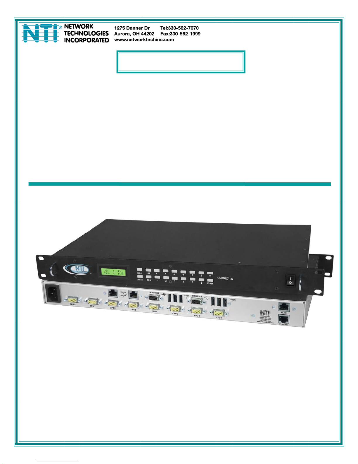
NTI UNIMUX MULTI-USER KVM SWITCH
INTRODUCTION
The NTI UNIMUX-nXm-UHD is a High Density USB VGA KVM Matrix Switch, (n= number of users, m= number of CPUs). It
allows up to four users, each with USB user devices and monitor, to communicate directly with any WINDOWS, MAC and/or SUN
USB CPU (up to 32) connected to the switch. These CPUs can be file servers, web servers, etc. The auto-boot circuitry in the
UNIMUX USB KVM switch allows all CPUs to boot simultaneously without keyboard and/or mouse error.
Definitions
• CPU
• User Device
• System
• OSD
Enclosure that contains the operating system and processor
Keyboard , Mouse or Touchscreen,Smart Card, Whiteboard
One or more CPUs connected to one or more switches controlled by one or more user devices
On Screen Display
Compatibility
Supported USB CPUs:
• Windows USB CPUs
• SUN (including all SUN Blades and SUN Rays) USB CPUs (see page 53 re: SUN Ray support
• MAC USB CPUs
Supported User Devices and Monitors:
• VGA, XGA, SVGA, and most DVI monitors (when used with NTI DVIF-15HDM adapter)
• Most USB mice and keyboards including wireless mice and keyboards
Supported non-HID (Human Interface Device) devices (UNIMUX-nXm-UHDU models only)
• SMART Whiteboard with USB support
• Most USB Touch Screen monitors
Tested:
o NEC E222W
o IED IWS-240T-G3
o COMPAQ L2105
o Magic Touch
o Orbit 60380-2
• Most USB Smart Cards
• Motorola Symbol LS340 8 Bar Cod e Scanner
Supported remote CPU access device:
For remote access to CPU connected to the switch, via WAN or PSTN, use INTERMUX-KVMUIP (sold separately)-see
page 14.
)
1

NTI UNIMUX MULTI-USER KVM SWITCH
ORDERING INFORMATION
The UNIMUX-nXm-UHD switch is built to a specific size ranging from 2 or 4 users and 8 to 32 CPUs. The switch is built at the
factory based on the specified size ordered. The switch has USB inputs and outputs that support all platforms and are configured
with interface cables (see cable section-page 61). The “n” in the part number UNIMUX-nXm--U represents the number of users.
Select either 2 or 4 user switches. The “m” in the part number represents the number of CPUs. The switch is available with either
8, 16 or 32 sets of CPU ports. It is not necessary to connect a user or CPU to each port (I.e. a UNIMUX-2x16-UHD switch has the
capability of supporting 16 CPUs, but can have only 10 CPUs connected and 6 empty ports.
UNIMUX-nXm-UHD
Replace the “n” with either 2 or 4
Replace the “m” with either 8, 16, or 32
The following list represents the available sizes that can be ordered:
UNIMUX-2X8-UHD UNIMUX-4X8-UHD
UNIMUX-2X16-UHD UNIMUX-4X16-UHD
UNIMUX-2X32-UHD UNIMUX-4X32-UHD
Options:
Extra USB device port for connection of USB cable from touch screen monitor, smart card, or whiteboard- add a “U” to the part
number (i.e. UNIMUX-nXm-UHDU)
Add an RJ45 port for CAT5 extension to remotely locate the user up to 300 feet away using an ST-C5USBV-300-R (Sold
separately)- add a “C5” to the part number (i.e. UNIMUX-nXm-UHDC5 or UNIMUX-nXm-UHDUC5)
Remove VGA video support and switch only the keyboard and mouse- add a “NV” to the part number
(i.e. UNIMUX-2X8-UHD-NV)
2
NTI UNIMUX MULTI-USER KVM SWITCH
MATERIALS
Materials Supplied:
• NTI UNIMUX-nXm-UHD Multi-user USB KVM Switch
• IEC Power cord- country specific
• 4-#10-32 x 3/4" pan head screws and #10-32 cage nuts (server cabinet mounting hardware)
• CD with pdf file of this manual and RS232 control software
• DB9 Female-to-RJ45 Female adapter
• 5 foot RJ45-to-RJ45 CAT5 patch cable
Materials Not Supplied, but REQUIRED
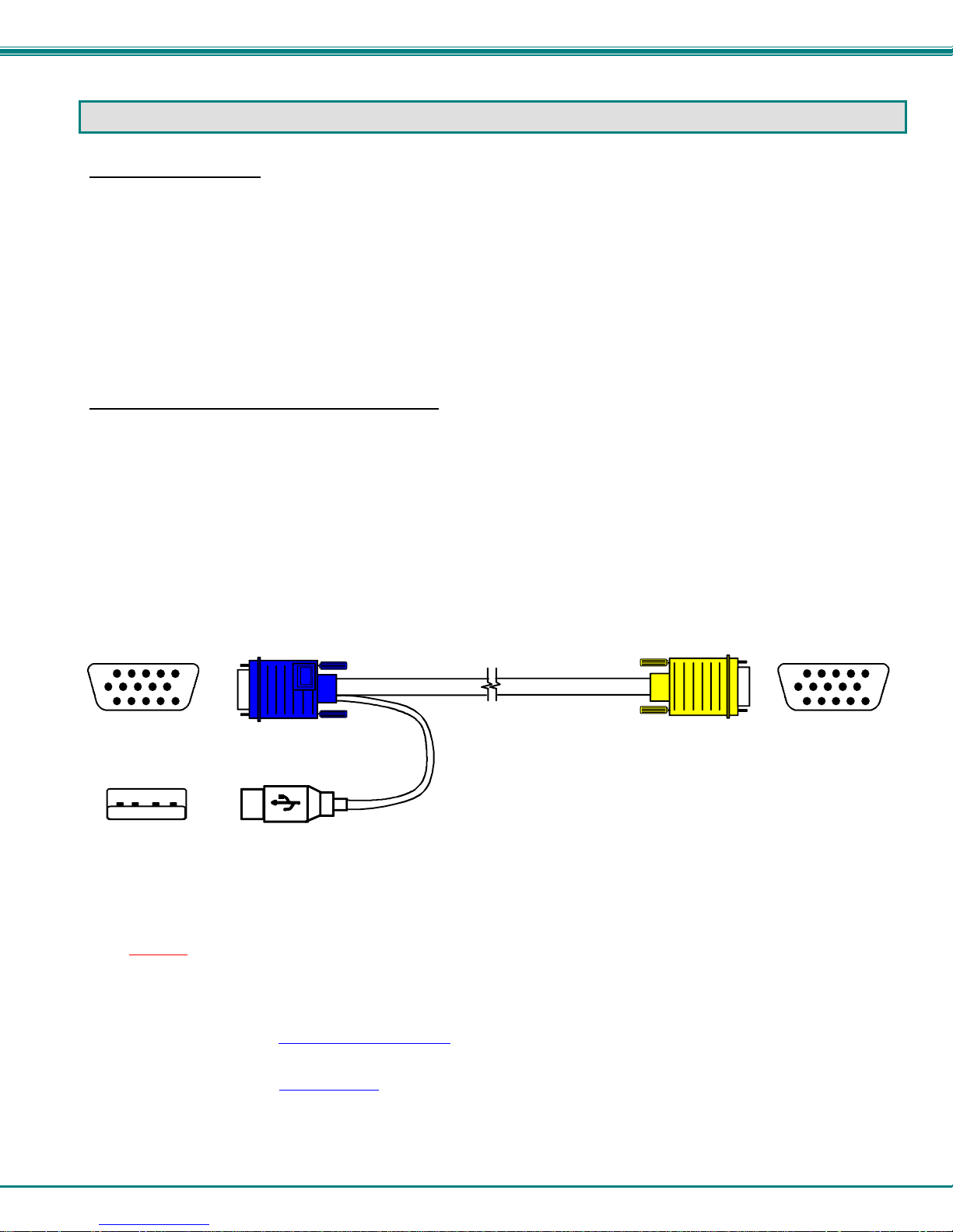
• HDUSBVEXT-xx-MM cable for each CPU being connected to the switch (models with video support)
• HDUSB-3-MM / HDUSB-6-MM cables (3 foot or 6 foot) for each CPU being connected to the switch (for models without video
support (“-NV”))
Where:
xx is the length of the cable in feet (3,6,10, or 15 feet available)
MM indicates male-to-male connector
15HD-Male
USB Type A
Male
Required for models with Remote User support via CAT5:
HD15 Male
Video
USBType A Male
HDUSBVEXT-xx-MM
(3,6,10 and 15 foot ca bles available)
HD15 Male
High Density
15HD-Male
• CAT5/5e/6 unshielded twisted-pair cable(s) terminated with RJ45 connectors wired straight thru- pin 1 to pin 1, etc. (see
page 61 for proper EIA/TIA 568 B wiring method)
Note: Shielded
meet CE emission requirements.
Cables can be purchased from Network Technologies Inc by calling 800-RGB-TECH (800-742-8324) or 330-562-7070
or by visiting our website at www.networktechinc.com
See page 61 for some of the available cables
CAT 5,5e, or 6 cable must be used to connect between the switch and Remote extender unit in order to
.
.
3
NTI UNIMUX MULTI-USER KVM SWITCH
U
R
NTI
Network Tec hnol ogi es I nc
Front View of UNIMUX-4X8-UHD
TM
UNIMUX
USR
Esc
678
Menu
12
CPU 4 5
3
90
*
Enter
HD
1
2
AC INPUT
100-240VAC
10W
4
3
Rear View of UNIMUX-4X8-UHD
6
USER 3USER 4
7
USER 1USER 2
8
RS232
R
NTI
1275 Danner Dr
Aurora, OH 44202
Tel:330-562-7070
Fax:330-562-1999
CPU 1 CPU 2 CPU 5 CPU 6 CP U 7 CPU 8 CPU 3 CPU 4
www.networktechinc.com
ETHERNET
9
5
USER 1
AS SEEN ON
NIMUX-4X8-UHDU
10
Rear View of UNIMUX-4X8-UHDUC5
6
7
8
AC INPU T
100-240VAC
15W
USER 3
USER 4
4
3
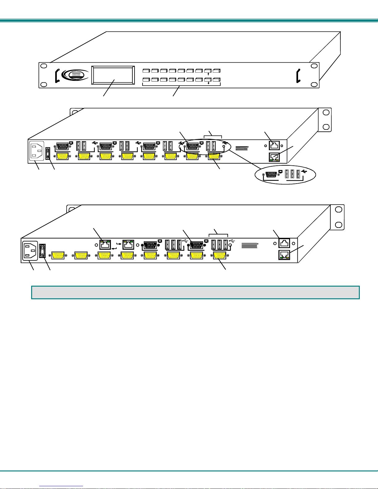
FEATURES AND FUNCTIONS
1. LCD- for visual indication of connection between the user and a specific CPU.
2. Keypad- buttons for user control over switch functions
3. IEC Power Connector- for attachment of power cord
4. Power switch- for turning the power to the UNIMUX On/Off
5. CPU x- 15HD yellow female high-density connectors- for connection of CPU cables for video and device support
6. MONITOR x- 15HD female connectors- for connection of user monitors
7. USB User Device x- USB Type A female connectors (2) - for connection of user device cables;
Another USB Type A female connector may be present (total of 3 per user) for USB cable from
non-HID devices supported (UNIMUX-nXm-UHDU models only)
8. RS232- for attaching RS232 interface cable from a CPU to control the functions of one or more switches
9. ETHERNET- RJ45 female- for connection to an Ethernet for remote multi-user control via TCP Port 2005
10. CAT5- RJ45 female- for connecting a CAT5 cable from an ST-C5USBV-R-300 extender for extended user control
(models with CAT5 support only)
USER 2
RS232
USER 1
R
NTI
1275 Danner Dr
Aurora, OH 4 4202
Tel:330-562-7070
Fax:33 0-562-1 999
CPU 1 CPU 2 CPU 5 CPU 6 CPU 7 CP U 8 CPU 3 CPU 4
www.networktech in c.co m
ETHERNET
9
5
4

NTI UNIMUX MULTI-USER KVM SWITCH
Additional Features
• A single CPU can be used by one or shared by several users.
• Any USB type user device can control any USB CPU (Windows, MAC, and SUN platforms).
• Power cycle circuit control allows the UNIMUX switch to be powered OFF, then ON, at any time without affecting the attached
CPUs. (This assumes that the CPU supports hot plugging.)
• Security features can be enabled on a user port by user port basis.
• A microprocessor is dedicated to each CPU, preventing connected CPUs from locking up and allowing all CPUs to bo ot at
the same time.
• Any user device cable can be hot-plugged.
• The front panel LCD indicates the CPU to which each user is connected.
• 10 configurations can be saved in memory by the user for instant setup recall.
• No dip-switches or jumpers necessary to configure.
• Video formats up to 2048X1536 can be displayed from all platforms.
• Users can control the switch using the On Screen Display
• RS232 control allows control of the switch with one CPU serial port. (Windows-based software is provided.)
• Matrix Switcher's Control Program
interface. (Windows only.)
provides easy and powerful graphical control of matrix switches through the RS232
(OSD)
5
NTI UNIMUX MULTI-USER KVM SWITCH
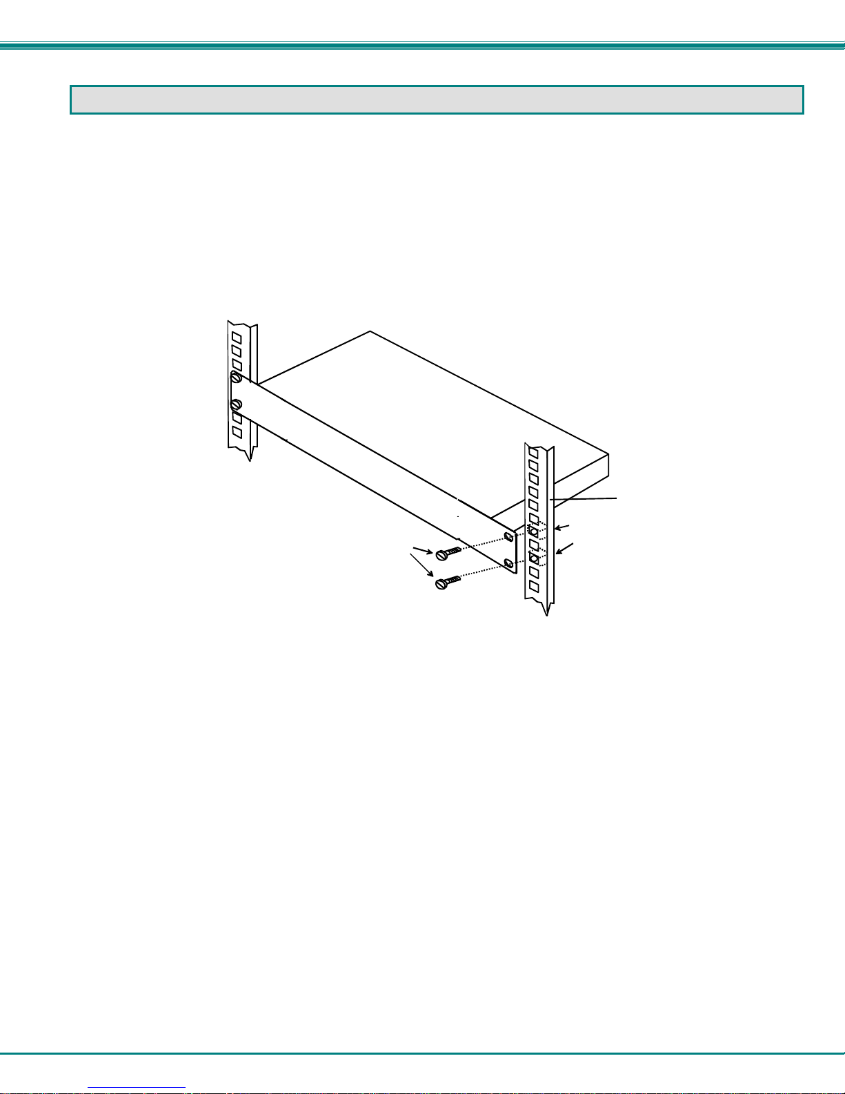
RACK MOUNTING INSTRUCTIONS
This NTI switch was designed to be directly mounted in a rack and includes a mounting flange to make attachment easy.
Install 4 cage nuts (supplied) to the rack in locations that line up with the holes (or slots) in the mounting flange on the NTI switch.
Then secure the NTI switch to the rack using four #10-32 x3/4” screws (supplied). Each screw should be of sufficient length to
go completely through the NTI mounting flange, rack frame and fully engage all threads in the captive nut. Be sure to tighten all
mounting screws securely.
Do not block power supply vents in the NTI switch chassis (if provided). Be sure to enable adequate airflow in front of and
behind the NTI switch.
Attach all cables securely to the switch and where necessary supply adequate means of strain relief for cables.
Cage Nuts
#10-32x3/4"
(supplied)
Rack Screws
(supplied)
Figure 1- Mount Switch in a Rack
Rack
6
NTI UNIMUX MULTI-USER KVM SWITCH
INSTALLATION
It is not necessary to turn OFF power to CPUs or monitors during this installation unless RS232 is going to be connected. All
cables, except for the RS232 cables, may be hot plugged.
If using RS232 Control see RS232 section
RS232 cables to the CPU. Refer to the owner’s manual for the CPU being connected for precautions, if any.
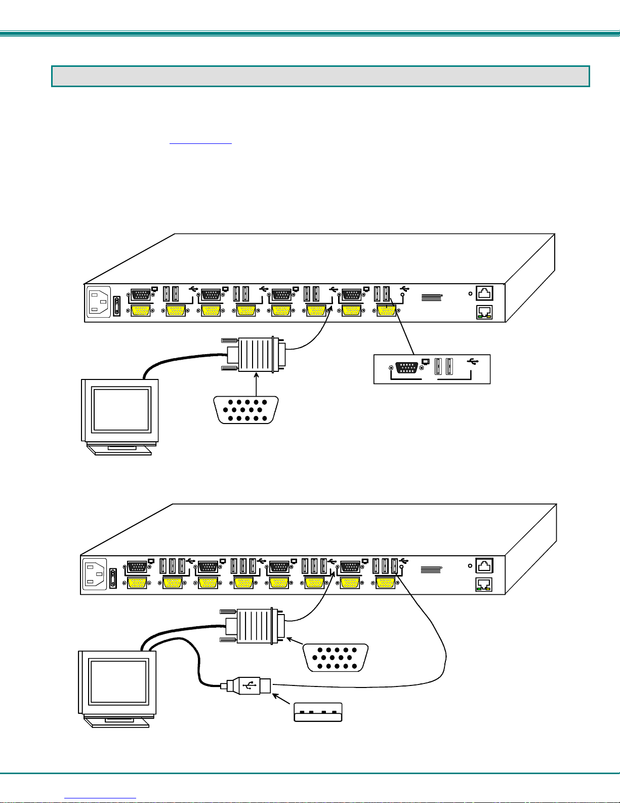
1. Connect the 15HD male cable end from each user monitor to the female black 15HD ports marked “MONITOR x” on the rear of
the UNIMUX switch (see Figure 2 ). If a touch screen monitor is being connected (models with touch screen support only),
connect the USB cable from the monitor to any one of the USB type A connectors in the same user device port group (see
Figure 3 ).
AC INPUT
100-240VAC
10W
Existing Cable
VGA
Monitor
on page 38 for more information. Observe normal precautions when connecting the
Rear View of UNIMUX-4X8-UHD
RS232
R
NTI
USER 3USER 4
Mating Face of
15HD Male
USER 1USER 2
CPU 3 CPU 4
CPU 1 CPU 2 CP U 5 CPU 6 CPU 7 CPU 8
1275 Danner Dr
Aurora, O H 44202
Tel:330-562- 7070
Fax:330-562- 1999
www.ne twor ktechi nc.com
USER 1
ETHERNET
User Device Ports
(For User 1)
Figure 2- In stall user monitor(s)
Rear View of UNIMUX-4X8-UHDU
AC INPU T
100-240VAC
10W
USER 3USER 4
CPU 3 CPU 4
USER 1USER 2
CPU 1 CPU 2 CPU 5 CPU 6 CPU 7 CPU 8
Existing Cable
VGA
Touch Screen
Monitor
Mating Face of
15HD Male
USB Type A Male
Figure 3- Install user touch screen monitor
NTI
1275 Danner Dr
Aurora, OH 44202
Tel:330-562-7070
Fax:330-562-1999
www.ne two rktechi nc.c om
RS232
R
ETHERNET
7
NTI UNIMUX MULTI-USER KVM SWITCH
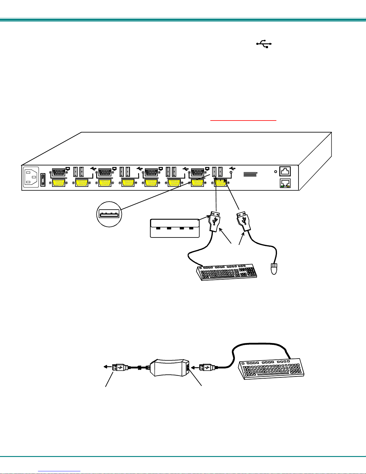
2. Connect the user devices to the USB type A female ports labeled with the USB symbol ( ) on the rear of the UNIMUX
switch (see Figure 4 ). Ensure that the monitors and related user devices are connected to ports from the same device port
group.
Note: If there are three (3) USB type A female ports present (models with touch screen support only), then the third USB
port is available for connection of a USB cable from a touch screen type monitor. The USB ports are not device specific,
so the mouse, keyboard, and USB cable from a touch screen type monitor (or other suppported device) can be
connected to any of the available USB ports present.
Note: If device cables are not long enough to reach the UNIMUX switch, they can be extended either 5 or 10 meters
using either 1 or 2 NTI USB2-AA-5M Active USB 5 Meter Extensions (see Figure 5)- purchased se parately. Using USBC5-LC you can extend device cables up to 150 feet. Contact your NTI salesperson for more details by calling (800) 7428324 (800-RGB-TECH) or (330) 562-7070 or visit our website at http://www.networktechinc.com
Rear View of UNIMUX-4X8-UHD
AC INPUT
100-240VAC
10W
USER 3USER 4
CPU 3 CP U 4
USER 1USER 2
CPU 1 CPU 2 CPU 5 CPU 6 CPU 7 CPU 8
NTI
1275 Danner Dr
Aurora, OH 44202
Tel:330-562-7070
Fax:330-562-1999
www.networktechinc.com
R
USB Type A Female
USB Type A Male
USB Type A
Male Connectors
USB Keyboard
.
RS232
ETHERNET
USB
Mouse
Figure 4- Install user devices (mouse and keyboard)
TO UNIMUX
SWITCH
USB TYPE A
MALE CONNECTO R
Figure 5- Use USB2-AA-5M to extend a device, or a computer
USB2-AA-5M
FEMALE CONNECTOR
USB TYPE A
8
USB KEYBOARD
NTI UNIMUX MULTI-USER KVM SWITCH
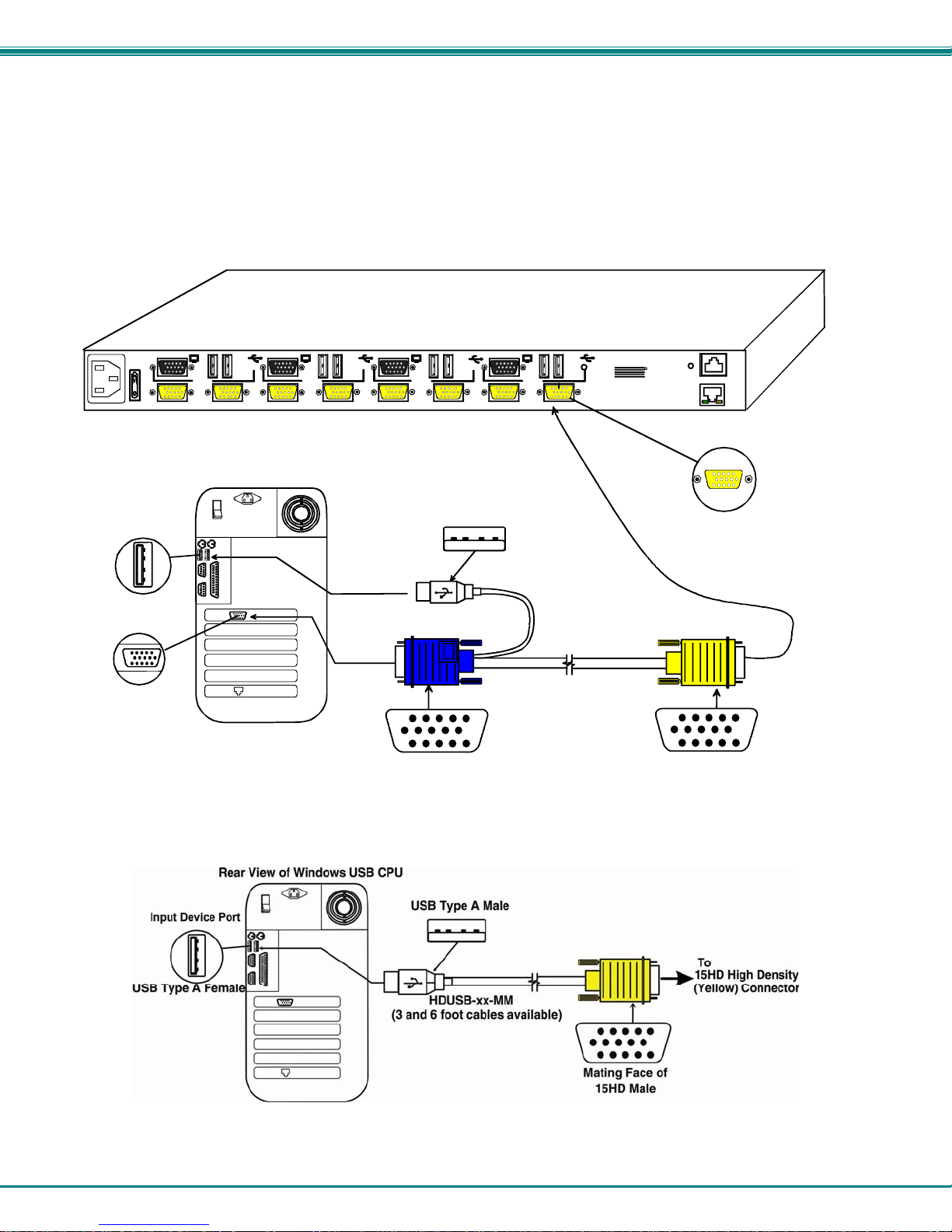
3. For each CPU:
• Connect a USB type A cable end of a HDUSBVEXT-xx-MM cable to a USB type A female user device port on a CPU.
(For models without video support, this would be a HDUSB-xx-MM cable. )
• Connect the 15HD blue male cable end of a HDUSBVEXT-xx-MM cable to the video port of the same CPU.
• Connect the 15HD yellow male cable end of the HDUSB(VEXT)-xx-MM cable to a yellow “CPU x” port on the UNIMUX
switch. (See Figure 6)
AC INP UT
100-240VAC
10W
Input Device Port
USB Type A Female
Video Port
15HD Female
Video Connector
Rear View of Windows USB CPU
Rear View of UNIMUX-4X8-UHD
NTI
1275 Danner Dr
Aurora, OH 44202
Tel:330-562-7070
Fax:330-562-1999
www. netwo rkte chinc .com
CPU 3 CP U 4
USB Type A Male
(3,6,10 and 15 foot cables available)
Mating Face of
15HD Male
USER 1USER 2USER 3USER 4
CPU 1 CPU 2 CPU 5 CP U 6 CPU 7 CPU 8
HDUSBVEXT-xx-MM
RS232
R
ETHERNET
15HD High Density
(Yellow) Connector
Mating Face of
15HD Male
Figure 6- Connect each CPU using a HDUSBVEXT-xx-MM cable
Figure 7- Connect each CPU using a HDUSB-xx-MM cable
9

NTI UNIMUX MULTI-USER KVM SWITCH
4. Power-up
• Plug the UNIMUX switch into an AC power outlet.
• Turn ON power to the UNIMUX switch, the LCD should illuminate.
• Turn ON power to any or all CPUs connected to the UNIMUX switch (if they aren't ON already).
Note: The order in which the CPUs and switch are powered up does not matter. A power strip can be used.
10
NTI UNIMUX MULTI-USER KVM SWITCH
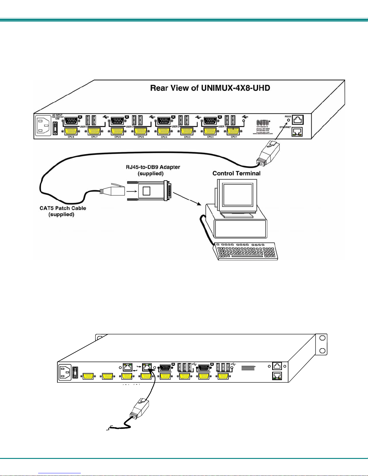
RS232 Connection
If RS232 control will be used, connect one end of the CAT5 patch cable (supplied) to the port labeled “RS232” o n the rear of the
UNIMUX. Plug the other end of the CAT5 cable into the RJ45-to-DB9 adapter supplied and connect the adapter to the RS232
port on the control terminal. Follow the instruction under “RS232 Control” on page 38 for configuration and use of the RS232
control feature.
Figure 8- Connect cable for RS232 control
CAT5 Connection
If the CAT5 extender option is present, a CAT5 cable up to 300 feet long can be connected between the “USERx” ports that
are RJ45 female connectors and an ST-C5USBV-R-300 extender Remote Unit (sold separately). We will use “USER 3” for
this example.
AC INPUT
100-240VAC
15W
USER 3 Connected vi a
CAT5 Cable to
ST-C5USBV-R-300
Remote Unit
Figure 9- Connect CAT5 cable for remote user
Rear View of UNIMUX-4X8-UHDUC5
USER 3
USER 4
USER 2
USER 1
CPU 1 CPU 2 CPU 5 CPU 6 CP U 7 CP U 8 CPU 3 CPU 4
NTI
1275 Danner Dr
Aurora, OH 44202
Tel:330-562-7070
Fax:33 0-562-1 999
www.networ k techinc.co m
RS232
R
ETHERNET
11
NTI UNIMUX MULTI-USER KVM SWITCH
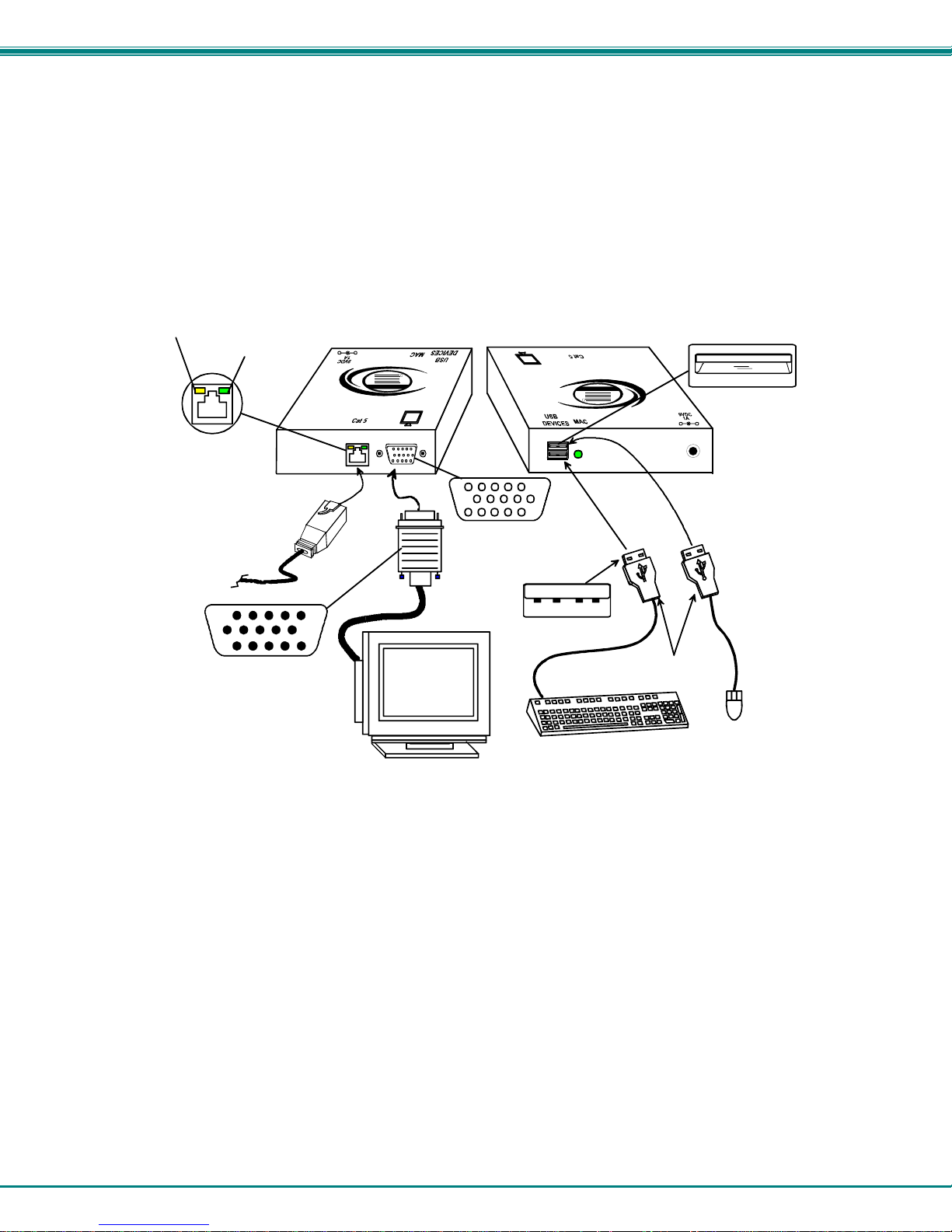
1. Position the ST-C5USBV-R-300 such that the CAT5 cable, the monitor cable, the keyboard and mouse, and the AC adapter
power connector can each reach the ST-C5USBV-R-300 comfortably.
2. Connect the monitor cable to the 15HD female VIDEO port on the ST-C5USBV-R-300. (See Figure 10)
3. Connect the devices to the ST-C5USBV-R-300.
a. Connect the USB keyboard cable to one of the USB Type A female ports labeled "USB DEVICES" on the back
of the ST-C5USBV-R-300. (Either one will work.)
b. Connect the USB mouse cable to the remaining USB Type A female port on the back of the ST-C5USBV-R-
300.
Yellow Communication LED
Green Power LED
ST-C5USBV-R-300 Remote Unit
(Front View)
-
+
R
NTI
Network Technologies Inc
USB
XTENDEX
(Rear View )
USB
R
USB Type A Female
XTENDEX
Network Technologies Inc
NTI
+
-
CAT5 Cable to
"USER 3" on
UNIMUX-4X8-UHDUC5
15HD male
Video Connector
Multi-Scan
15HD Female
Video Connecto r
VGA
Monitor
USB Type A male
male connectors
USB Keyboard
USB Type A
USB
Mouse
Figure 10- Connect monitor and devices to ST-C5USBV-R-300
4. Plug the power cord from the monitor into a power outlet.
5. Connect the AC adapter power connector to the 9VDC port on the Remote Unit and plug it into a power outlet. The “Power”
LED (Green) on the CAT5 connector of the Remote Unit should illuminate, indicating that a proper power connection has
been made.
6. Turn ON the monitor. The monitor will display an image coming from the CPU that User 3 is connected to via the UNIMUX
switch. The yellow communication LED on the Remote Unit (see Figure 10) should blink indicating there is proper
communication with the UNIMUX.
12
NTI UNIMUX MULTI-USER KVM SWITCH
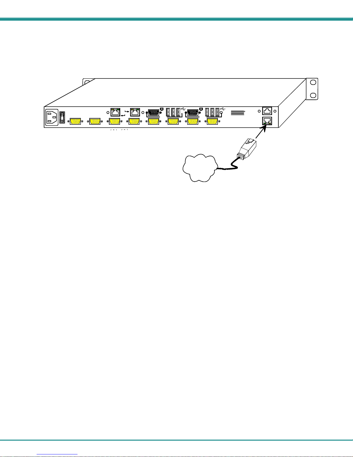
Ethernet Connection
If the Telnet Interface (page 44) will be used, an Ethernet connection to the Local Area Network (LAN) must be made using CAT5
cable with RJ45 connectors attached. Wiring between connectors should be straight through (pin 1 to pin 1, pin 2 to pin 2, etc..)
Connect a CAT5 cable between the connector labeled "ETHERNET" and the LAN (see Figure 11).
AC INPUT
100-240VAC
15W
Rear View of UNIMUX-4X8-UHDUC5
USER 3
USER 4
USER 2
USER 1
CPU 1 CPU 2 CPU 5 CPU 6 CPU 7 CPU 8 CPU 3 CPU 4
RJ45-male
connector
LAN
NTI
1275 Danner Dr
Aurora, OH 44202
Tel:330-562-7070
Fax:330-562-1999
www.netwo rk techinc. co m
RS232
R
ETHERNET
Figure 11- Connect LAN to Ethernet port
13
NTI UNIMUX MULTI-USER KVM SWITCH
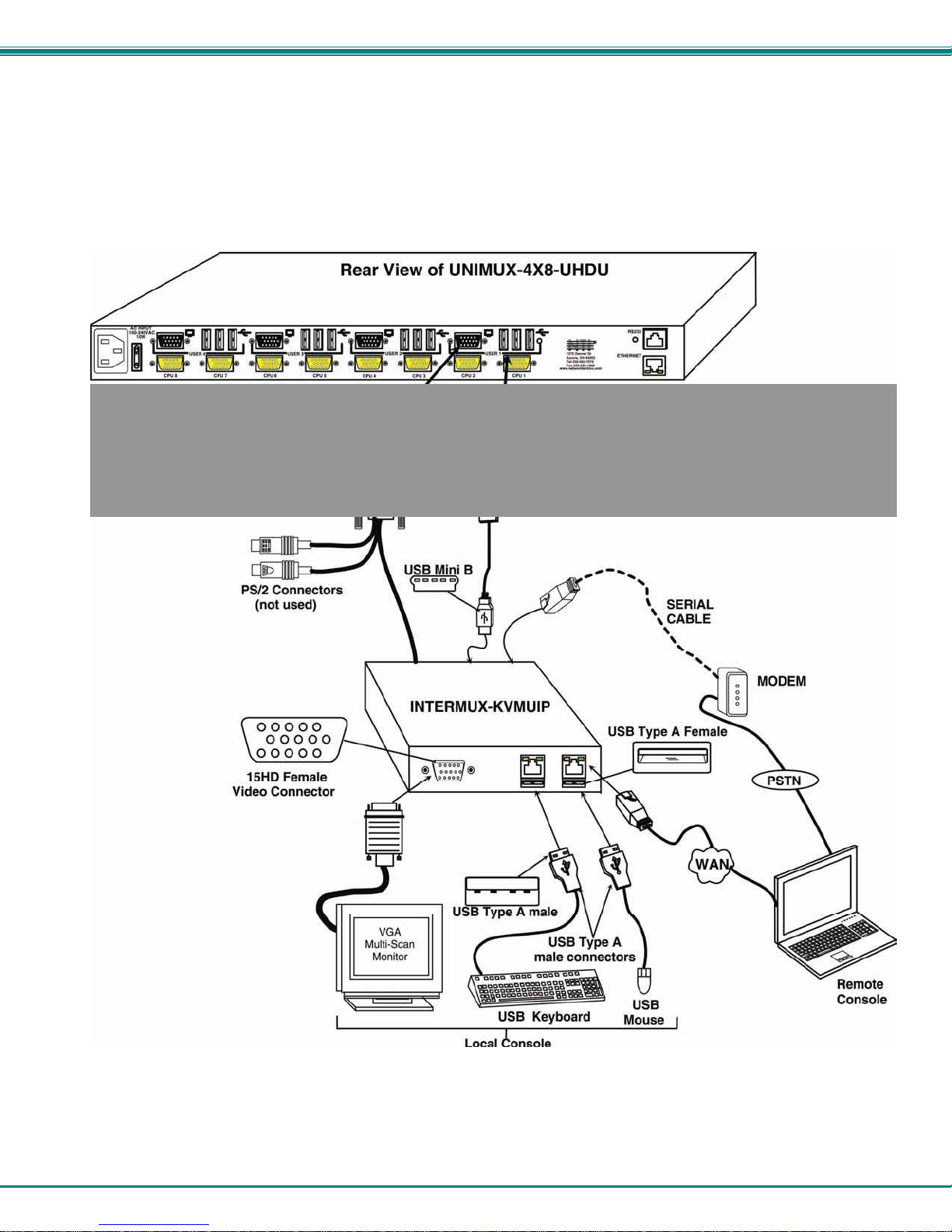
Remote CPU Access
In order to have access to a User port from anywhere either over a network or through a serial connection via a PSTN, an
INTERMUX-KVMUIP can be installed to one of the USERx ports. This will provide user control over any of the CPUs connected
to the UNIMUX switch.
Install the INTERMUX-KVMUIP as illustrated below. See manual that accompanies the INTERMUX-KVMUIP for more details.
Figure 12- Install INTERMUX-KVMUIP
14
NTI UNIMUX MULTI-USER KVM SWITCH
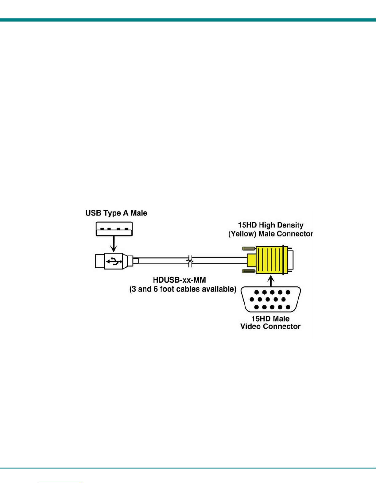
No-Video Models
Some models of UNIMUX Hi Density USB KVM Switch have been specially designed without support for video. As
such, the OSD menu control described in this manual cannot be used. To control the No-Video version of this
product, use the following control methods described in the manual:
• front panel control using touch-switches and LEDs (see page 17)
• RS232 control (see page 38)
• Telnet Interface- via command line interface (see page 44)
Note: Ethernet configuration cannot be changed using the OSD menu in the absence of video support.
Instead, to change network settings, use the NTI Discovery Tool provided on the CD (page 49). (Default
configuration settings can be found on page 31.)
Cables are available from NTI having only the 15HD high density connector at one end and USB Type A male
connector at the other end (HDUSB-x-MM where x = 3 or 6 feet).
Figure 13- Cable for USB-only support
15
 Loading...