

UNIMUX Series
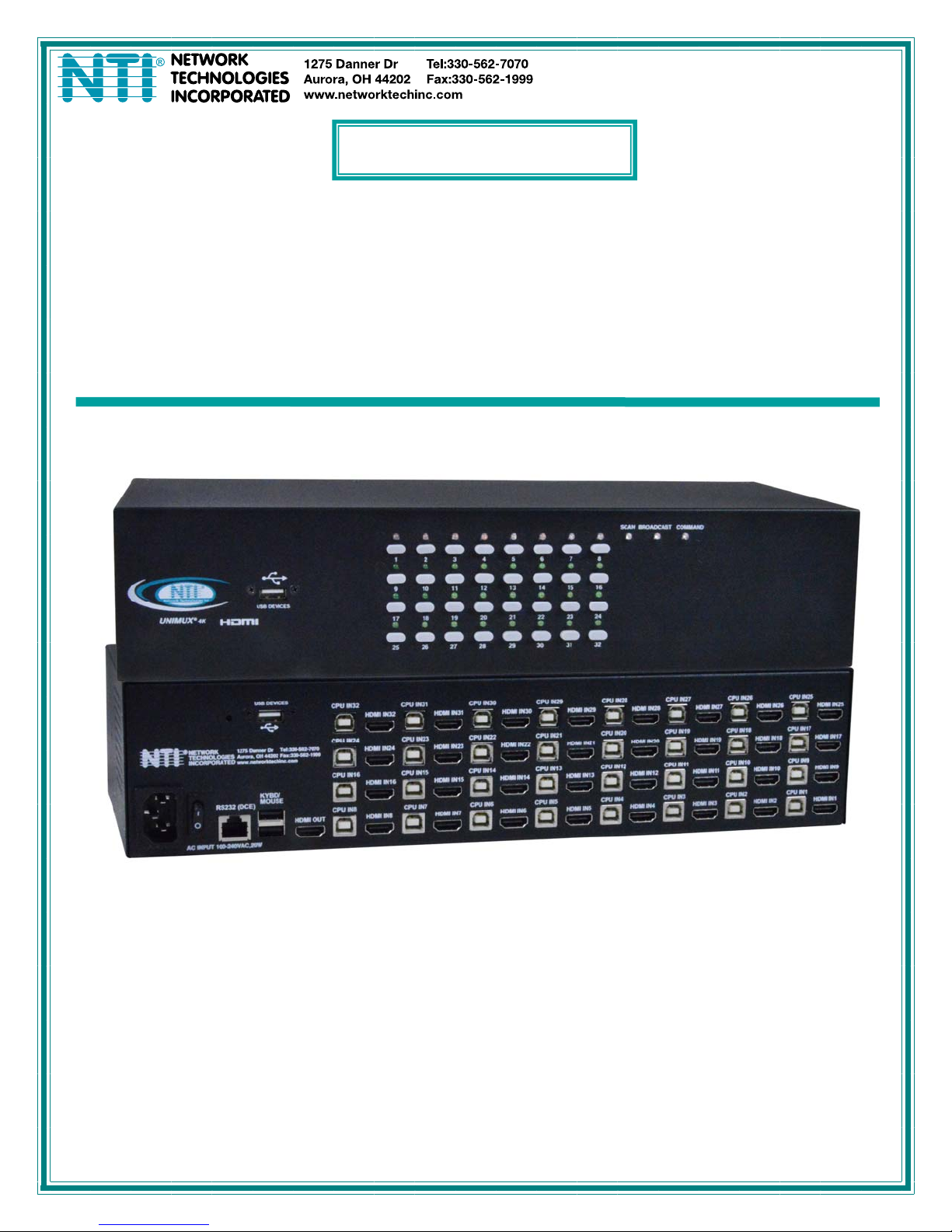
UNIMUX-HD4K-x
4K Video USB KVM Switch
Installation and Operation Manual
UNIMUX-HD4K-32 (Front and Rear View)
MAN305 Rev Date 6/1/2018

TRADEMARK
UNIMUX is a trademark of Network Technologies Inc in the U.S. and other countries
COPYRIGHT
Copyright © 2000, 2018 by Network Technologies Inc. All rights reserved. No part of this publication may be reproduced, stored
in a retrieval system, or transmitted, in any form or by any means, electronic, mechanical, photocopying, recording, or otherwise,
without the prior written consent of Network Technologies Inc, 1275 Danner Drive, Aurora, Ohio 44202.
CHANGES
The material in this guide is for information only and is subject to change without notice. Network Technologies Inc reserves the
right to make changes in the product design without reservation and without notification to its users.
.
Typographic Conventions
The table below offers examples of text format and its meaning when that format is used in place of the standard font (Helvetica)
used throughout this manual.
Typeface meaning Font Configuration Example
On-screen computer output Courier New-(not bold)
What you type on the computer Courier New-bold
C:>
C:>edit text.bat
i

TABLE OF CONTENTS
INTRODUCTION.............................................................................................................................................................1
Features....................................................................................................................................................................1
MATERIALS....................................................................................................................................................................1
FEATURES AND FUNCTIONS.......................................................................................................................................2
RACKMOUNTING INSTRUCTIONS...............................................................................................................................3
To Mount to a Rack .....................................................................................................................................................3
INSTALLATION...............................................................................................................................................................4
RS232 Connection.......................................................................................................................................................6
Power-Up Sequence....................................................................................................................................................7
Limitations....................................................................................................................................................................7
USING THE UNIMUX SWITCH ......................................................................................................................................8
Front Panel Control......................................................................................................................................................8
Keyboard Control.........................................................................................................................................................8
USER ACCESS FUNCTIONS.........................................................................................................................................9
Command Mode..........................................................................................................................................................9
Navigation.................................................................................................................................................................9
Settings Menu.........................................................................................................................................................10
Broadcast Mode......................................................................................................................................................11
Scan Mode..............................................................................................................................................................12
Normal Mode ..........................................................................................................................................................13
Administrator Settings.............................................................................................................................................14
Port Name List........................................................................................................................................................15
RS232 CONTROL.........................................................................................................................................................16
RS232 Connections and Configuration.....................................................................................................................16
Remote Connection................................................................................................................................................16
Baud Rate...............................................................................................................................................................16
Command Protocol.................................................................................................................................................16
NTI Switch Control Program For Windows 9X, NT, 2000, XP, Vista,7, 8 and 10 ....................................................17
SerTest- RS232 Interface Test Program...................................................................................................................18
Main Options...........................................................................................................................................................18
KEYBOARD FEATURES..............................................................................................................................................22
Keyboard-To-Computer Translation..........................................................................................................................22
Translation Capabilities ..........................................................................................................................................22
TROUBLESHOOTING..................................................................................................................................................23
INDEX............................................................................................................................................................................23
WARRANTY INFORMATION........................................................................................................................................23
TABLE OF FIGURES
Figure 1- Secure rackmount ears to switch.....................................................................................................................3
Figure 2- Secure switch to a rack....................................................................................................................................3
Figure 3- Connect a VGA multi-scan monitor .................................................................................................................4
Figure 4- Connect the device(s)......................................................................................................................................4
Figure 5- Connect the AC line cord.................................................................................................................................5
Figure 6- Connect each CPU..........................................................................................................................................5
Figure 7- Connect Terminal for RS232 Control...............................................................................................................6
Figure 8- Compatible device combinations.....................................................................................................................7
Figure 9- Port List (Main Menu) ......................................................................................................................................9
Figure 10- Help Menu....................................................................................................................................................10
Figure 11- Settings Menu..............................................................................................................................................10
Figure 12- Stop USB Device Reminder warning...........................................................................................................11
Figure 13- Settings Menu..............................................................................................................................................11
Figure 14- Broadcast List..............................................................................................................................................12
Figure 15- Settings Menu..............................................................................................................................................12
ii

Figure 16- Scan List......................................................................................................................................................13
Figure 17- Administrator Settings..................................................................................................................................14
Figure 18- Port Name List.............................................................................................................................................15
Figure 19- RS232 Communication Illustrated...............................................................................................................16
Figure 20- Keyboard Layouts........................................................................................................................................22
iii

NTI UNIMUX SERIES 4K VIDEO USB KVM SWITCH
INTRODUCTION
The UNIMUX-HD4K-x 4K Video USB KVM switches allow a single user to control of 4, 8, 16, 24, or 32 computers with an HDMI
monitor and USB keyboard and mouse. These switches feature an on-screen display (OSD) and a fully transparent USB switch.
(This means that when a USB device is connected to a transparent USB port, it is the same as if the device was being plugged
directly into the computer's USB port.) Connections use standard HDMI and USB cables.
HDMI 1.4 resolutions up to 4k @ 30Hz are supported.
The transparent switch is capable of supporting any two low-, full-, or high-speed USB 2.0 devices, including but not limited to
touchscreens, card readers, printers, scanners, and thumb drives.
Note: Devices vulnerable to data corruption upon surprise removal, such as thumb drives, have to be stopped by the us er before
switching hosts (i.e., by Windows safely remove hardware or Mac eject device). A warning to this effect, requiring user
confirmation, is displayed on the OSD when attempting to switch hosts or enter scan mode. This warning appears by default,
though it is possible to disable it in the switch settings.
Internal microprocessor circuitry allows all USB CPUs to be booted simultaneously without keyboard error. Port selection is
accomplished by front panel push buttons or commands typed on the keyboard. Port lights and status LEDs continuously update
on the front panel. Video formats up to 2560x1440 can be displayed from all platforms.
Features
HDMI 1.4, DVI compatible (with optional HDMI to DVI cable).
Resolutions to 2560x1440 (computer), 3840x2160 (UHD), and 4096x2160 (4K) @ 30Hz / 4:4:4 RGB (resolutions limited
to 1920x1200 when mounted in a RACKMUX drawer).
HDCP 1.4.
Supports low- or full-speed USB keyboard and mouse.
On screen display for controlling switch and modifying settings, uses attached mouse an d keyboard.
Synchronized 2-port transparent USB 2.0 switch.
Passes embedded audio.
MATERIALS
Materials supplied with this kit:
NTI UNIMUX-HD4K-x (4,8,16,24 or 32 ports) USB 4K Video KVM Switch
Line cord, country specific
Rack mount kit
1- DB9 Female-to-RJ45 Female adapter
1- 5 foot RJ45-to-RJ45 CAT5 patch cable
4- Rubber feet
Materials Not supplied but REQUIRED:
HD-xx-MM cable for each 4K monitor being connected to the switch and for each PC being connected- available in 3, 6,10,
15,20,30,50,75 and 100 foot lengths
where:
xx is the length of the cable in feet
MM indicates male-to-male connector
USB 2.0 A-B cable for each USB device being connected to the switch. Many are available from NTI in 0.5 meter and 3,6,10
and 15 foot lengths. Go to https://www.vpi.us/c/2-0-usb-cables-159
Cables can be purchased from Network Technologies Inc by calling (800) 742-8324 (800-RGB-TECH) in the US and Canada or
(330) 562-7070 (worldwide).
.
1
NTI UNIMUX SERIES 4K VIDEO USB KVM SWITCH
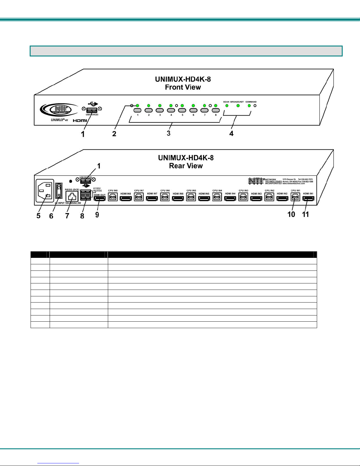
FEATURES AND FUNCTIONS
Item Type Description
USB Type A Female
1
LEDs
2
Switches
3
LEDs
4
IEC Connector
5
Power Switch
6
RJ45 Female
7
USB Type A Female
8
HDMI Female
9
USB Type B Female
10
HDMI Female
11
Transparent USB port for connecting low-, full-, or high-speed USB 2.0 devices
For visual indication of connection between the user and a specific CPU.
Push to manually switch to a specific CPU or change the switch operating mode
For visual indication of switch operating mode
For attachment of country-specific power cord
To control the ON/OFF function of the switch
RS232 (DCE) connection for attachment of RS232 control cable
For connection of user USB device(s)
For connection of user monitor cable
For connection of USB device cable from CPUs
For connection of video cable from CPUs
2
NTI UNIMUX SERIES 4K VIDEO USB KVM SWITCH
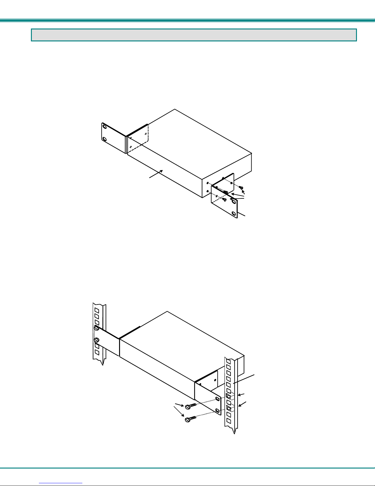
RACKMOUNTING INSTRUCTIONS
This NTI switch was designed to be mounted to a rack or to sit on a desktop. It includes rackmount ears to make attachment to a
rack easy, and rubber feet to be applied to the bottom of the case if it will instead sit on a flat surface. If this will sit on a flat
surface, simply apply the rubber feet to the bottom of the case in each of the 4 corners.
To Mount to a Rack
1. Attach the ears to the switch using the 6-32x3/16" flat Phillips-head screws (6) provided as shown in the illustration below.
The holes in the ears should line up with pre-threaded holes in the sides of the NTI switch. Tighten the screws securely.
Front of Switch
NTI Switch
6-32x3/16"
Flat Head
Screws
(Provided)
Rackmount Ear
Figure 1- Secure rackmount ears to switch
2. Install 4 captive nuts (not provided) to the rack in locations that line up with the holes in the mounting ear on the NTI switch.
3. Secure the NTI switch to the rack using four 3/16" diameter screws (not provided). Each screw should be of sufficient length
to go completely through the NTI mounting ear, rack frame and fully engage all threads in the captive nut. Be sure to
tighten all mounting screws securely.
4. Attach all cables securely to the switch and where necessary supply adequate means of strain relief for cables.
3/16" Diam eter Screw s
(not provided)
NTI Switch
Rack
Captive Nuts
(not provided)
Figure 2- Secure switch to a rack
3
NTI UNIMUX SERIES 4K VIDEO USB KVM SWITCH
INSTALLATION
1. It is not necessary to turn the CPUs or monitors OFF during this installation.
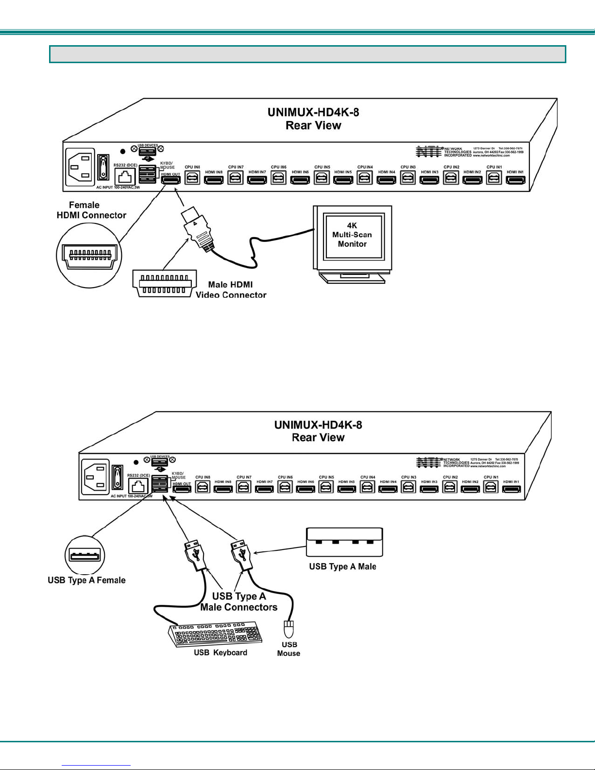
2. Connect the cable from a monitor to the HDMI connector labeled “HDMI OUT” on the UNIMUX (See Fig. 3 below.)
Figure 3- Connect a VGA multi-scan monitor
3. Connect the male USB type A connector on the keyboard cable to either one of the two USB type A female connectors
labeled "KYBD/MOUSE" on the rear panel of the UNIMUX.
4. Connect the male USB type A connector on the mouse cable to the remaining USB type A female connector labeled
"KYBD/MOUSE".
5. Connect the AC line cord to the UNIMUX. (See Fig. 5 below.)
Figure 4- Connect the device(s)
4
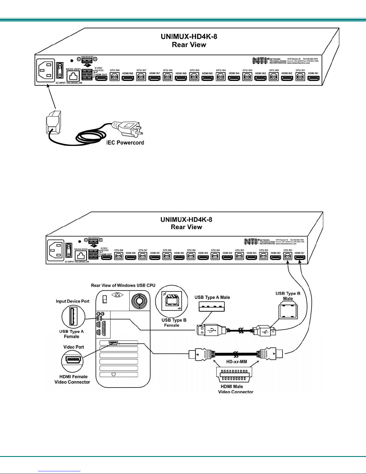
NTI UNIMUX SERIES 4K VIDEO USB KVM SWITCH
Figure 5- Connect the AC line cord
6. Connect each CPU to the USB switch using a HD-xx-MM video and USB Type A-B device cable – REQUIRED
(not supplied). (See Fig. 6 below.)
7. Group the input device and monitor interface cables from each CPU, making sure that cables from the first CPU are
connected to the UNIMUX at connectors "CPU IN1" and "HDMI IN1". Cables from the second CPU should
connect to "CPU IN2" and "HDMI IN2" connectors...etc.
Figure 6- Connect each CPU
5
 Loading...