

NTI TRX, TRX085, TRX150C, TRX120, TRX110C Maintenance Manual
Installation
Start-Up
Maintenance
Parts
Warranty
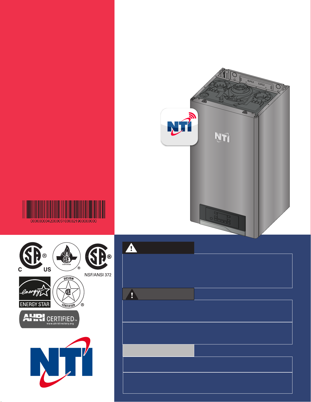
TRX
TRX
Residential Condensing Gas Boiler
Heat Exchanger Bears the ASME “H” Stamp
DANGER
THIS MANUAL MUST ONLY BE USED BY A QUALIFIED INSTALLER /
SERVICE TECHNICIAN. READ ALL INSTRUCTIONS IN THIS MANUAL
BEFORE INSTALLING. PERFORM STEPS IN THE GIVEN ORDER. FAILURE
TO DO SO COULD RESULT IN SUBSTANTIAL PROPERTY DAMAGE, SEVERE
PERSONAL INJURY, OR DEATH.
WARNING
Improper installation, adjustment, alteration, service, or maintenance
could void product warranty and cause property damage, severe
personal injury, or death.
California Proposition 65 Warning: This product contains chemicals
known to the State of California to cause cancer, birth defects, or
other reproductive harm.
NOTICE
The manufacturer reserves the right to make product changes or updates
without notice and will not be held liable for typographical errors in literature.
The surfaces of these products contacted by potable (consumable) water
contain less than 0.25% lead by weight as required by the Safe Drinking Water
Act, Section 1417.
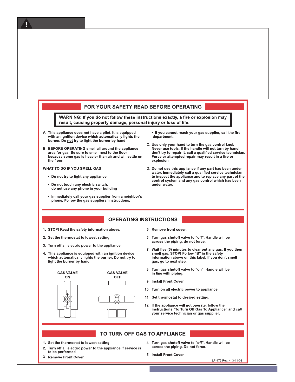
WARNING
WARNING: If the information in these instructions is not followed exactly, a fire or explosion may result causing property damage,
personal injury or death.
• Do not store or use gasoline or other flammable vapors and liquids in the vicinity of this or any other appliance.
WHAT TO DO IF YOU SMELL GAS
• Do not try to light any appliance.
• Do not touch any electrical switch; do not use any phone in your building.
• Immediately call your gas supplier from a neighbor’s phone. Follow the gas supplier’s instructions.
• If you cannot reach your gas supplier, call the fire department.
• Installation and service must be provided by a qualified installer, service agency or the gas supplier.
Improper installation, adjustment, alteration, service, or maintenance can cause injury, property damage, or death.
Refer to this manual. Installation and service must be performed by a qualified installer, service agency, or gas supplier.
2
SPECIAL ATTENTION BOXES
The following defined terms are used throughout this
manual to bring attention to the presence of hazards of
various risk levels or to important product information.
DANGER
DANGER indicates an imminently hazardous situation which,
if not avoided, will result in serious personal injury or death.
WARNING
WARNING indicates a potentially hazardous situation which,
if not avoided, could result in personal injury or death.
CAUTION
CAUTION indicates a potentially hazardous situation which, if
not avoided, may result in moderate or minor personal injury.
CAUTION
CAUTION used without the safety alert symbol indicates a
potentially hazardous situation which, if not avoided, may
result in property damage.
NOTICE
NOTICE is used to address practices not related to personal
injury.
Foreword
This manual is intended to be used in conjunction with other literature
provided with the boiler. This includes all related control information.
It is important that this manual, all other documents included in this
system, and additional publications including the National Fuel Gas
Code - ANSI Z223.1 in the United States and the Natural Gas and Propane
Installation Code - B149.1 in Canada (latest versions), be reviewed in
their entirety before beginning any work.
Installation should be made in accordance with the regulations of
the Authority Having Jurisdiction, local code authorities, and utility
companies which pertain to this type of water heating equipment.
Authority Having Jurisdiction (AHJ) – The AHJ may be a federal, state,
provincial, local government, or individual such as a fire chief, fire
marshal, chief of a fire prevention bureau, labor department or health
department, building official or electrical inspector, or others having
statutory authority. In some circumstances, the property owner or
his/her agent assumes the role, and at government installations, the
commanding officer or departmental official may be the AHJ.
NOTE: The manufacturer reserves the right to modify product technical
specifications and components without prior notice.
For the Installer
This boiler must be installed by qualified and licensed personnel. The
installer should be guided by the instructions furnished with the boiler,
and by local codes and utility company requirements. In the absence
of local codes, preference should be given to the National Fuel Gas
Code - ANSI Z223.1 in the United States and the Natural Gas and Propane
Installation Code - B149.1 in Canada (latest versions).
Installations Must Comply With:
Local, state, provincial, and national codes, laws, regulations, and
ordinances.
In the United States - The latest version of the National Fuel Gas Code,
ANSI Z223.1, from American Gas Association Laboratories, 8501 East
Pleasant Valley Road, Cleveland, OH 44131.
The latest version of the National Electrical Code, NFPA No. 70.
In Canada - The latest versions of the Natural Gas and Propane
Installation Code, CSA B149.1, and the Canadian Electrical Code, C22.1,
from CSA Group, 178 Rexdale Blvd, Toronto, Ontario, Canada M9W 1R3.
NOTE: The gas manifold and controls met safe lighting and other
performance criteria when undergoing tests specified in ANSI Z21.13
- latest edition.
3
WARNING
NOTICE
The hydronic supply and return connections of these products
are for installation in closed loop systems ONLY! Use of this
product in any manner other than described in this manual may
result in premature product failure, substantial property damage,
severe personal injury, or death. Damage or failure of this product
(or the system in which it is installed) due to unauthorized use IS
NOT COVERED BY WARRANTY.
NOTICE
IMPORTANT
In accordance with Section 325 (f) (3) of the Energy Policy and
Conservation Act, NTI has provided this boiler with multiple
features designed to save energy by reducing the boiler water
temperature as heating load decreases.
These features include:
• A modulating combustion system that adjusts firing
rate based on heat demand.
• Adjustment of boiler set point based on inferred heat
load as determined by an outdoor sensor. The outdoor
sensor is supplied with this boiler.
• This boiler does not include a standing pilot.
• This boiler is designed and shipped to assure the highest
efficiency operation possible. Such high efficiency is
achieved by limiting heating circuit water temperature
to 140°F when there is no anticipated heat load, based
upon the outdoor sensor and the Outdoor Reset Curve
(sensor response curve) in the boiler software.
• This feature may be over-ridden as described below in
specific installations:
• The boiler control is equipped with an outdoor sensor
override for use with building management systems
or in cascaded systems (for systems with total input of
300,000 BTU/hr or greater).
See statement below for an important notice on the use of the
override.
ASME CSD-1, Section CW-400 requires the temperature controls of
hot water heating boilers to
a) be accepted by a nationally recognized testing agency to
conform to UL 353,
b) shutoff the fuel supply when the system water reaches a preset
operating temperature,
c) have a high temperature limit control that prevents the
water temperature from exceeding the maximum allowable
temperature by causing safety shutdown and lockout.
The temperature controls of this boiler have been accepted by a
nationally recognized testing agency to conform to UL 353; they
work to shutoff the fuel supply when the system water temperature
reaches the preset operating temperature; and they cause a safety
shutdown and lockout, requiring a manual reset to start, when the
water temperature reaches 212°F.
IMPORTANT
In accordance with Section 325 (f) (3) of the Energy Policy
and Conservation Act, this boiler is equipped with a feature
that saves energy by reducing the boiler water temperature
as the heating load decreases. This feature is equipped with
an override which is provided primarily to permit the use of
an external energy management system that serves the same
function. THIS OVERRIDE MUST NOT BE USED UNLESS AT
LEAST ONE OF THE FOLLOWING CONDITIONS IS TRUE:
• An external energy management system is installed
that reduces the boiler water temperature as the
heating load decreases.
• This boiler is not used for space heating.
• This boiler is part of a modular or multiple boiler system
having a total input of 300,000 BTU/hr or greater.
4

Table of Contents
Part 1 - General Safety Information 6
A. Operation and Installation Warnings 6
B. Improper Combustion 7
C. Gas 7
D. When Servicing the Boiler 7
E. Boiler System 7
F. CH and DHW Loop Water Chemistry Requirements 8
G. Freeze Protection 8
H. Water Temperature Adjustment and Scalding 9
I. High Elevation Installations 9
Part 2 - Before You Start 10
A. What’s in the Box 10
B. Optional Equipment 12
Part 3 - Prepare the Boiler for Installation 13
A. Locating the Boiler 13
B. Leveling 14
C. Clearances for Service Access 14
D. Wall Mounting Considerations 14
E. Wall Mounting Instructions 15
1. Mounting to a Wood Studded Wall 15
2. Mounting to a Metal Frame 15
F. Residential Garage and Closet Installations 16
G. Exhaust Vent and Intake Pipe 16
1. Direct Vent of Exhaust and Intake 16
2. Power Venting, Indoor Combustion Air in Confined or Unconfined
Space 17
H. Carbon Monoxide Detectors 17
I. Prevent Combustion Air Contamination 17
J. Removing a Boiler from a Common Vent System 18
K. Technical Specifications 19
Part 4 - Water Piping 24
A. General Plumbing Information 24
B. Backflow Preventer 24
C. Expansion Tank 24
D. Piping the Boiler 24
E. Internal Circulation Pump 26
F. By-Pass Valve 26
G. CH and DHW Pressure Relief Valves 27
H. Air Elimination Device 28
I. Applications* 28
H. Floor Drying Function 35
Part 5 - Venting 36
A. General 36
B. Approved Materials for Exhaust Vent and Intake Pipe 37
C. Additional Requirements for Installation in Canada 37
D. Exhaust Vent and Intake Pipe Location 38
E. Exhaust Vent and Intake Pipe Sizing 39
F. Tightening Boiler Collar to Exhaust Vent and Intake Pipe 39
G. Exhaust Vent and Intake Pipe Installation 40
H. Applications 42
1. Direct Vent Installation of Exhaust and Intake 42
2. Venting Through an Existing System 48
3. Power Venting, Indoor Combustion Air in Confined or Unconfined
Space 49
Part 6 - Installing the Condensate Drain 50
Part 7 - Connecting Electrical Service 51
A. Wiring 51
1. Removing the Power Cord (To Hard Wire the Boiler) 52
2. Connecting Power (120V) for DHW and CH Circulators 53
3. Low Voltage Wiring Connections 53
4. Room Thermostat Wiring Connections 54
5. Outdoor Sensor Connections 54
6. Aquastat (Default) and Tank Sensor (Optional) Connections (Boiler
Models) 54
B. Internal Wiring Details 55
Part 8 - Gas Connections 59
A. Gas Pipe Sizing Tables 59
1. Gas Pipe Sizing 59
2. Natural Gas Pipe Sizing 59
3. LP (Liquid Propane) Gas Pipe Sizing 59
B. Gas Connection Requirements 59
C. Additional Precaution for Excess Flow Valve (EFV) 60
D. Checking Gas Pressure at the Boiler for Proper Operation 60
Part 9 - Controls 61
A. Control and Display Overview 61
B. Ignition Procedure 62
C. Central Heating (CH) Temperature Adjustment 62
D. Domestic Hot Water (DHW) Temperature Adjustment 62
E. User Menu 63
F. INFO Menu 64
G. Date and Time 64
H. Automatic CH Temperature Control (AUTO) 65
I. Outdoor Heating Curve Slope 66
J. Outdoor Heating Curve Parallel Shift 66
K. Room temperature Day /Night
(Only applicable when using NTI room sensor) 66
L. Time programs – heating schedule
(Only applicable when using NTI room sensor) 66
M. Automatic summer / winter changeover 67
N. Technical Menu
(Complete Programming & Troubleshooting Menus) 68
O. Boiler Control Menu Structure 69
P. Complete Menu Parameters 70
Part 10 - Start-Up Preparation 78
A. Check / Control Water Chemistry 78
B. Check for Gas Leaks 78
C. Freeze Protection (When Used) 78
D. System Water Fill, Purge, and Test 79
E. Purge Air from DHW System 79
F. Check Thermostat Circuit(s) 79
G. Condensate Removal 79
Part 11 - Start-Up 81
A. First Ignition 81
B. Combustion Checking Procedure 82
C. Checking Combustion Parameters 84
D. Converting the Appliance from Natural Gas to Propane
Operation 84
Part 12 - Installation Checklist 85
Part 13 - Troubleshooting 87
A. Boiler Protection Devices 87
1. Blocking Error 87
2. Lockout Error 87
3. Malfunction Warning 87
B. Boiler Error Codes 88
Part 14 - Maintenance 92
A. Procedures 92
B. Maintenance That May be Performed by the User 92
C. Maintenance Only to be Performed by a Qualified Service
Technician 93
D. Replacing Components 97
E. After Maintenance is Complete 100
Part 15 - Maintenance Report 100
Part 16 - Shutdown 102
A. Shutdown Procedure 102
B. Vacation Procedure 102
C. Failure to Operate 102
D. Important Notice 102
Part 17 - Replacement Parts 103
Maintenance Notes 114
5
Part 1 - General Safety Information
This boiler is approved for indoor installations only and is not intended
for use as a pool heater. Clearance to combustible materials: 0” top,
bottom, sides, and back. Boiler must have room for service: 18” front,
14” top, 12” bottom, 2” left and right sides and 0” back are minimum
recommended service clearances. (A combustible door or removable
panel is acceptable front clearance. A 3” minimum clearance must
be provided from the boiler front cover to the removable panel or
combustible door.) This boiler has been approved for closet installation
and installation on combustible flooring. Do not install directly on
carpeting. Install the boiler in a location where relief valve discharge
or a leak will not result in damage to the surrounding area. If such a
location is not available install an auxiliary catch pan.
This appliance is rated Category IV (pressurized vent, likely to form
condensate in the vent) and requires a special vent system designed
for pressurized venting. Use only Category IV vent systems.
WARNING
WARNING
This boiler must be installed by a qualied service technician.
Improper installation and/or operation can cause a potentially
hazardous situation, which if not avoided will void the warranty and
could result in serious injury or death.
The manufacturer cannot anticipate every circumstance that might
involve a potential hazard. Each installation has its own specialized
characteristics, requirements, and possible hazards. Therefore, all
possible incidents are not included in these warnings. Proper and
safe installation, operation, and service are the responsibility of
the qualied service technician.
Proper care of the boiler is the user’s responsibility. Ensure the
user carefully reads and understands the User’s Information
Manual before operating the boiler.
Installer - Read all instructions in this manual before installing.
Perform steps in the given order.
User - This manual is for use only by a qualied service technician.
Have this boiler serviced / inspected annually by a qualied service
technician.
FAILURE TO ADHERE TO THE GUIDELINES ON THIS PAGE
CAN RESULT IN SUBSTANTIAL PROPERTY DAMAGE, SEVERE
PERSONAL INJURY, OR DEATH.
NOTE: Obey all local codes. Obtain all applicable permits before
installing the boiler.
NOTE: Install all system components and piping in such a manner
that does not reduce the performance of any re rated assembly.
A. Operation and Installation Warnings
To avoid serious injury or death, read, understand, and follow all of the
precautions listed here.
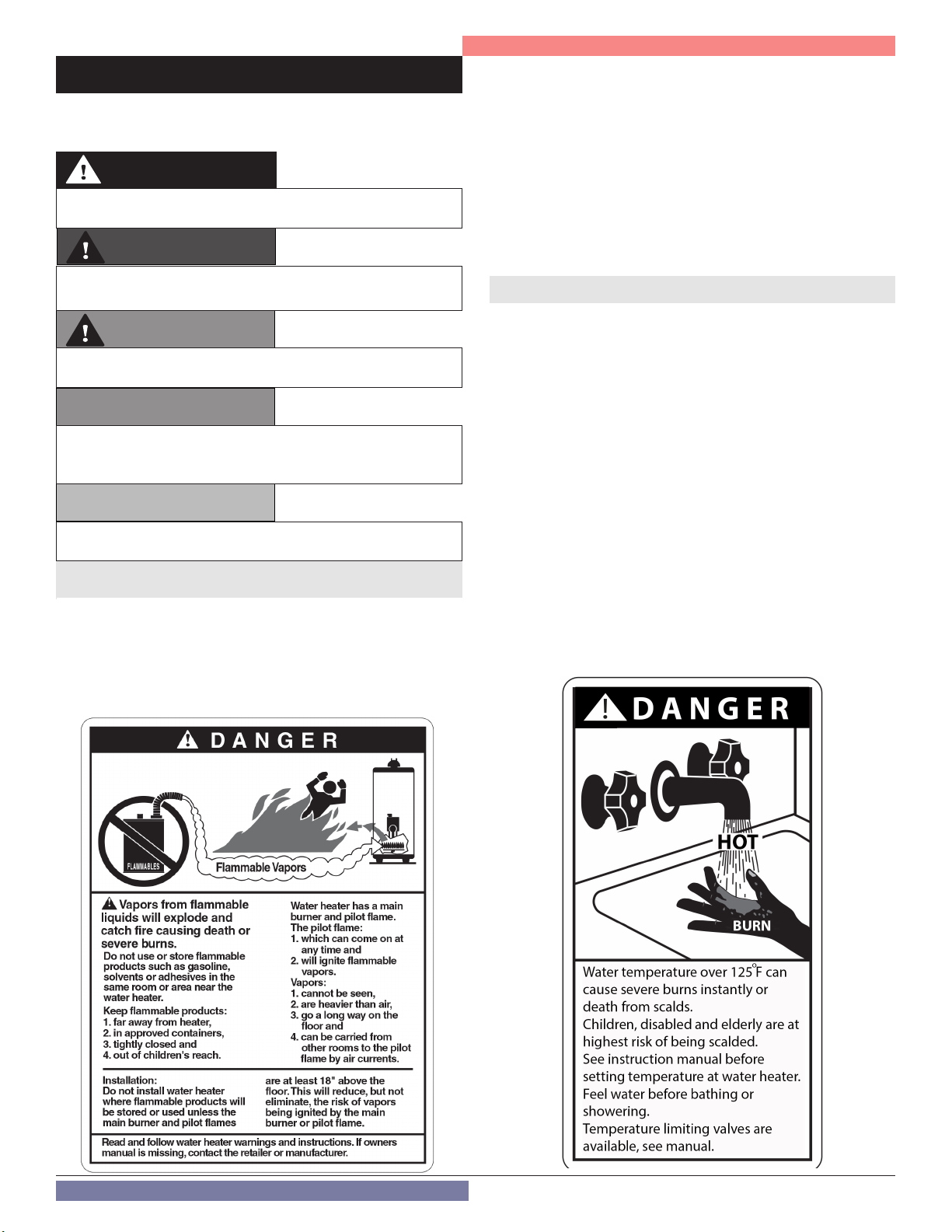
DANGER
Vapors from ammable liquids will explode and cause a re,
resulting in personal injury or death. The boiler has a burner that
can come on at any time and ignite vapors. DO NOT use or store
ammable liquids around the boiler.
Improper venting can cause a build-up of carbon monoxide.
Breathing carbon monoxide can result in brain damage or death.
DO NOT operate the boiler unless it is properly vented to the
outside and has an adequate fresh air supply for safe operation.
Inspect the exterior exhaust gas outlet port and fresh air inlet port
on a regular basis to ensure they are functioning properly.
A concentration of carbon monoxide as small as .04% (400 parts
per million) in the air can be fatal. When making high re or low
re adjustments, CO levels must be monitored using a calibrated
combustion analyzer such that a CO level of no more than 150
ppm is exceeded at any time during operation.
Adjusting the “low re offset” or the “main ow restrictor” in small
increments can result in a signicant increase in CO concentration.
To avoid serious injury or death, DO NOT make any adjustments to
the gas valve without monitoring the exhaust gases with a fully
functional and calibrated combustion analyzer.
Failure to follow these instructions will result in property damage,
severe personal injury, or death.
Make sure the user knows the location of the gas shut-off valve
and how to operate it. Immediately close the gas shut-off valve
if the appliance is subjected to re, overheating, ood, physical
damage, or any other damaging condition that might affect the
operation of the unit. Have the appliance checked by a qualied
service technician before resuming operation.
Do not power up the unit unless the gas and water supply valves
are fully opened. Make sure the fresh air intake port and exhaust
gas port are open and functional.
No one but a qualied service technician should attempt to install,
service, or repair this boiler. There are no serviceable parts which
can be changed by the user / owner.
User / Owner: Contact the original qualied service technician if
the boiler needs repair / maintenance. If the original technician
is unavailable, ask your gas supplier for a list of qualied service
providers.
DO NOT store or place newspapers, laundry, or other combustible
items near the appliance or the exterior exhaust gas outlet and/or
fresh air inlet port.
The owner should inspect the system monthly for damage, water
stains, signs of rust, corrosion, and exhaust vent and air intake
blockage. If inspection of the unit shows signs of damage, the
boiler should be shut off until the problem is repaired by a qualied
technician.
After installation, all appliance safety devices should be tested.
The boiler is certied for indoor installations only. The boiler
consists of gas ignition system components which must be
protected from water (dripping, spraying, etc.) during operation and
service. Carefully consider installation location and the placement
of critical components (circulators, condensate neutralizers, etc.)
before installing the boiler.
DO NOT allow children to operate this boiler. DO NOT use this boiler
if it does not appear to be operating correctly. A qualied service
technician should service and inspect the boiler annually.
NOTE: If the boiler is exposed to re or water (or is any way
damaged), do not operate. Immediately call a qualied service
technician. Failure to follow this information could result in property
damage, severe personal injury, or death.
6
Part 1 - General Safety Information
WARNING
DO NOT USE THIS BOILER IF ANY PART HAS BEEN
SUBMERGED IN WATER. Immediately call a qualied service
technician. The boiler MUST BE replaced if it has been submerged.
Attempting to operate a boiler that has been submerged could
create numerous harmful conditions, such as a potential gas
leakage causing a re and/or explosion, or the release of mold,
bacteria, or other harmful particulates into the air. Operating
a previously submerged boiler could result in property damage,
severe personal injury, or death.
NOTE: Boiler damage due to ood or submersion is considered an
Act of God, and IS NOT covered under product warranty.
WARNING
DO NOT alter or modify the appliance or appliance controls.
Altering any NTI boiler with parts not manufactured by NTI WILL
INSTANTLY VOID the boiler warranty and could result in property
damage, personal injury, or death.
CAUTION
Due to the low water content of the boiler, improper sizing of the
boiler with regard to heating system load will result in excessive
cycling and accelerated component failure. DO NOT under or
oversize the boiler to the system. Modular boiler installations
greatly reduce the likelihood of boiler oversizing. NTI DOES NOT
warrant failures caused by improperly sized boiler applications.
High heat sources (sources generating heat 100oF / 37oC or
greater, such as stove pipes, space heaters, etc.) may damage
plastic components of the boiler as well as plastic vent pipe
materials. Such damages ARE NOT covered by warranty. It is
recommended to keep a minimum clearance of 8” from high heat
sources. Observe heat source manufacturer instructions, as well
as local, state, provincial, and national codes, laws, regulations
and ordinances when installing this boiler and related components
near high heat sources.
B. Improper Combustion
WARNING
Do not obstruct the ow of combustion and ventilating air.
Adequate air is necessary for safe operation. Failure to keep the
exhaust vent and combustion air intake clear of ice, snow, or other
debris could result in property damage, serious personal injury, or
death.
C. Gas
Should overheating or gas supply fail to shut off, turn off the manual
gas control valve to the boiler.
D. When Servicing the Boiler
WARNING
Be sure to disconnect electrical power before opening boiler
cabinet or performing service. Label all wires while performing
service to ensure proper re-wiring of the appliance. Wiring errors
can cause improper or dangerous operation. Failure to do so could
result in electrical shock, improper boiler or system operation,
property damage, serious personal injury, or death.
• To avoid electric shock, disconnect electrical supply before
performing maintenance.
• To avoid severe burns, allow boiler and associated equipment
to cool before servicing.
• Do not use petroleum-based cleaning or sealing compounds
in boiler system. Gaskets and seals in the system may be
damaged, possibly resulting in substantial property damage.
• Do not use “homemade cures” or “boiler patent medicines”.
Substantial property damage, damage to boiler, and/or serious
personal injury may result.
• Always verify proper operation after servicing the boiler.
NOTE: When inquiring about service or troubleshooting, reference the
model and serial numbers from the boiler rating label.
Do not use this boiler for anything other than its intended purpose
(as described in this manual). Doing so could result in property
damage and WILL VOID product warranty.
NOTICE
This appliance is equipped with a three prong plug. It should only be
plugged directly into a properly grounded three prong receptacle.
DO NOT remove the ground plug from the plug.
This appliance provides an overheat shutdown limit. In the event the
appliance water temperature exceeds the setpoint of the control
limit, the cutoff will trip and the appliance will shut down. Certain
local codes require additional temperature limits. In addition,
certain types of systems may operate at temperatures below the
minimum setpoint of the limit provided with the appliance. Contact
the manufacturer for additional overheat controls.
E. Boiler System
• Thoroughly flush the system (without the boiler connected)
to remove sediment. The high-efficiency heat exchanger can
be damaged by build-up or corrosion due to sediment. The
manufacturer recommends a suction strainer in this type of
system.
• Do not use petroleum-based cleaning or sealing compounds
in boiler system. Gaskets and seals in the system may be
damaged, possibly resulting in substantial property damage.
• Do not use “homemade cures” or “boiler patent medicines”.
Substantial property damage, damage to boiler, and/or serious
personal injury may result.
• Continual fresh make-up water will reduce boiler life. Mineral
buildup in the heat exchanger reduces heat transfer, overheats
the stainless steel heat exchanger, and causes failure. Addition
of oxygen from make-up water can cause internal corrosion
in system components. Leaks in the boiler or piping must be
repaired at once.
NOTE: DO NOT add cold make up water to the system when the
boiler is hot. Thermal shock can potentially cause cracks in the heat
exchanger. Such damage IS NOT covered by warranty.
7
Part 1 - General Safety Information
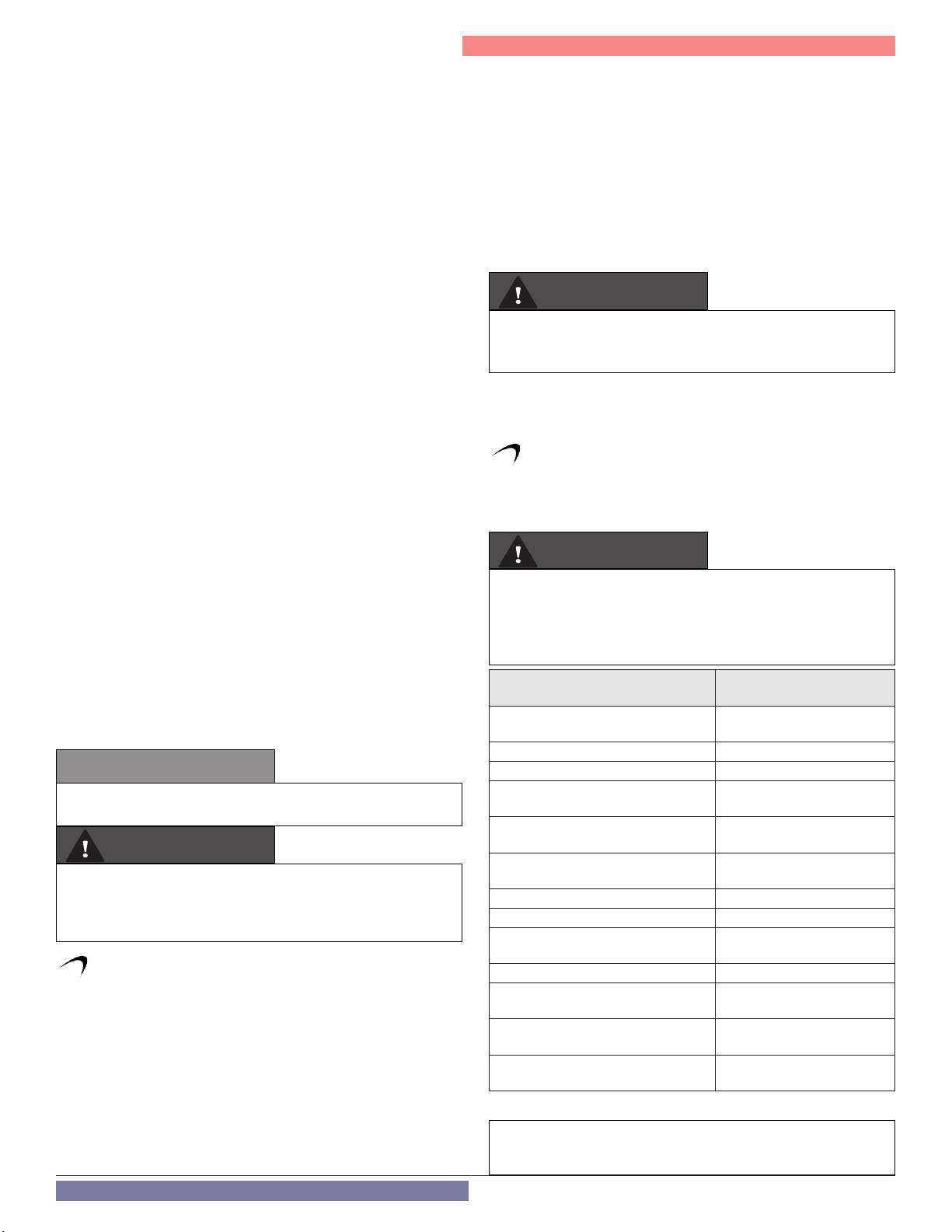
F. CH and DHW Loop Water Chemistry Requirements
CAUTION
Chemical imbalance of the water supply may affect efciency and
cause severe damage to the boiler and associated equipment.
Water quality must be professionally analyzed to determine
whether it is necessary to treat the water. Various solutions are
available to adjust water quality. Adverse water quality will affect
the reliability of the system. In addition, operating temperatures
above 135oF will accelerate the build-up of lime scale and possibly
shorten boiler service life. Failure of a boiler due to lime scale
build-up, low pH, or other chemical imbalance IS NOT covered by
the warranty.
The water must be potable, free of corrosive chemicals, sand,
dirt, and other contaminates. It is up to the installer to ensure the
water does not contain corrosive chemicals or elements that can
damage the heat exchanger. Potable water is dened as drinkable
water supplied from utility or well water in compliance with EPA
secondary maximum contaminant levels (40 CFR Part 143.3). If
the water contains contaminants higher than outlined by the EPA,
water treatment is recommended and additional, more frequent
maintenance may be required. See Table 1.
If you suspect that your water is contaminated in any way,
discontinue use of the appliance and contact an authorized
technician or licensed professional.
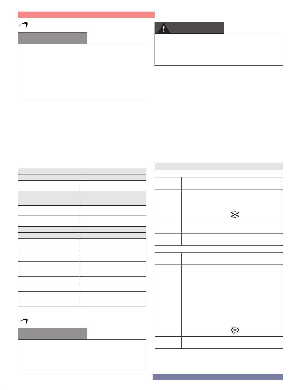
CH Loop Total Water Hardness Specifications
Contaminant Maximum Allowable Level
Total Hardness
DHW Loop Total Water Hardness Specifications
Contaminant Maximum Allowable Level
Total Hardness
(Below 140oF water temperature)
Total Hardness
(Above 140oF water temperature)
CH and DHW Loop Water Quality Specifications
Contaminant Maximum Allowable Level
Aluminum 0.05 to 0.2 mg/l or PPM
Chloride 100 mg/l or PPM
Copper 1 mg/l or PPM
Iron 0.3 mg/l or PPM
Manganese 0.05 mg/l or PPM
pH 6.5 - 8.5
Sulfate 205 mg/l or PPM
Total Dissolved Solids (TDS) 500 mg/l or PPM
Zinc 5 mg/l or PPM
Dissolved Carbon Dioxide (CO2) 15 mg/l or PPM
Table 1 - Water Quality Specifications
G. Freeze Protection
120 mg/l
(7 grains/gallon)
200 mg/l
(12 grains/gallon)
120 mg/l
(7 grains/gallon)
WARNING
NEVER use any toxic chemical, including automotive, standard
glycol antifreeze, or ethylene glycol made for hydronic (nonpotable) systems. These chemicals can attack gaskets and seals in
water systems, are poisonous if consumed, and can cause personal
injury or death.
NOTE: Loops Serving Indirect Water Heaters (IWHs)
Glycol used in IWH loops should be food grade propylene glycol,
FDA rated as “generally recognized as safe” (GRAS). If using a glycol /
potable water mix, the water chemistry must meet the requirements
in this manual. The glycol content of the liquid must not exceed 50%,
unless the manufacturer specifies a different ratio. Glycol should be
checked periodically to prevent it from becoming acidic. Please refer
to guidelines provided by the glycol manufacturer regarding glycol
maintenance.
NOTE: Glycol not recognized as GRAS may only be used in closed loop
CH applications.
NOTE: NTI DOES NOT WARRANT THE BOILER AGAINST FREEZE-RELATED
DAMAGE.
The boiler control is equipped with freeze protection that activates
based on internal water temperature. See the following table for
details on freeze protection operation.
NOTE: Freeze protection will not be active if the boiler loses power.
FREEZE PROTECTION OPERATION
STAGE 1
Condition
Events
Time
Condition
Events
The water temperature detected by probes NTC1 or
NTC2 ranges between 39oF (4oC) and 46oF (8oC).
• The internal pump operates at high speed.
• The 3-Way Valve alternately switches positions - 1
minute on heating mode to 1 minute on DHW
mode
• The display shows the icon.
Until the NTC1 and NTC2 temperature is greater than or
equal to 46°F (8°C)
If after 20 minutes the conditions described in Stage 1
are still present, the boiler proceeds to Stage 2.
STAGE 2
The water temperature detected by probes NTC1 or
NTC2 is less than 39oF (4oC).
• The burner turns on at minimum power.
• The 3-Way Valve is positioned on DHW and
switches every 30 seconds between CH and DHW.
• When the temperature is greater than or equal to
104oF (40oC) the burner will turn off. The boiler will
maintain the temperature between 95oF (35oC)
and 104oF (40oC) for 45 minutes.
• After 45 minutes there will be 2 minutes of post
heating circulation.
• If the temperature falls below 46oF (8oC) within
150 minutes the burner will immediately power on
again.
CAUTION
Consider piping and installation when determining boiler location.
Damages resulting from incorrect installation or from use of
products not approved by the manufacturer ARE NOT covered by
warranty. Failure of the boiler due to freeze related damage IS NOT
covered by product warranty.
8
• The display shows the icon.
Time
Table 2 - Freeze Protection Detail
Until the NTC1 temperature is greater than or equal to
104oF (40oC)
Part 1 - General Safety Information
CAUTION
On TRX085 / TRX120 Models ONLY
If the boiler to be used only in Heating Mode (not connected
to an indirect water heater), the electrical connection of
the 3-way valve motor MUST BE DISCONNECTED while
the boiler is operating in central heating mode. This will
lock the valve motor in central heating mode and ensure
freeze protection operates properly. Failure to disconnect
the valve may disable boiler freeze protection and result
in property damage.
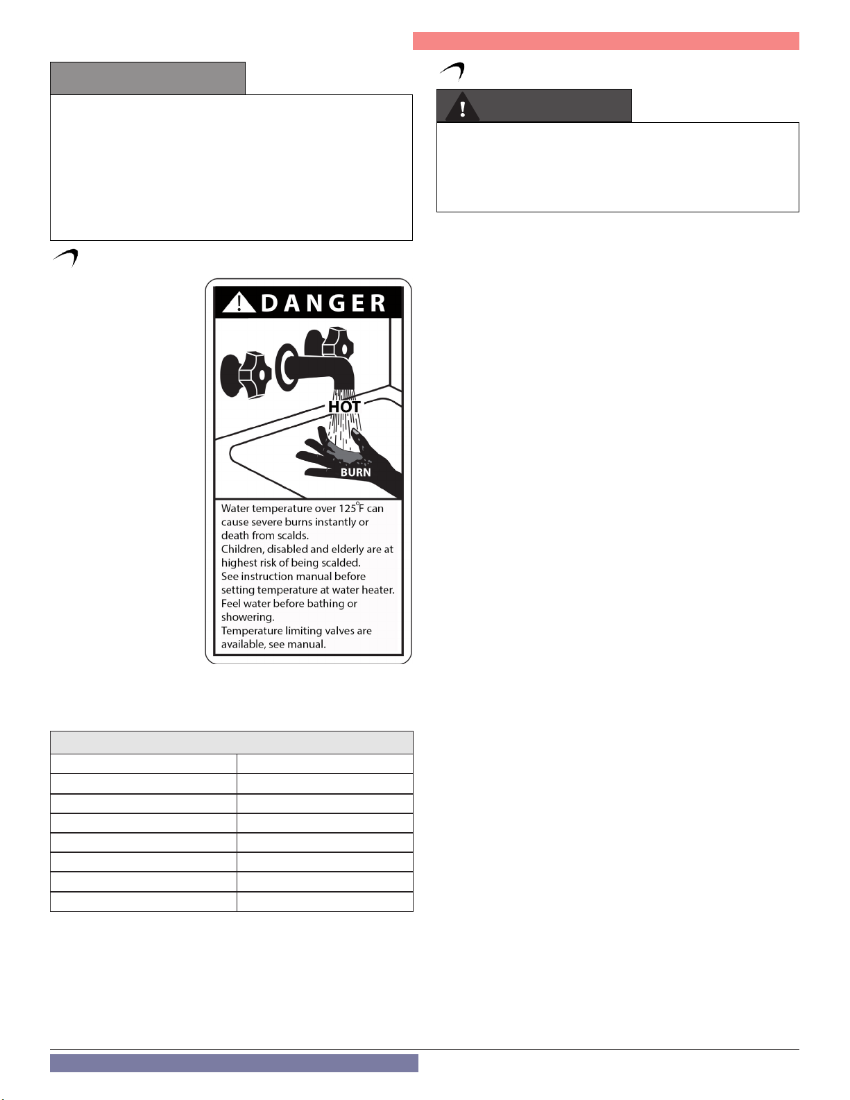
H. Water Temperature Adjustment and Scalding
This boiler can deliver
scalding water. Be careful
whenever using hot water
to avoid scalding injury.
Certain appliances such as
dishwashers and automatic
clothes washers may
require increased water
temperatures. By setting the
thermostat on this boiler to
obtain the increased water
temperature required by
these appliances you may
create the potential for scald
injury.
To protect against injury,
install a mixing valve in the
water system. This valve
will reduce point of use
discharge temperatures by
mixing cold and hot water
in branch supply lines.
Such valves are available
from your local plumbing
supplier.
Table 3 details the
relationship of water temperature and time with regard to scald
injury and may be used as a guide in determining the safest water
temperature for your applications.
I. High Elevation Installations
WARNING
Natural gas at high elevation might contain less heating value than
typical 1,000 BTU/cu ft and therefore can cause improper air / gas
mix leading to improper combustion. For natural gas installations
above 3,000 ft, call your gas provider to determine the heating
value of the supplied natural gas.
Approximate Time / Temperature Relationships in Scalds
120oF More than 5 minutes
125oF 1 1/2 to 2 minutes
130oF About 30 seconds
135oF About 10 seconds
140oF Less than 5 seconds
145oF Less than 3 seconds
150oF About 1 1/2 seconds
155oF About 1 second
Table 3 - Time and Temperature Relationship in Scalds
9
Part 2 - Before You Start
NOTICE
UNCRATING THE BOILER - Any claims for damage or shortage
in shipment must be led immediately against the transportation
company by the consignee.
Remove the boiler from the packaging. Remove the accessory box
from the boiler. Take care to place the boiler in a safe location prior to
installation to prevent damage to the mechanical connections.
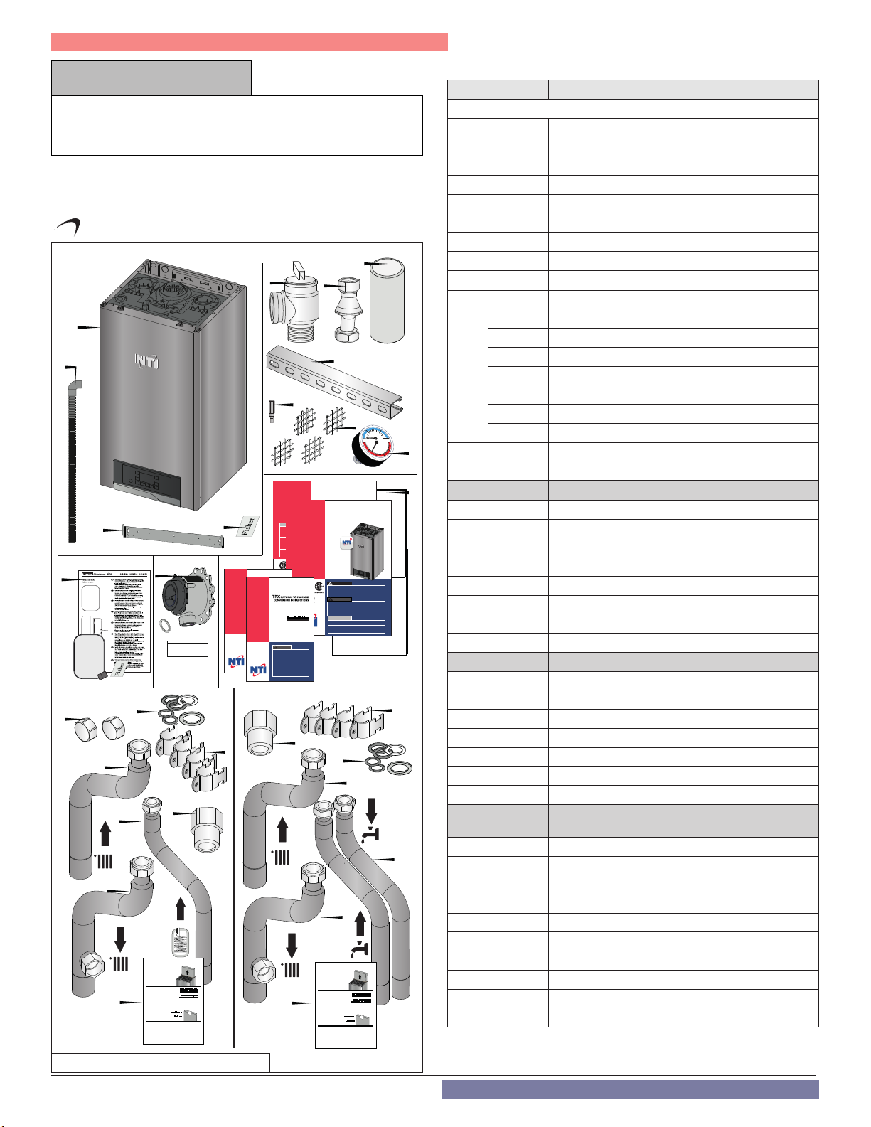
A. What’s in the Box
All models
1
2
3
14b
12
This appliance has been converted for use with Propane Gas, in accordance with the
instructions provided with the Natural to Propane Conversion Kit
by ______________________________________ , which accepts responsibility that
the conversion was performed properly.
THIS CONTROL WAS CONVERTED FOR USE WITH PROPANE GAS
Reference rating plate for Propane Input and Gas Pressure
13
14 15
TRX085
14a
4
Connectivity
Quick Start Guide
TRX series
420060882600
14c
14f
14g
14d
Gas
14e
ACCESSORIES BOX
BOITE ACCESSOIRES
For Qualified Technician
Installation Instructions
14h
Pour technicien qualifié
instructions d’installation
code
Read the code
Lire le code
5
TRX NATURAL TO PROPANE
CONVERSION INSTRUCTIONS
WARNING
This conversion kit shall be installed by a qualified
service agency in accordance with the manufacturer’s
instructions and all applicable codes and requirements
of the authority having jurisdiction. If the information
in these instructions is not followed exactly, a fire, an
explosion or production of carbon monoxide may result
causing property damage, personal injury or loss of
life. The qualified service agency is responsible for the
proper installation of this kit. THE INSTALLATION IS NOT
PROPER AND COMPLETE UNTIL THE OPERATION OF THE
CONVERTED APPLIANCE IS CHECKED AS SPECIFIED IN
THE MANUFACTURER’S INSTRUCTIONS SUPPLIED WITH
THE KIT, WHICH NECESSITATES THE USE OF A CALIBRATED
CO2/O2 AND CO COMBUSTION ANALYZER.
TRX110C
15c
Gas
8
User’s
Information
Manual
Installation
User Operating
Instructions
Start-Up
Maintenance
NOTICE
Parts
The manufacturer reserves the right
to make product changes or updates
without notice and will not be held
Warranty
liable for typographical errors in
literature.
The surfaces of these products
contacted by potable (consumable)
water contain less than 0.25% lead by
weight as required by the Safe Drinking
Water Act, Section 1417.
NOTE TO CONSUMER:
PLEASE KEEP ALL INSTRUCTIONS
FOR FUTURE REFERENCE.
For Qualified Technician
Installation Instructions
15g
Residential Condensing Gas Boiler
Heat Exchanger Bears the ASME “H” Stamp
WARNING
IF THE INFORMATION IN THIS MANUAL IS NOT FOLLOWED EXACTLY,
A FIRE OR EXPLOSION MAY RESULT, CAUSING PROPERTY DAMAGE,
PERSONAL INJURY, OR LOSS OF LIFE. DO NOT STORE GASOLINE OR
OTHER FLAMMABLE VAPORS AND LIQUIDS IN THE VICINITY OF THIS OR
ANY OTHER BOILER.
• Do not try to light any boiler.
• Do not touch any electrical switch.
• Do not use any phone in your building.
• Immediately call your gas supplier from a neighbor’s phone. Follow the
gas supplier’s instructions.
• If you cannot reach your gas supplier, call the fire department.
Installation and service must be provided by a qualified installer,
service agency, or the gas supplier.
Improper installation, adjustment, alteration, service, or maintenance could
void product warranty and cause property damage, severe personal injury,
or death.
California Proposition 65 Warning: This product contains chemicals
known to the State of California to cause cancer, bir th defects, or other
reproductive harm.
15d
ACCESSORIES BOX
BOITE ACCESSOIRES
5
7
9
TRX
TRX
Residential Condensing Gas Boiler
Heat Exchanger Bears the ASME “H” Stamp
WHAT TO DO IF YOU SMELL GAS
DANGER
THIS MANUAL MUST ONLY BE USED BY A QUALIFIED INSTALLER /
SERVICE TECHNICIAN. READ ALL INSTRUCTIONS IN THIS MANUAL
BEFORE INSTALLING. PERFORM STEPS IN THE GIVEN ORDER. FAILURE
TO DO SO COULD RESULT IN SUBSTANTIAL PROPERTY DAMAGE, SEVERE
PERSONAL INJURY, OR DEATH.
WARNING
Improper installation, adjustment, alteration, service, or maintenance
could void product warranty and cause property damage, severe
personal injury, or death.
California Proposition 65 Warning: This product contains chemicals
known to the State of California to cause cancer, birth defects, or
other reproductive harm.
NOTICE
The manufacturer reserves the right to make product changes or updates
without notice and will not be held liable for typographical errors in literature.
The surfaces of these products contacted by potable (consumable) water
contain less than 0.25% lead by weight as required by the Safe Drinking Water
Act, Section 1417.
15a
15e
For Qualified Technician
Installation Instructions
Pour technicien qualifié
instructions d’installation
code
Read the code
Lire le code
6
20
0
20
0 250
50
TRX
TRX
40
60
psi
80
200
100 150
15b
15f
10
11
QSG
TEMPLATE
Components included with the boiler:
Nr. Quantity Description
ALL MODELS
1 1 Condensing Gas Boiler
2 1 Condensate Drain Pipe
3 1 Bracket
4 2 Assembly Screws (Fischer Type SX )
5 1+1 CH Pressure Relief Valve + Connection Tube
6 1 2” CPVC Pipe, 5.5” Long
7 1 Piping Bracket
8 1 Torx screw adapter
9 2 + 2 2” Vent Screen + 3” Vent Screen
10 1 Tridicator
1 Installation Manual (This Document)
1 User’s Information Manual
1 Connectivity Quick Start Guide
11
12 1 LP Gas Conversion Kit
13 1 Outdoor sensor Kit
14 1 Piping Adapter Kit - TRX085
14-a 2 Cap 1/2”
14-b 6 Gasket (2x1/2” + 2x3/4” + 1 x 1” + 1 gas fiber)
14-c 4 Clamp (2x3/4” + 2x1”)
14-d 1 Gas Adapter 3/4”
14-e 1 CH supply pipe 1”
14-f 1 CH return pipe 1”
14-g 1 Tank return pipe 3/4”
14-h 1 Accessory box components list
15 1 Piping Adapter Kit- TRX110C
15-a 6 Gasket (2x1/2” + 2x3/4” + 1 x 1” + 1 gas fiber)
15-b 4 Clamp (2x3/4” + 2x1”)
15-c 1 Gas Adapter 3/4”
15-d 1 CH supply pipe 1”
15-e 1 CH return pipe 1”
15-f 2 DHW outlet & inlet pipes 3/4”
15-g 1 Accessory box components list
16 1
16-a 7 Gasket (2x1/2” + 3x3/4” + 1 x 1” + 1 gas fiber)
16-b 4 Clamp (2x3/4” + 2x1”)
16-c 1 Gas Adapter 3/4”
16-d 1 CH supply pipe 1”
16-e 1 CH return pipe 1”
16-f 1 DHW outlet pipe (150C)/Tank return pipe (120) 3/4”
16-g 1 DHW inlet flow restrictor (150C)1/2” x 3/4”
16-h 1 DHW inlet pipe 3/4”
16-i 2 Cap 1/2”
16-j 2 Accessory box components list
Table 4 - Included with the Boiler
1 LP Convertion Instructions
1 Warranty
1 Installation Quick Start Guide
1 Template
Piping Adapter Kit - TRX1120/ TRX150C
(see fig. 1 part b - next page)
Figure 1 - Included with the Boiler - part a
10
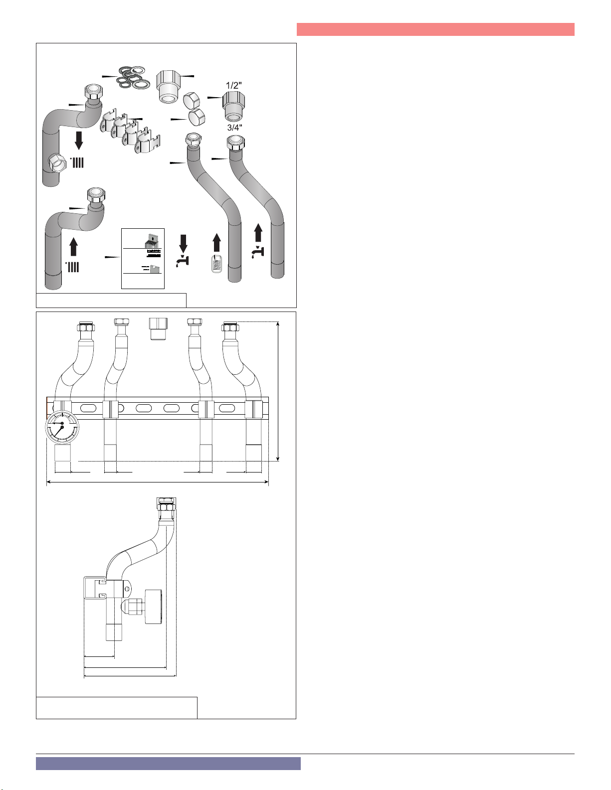
TRX150C / TRX120
14a
16d
16b
16i
16f
16e
ACCESSORIES BOX
BOITE ACCESSOIRES
For Qualified Technician
16j
Installation Instructions
Pour technicien qualifié
instructions d’installation
code
Read the code
Lire le code
Figure 2 - Included with the Boiler - part b
40
60
20
psi
80
0
20
0
250
200
50
100 150
View from
the Front
Ø 1-1/8”
2-3/16” (55 mm)
6-3/8” (162 mm)
6-11/16” (169 mm)
16” (406 mm)
View from the Side
Figure 3 - Adapter Kit Dimensions and
Specifications - Included with Adapter Kit
16c
or
16g
16h
Part 2 - Before You Start
How the Boiler Operates
TRX condensing technology intelligently delivers hydronic heating
while maximizing efficiency. Outlined below are system features and
operation:
Stainless Steel Heat Exchanger
The highly efficient stainless steel heat exchanger is designed to
extract all available heat from the supply line before it is exhausted.
Modulating Combustion System
The combustion system modulates the output of the burner during
operation to match system demand and achieve the control set point
while in operation. The set point can change by internal or external
signals to enhance the overall performance of the system.
Control
The integrated control system monitors the system and regulates fan
speed to control boiler output. This allows the boiler to deliver only the
amount of heat energy required and nothing more.
The control can be set to monitor outdoor temperature through an
outdoor sensor to regulate boiler set point. The system can be further
enhanced by installing an indirect water heater to provide domestic
hot water.
The control can regulate the output of multiple boilers through its
cascade system function. The cascade system is capable of connecting
up to eight boilers together in such a way that they function as one
boiler system. This allows for greater turn down ratios and provides
systematic control of the multiple boilers in an installation to minimize
downtime and maximize efficiency.
The cascade system works by establishing one boiler as the master and
the other connected boilers as followers. The master boiler requires
a sensor to provide feedback on set point temperature in order to
adjust heating input from the connected boilers. Each cascaded boiler
will have its own pump to provide maximum flow and control heat
exchanger flow rate.
10" 1/16” (255 mm)
Ø 1-1/8” Ø 7/8” Ø 7/8”
Text Display and Operational Display Icons
The display allows the user to change system parameters and monitor
system outputs.
Gas Valve
Senses suction from the blower, allowing gas to flow only if powered
and combustion air is flowing.
Integrated Venturi
Controls air and gas flow into the burner.
Burner
The high grade stainless steel burner uses premixed air and gas to
provide a wide range of firing rates.
Spark Ignition
The burner is ignited by applying high voltage through the system
spark electrode. The spark from the electrode ignites mixed gas off of
the burner.
Supply Water Temperature Sensor
This sensor monitors the boiler outlet water temperature (System
Supply). The control adjusts boiler firing rate so the supply temperature
will match the boiler set point.
Return Water Temperature Sensor
This sensor monitors boiler return water temperature (System Return).
Flue Sensor
Monitors flue temperature and adjusts firing rate.
Temperature and Pressure Gauge
Allows the user to monitor system temperature and pressure.
Electrical field connections with terminal strips
The electrical cover allows easy access to the clearly marked line
voltage and low voltage terminal strips to facilitate wiring the boiler.
11

Part 2 - Before You Start
Condensate Collection System
This boiler is a high efficiency appliance and will produce condensate.
The condensate collection system has a float switch which monitors
condensate level and prevents condensate from backing up into the
combustion system. Inside the collection system is a built in trap
which seals the combustion system from the connected drain. This
condensate should be neutralized to avoid damage to the drainage
system or piping.
Outdoor Sensor
Monitors outdoor temperature and adjusts unit set point to provide
greater efficiency.
0-10 Volt Input / 4-20 mA Input (with Optional Connection Card)
Allows the installer to connect a BMS (Building Management System)
to control the boiler.
Condensate Trap and Air Pressure Switch
The condensate trap and air pressure switch prevent condensate and
heat exchanger exhaust from backing up into the boiler.
Pump Service Mode
Allows manual operation of pumps to commission system and check
pump operation.
Internal By-Pass Valve
Protects the boiler from damage in low flow conditions.
Internal ECM Pump
The internal ECM Pump uses less electricity than standard pumps,
providing high performance operation.
B. Optional Equipment
Optional equipment available from NTI (and Part #):
• System Sensor (84010)
• 3” PVC Concentric Vent Kit (84634)
• 3” PVC Low Profile Vent Kit (84357)
• 2” PVC Low Profile Vent Kit (85062)
• Tank Sensor (84632)
NOTE: When using an optional system sensor, pipe insulation must be
wrapped around it to improve temperature measurement accuracy
and increase overall system efficiency.
12
Part 3 - Prepare the Boiler for Installation
CAUTION CAUTION
COLD WEATHER HANDLING - If the boiler has been stored in
a very cold location (BELOW 0oF) before installation, handle with
care until the components come to room temperature. Failure to
do so could result in damage to the boiler.
Carefully consider installation when determining boiler location.
Please read the entire manual before attempting installation.
Failure to properly take factors such as boiler venting, piping,
condensate removal, and wiring into account before installation
could result in wasted time, money, and possible property damage
and personal injury.
A. Locating the Boiler
WARNING
This boiler is certied for indoor use only. DO NOT INSTALL
OUTDOORS. Outdoor installations ARE NOT covered by warranty.
Failure to install the boiler indoors could result in property damage,
severe personal injury, or death.
Incorrect ambient conditions can lead to damage to the heating
system and put safe operation at risk. Ensure that the installation
location adheres to the information included in this manual. Failure
to do so could result in property damage, serious personal injury,
or death. Failure of boiler or components due to incorrect operating
conditions IS NOT covered by product warranty.
This boiler must be installed upright in the vertical position as
described in this manual. DO NOT attempt to install this boiler in any
other orientation. Doing so will result in improper boiler operation
and property damage, and could result in serious personal injury
or death.
1. Installation Area (Mechanical Room) Operating Conditions
• Ensure ambient temperatures are higher than 32oF / 0oC and
lower than 104oF / 40oC
• Prevent the air from becoming contaminated by the products,
places, and conditions listed in this manual
• Avoid continuously high levels of humidity
• Never close existing ventilation openings
• Ensure a minimum 1” clearance around hot water and exhaust
vent pipes
• NOTE: To prevent condensing in the fan, it is recommended to
avoid prolonged exposure to temperatures below 45oF
The service life of the boiler’s exposed metallic surfaces, such
as the casing, as well as internal surfaces, such as the heat
exchanger, are directly inuenced by proximity to damp and salty
marine environments. In such areas higher concentration levels of
chlorides from sea spray coupled with relative humidity can lead to
degradation of boiler components. In these environments, boilers
must not be installed using direct vent systems which draw outdoor
air for combustion. Such boilers must be installed using room air
for combustion. Indoor air will have a much lower relative humidity,
and hence potential corrosion will be minimized.
Failure of the boiler or components due to incorrect operating
conditions IS NOT covered by product warranty.
2. Check for nearby connections to:
• System water piping
• Venting connections
• Gas supply piping
• Electrical power
• Condensate drain
3. Check area around boiler. Remove any combustible materials,
gasoline, and other flammable liquids.
WARNING
Failure to keep the boiler area clear and free of combustible
materials, liquids, and vapors can result in substantial property
damage, severe personal injury, or death.
4. Gas control system components must be protected from dripping
water during operation and service.
5. If the boiler is to replace an existing boiler, check for and correct any
existing system problems, such as:
• System leaks
• Location that could cause the system and boiler to freeze and
leak
• Incorrectly sized expansion tank
CAUTION
Always take future maintenance into consideration when locating
the boiler. If the boiler is located in an installation location with
limited clearances, it may be necessary to remove the boiler
from the space to perform maintenance. Failure to consider
maintenance when determining installation location could result in
property damage.
WARNING
This boiler has a condensate disposal system that may freeze
if exposed to sustained temperatures below 32oF. Precautions
should be taken to protect the condensate trap and drain lines
from sustained freezing conditions.
WARNING
Circulators suitable for DHW applications must be used.
Failure to take precautions could result in property damage, severe
personal injury, or death.
6. Clean and flush system when reinstalling a boiler.
WARNING
Do not introduce toxic chemicals, such as antifreeze or appliance
treatments, into any piping meant for potable water purposes.
Do not connect the appliance DHW connections to any heating
systems or components that have been previously used for
nonpotable applications.
Ensure that all piping and components connected to the appliance
are suitable for potable water applications.
Failure to follow these instructions could result in serious personal
injury or death.
13
Part 3 - Prepare the Boiler for Installation
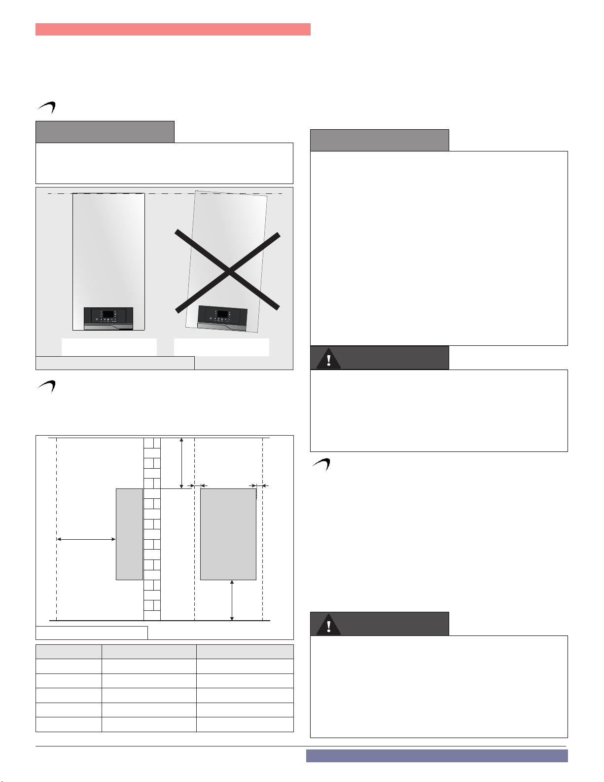
Correct installation
Incorrect installation
NOTE: When installing in a zero clearance location, it may not be
possible to read or view some product labeling. It is recommended to
make note of the boiler model and serial number.
NOTE: A combustible door or removable panel is acceptable front
clearance.
B. Leveling
NOTE: For closet installations, a combustible door or removable
panel is acceptable front clearance. A 3” minimum clearance must be
provided from the appliance front cover to the removable panel or
combustible door.
Minimum Clearances from Combustible Materials
• Hot water pipes - at least 1” from combustible materials
• Exhaust vent pipe - at least 1” from combustible materials
CAUTION
In order for the condensate to properly ow out of the collection
system, the area where you locate the boiler must be level. Failure
to do so will result in improper appliance operation.
Figure 4 - Proper levelling
C. Clearances for Service Access
NOTE: If you do not provide the minimum clearances shown in Figure
5 and Table 5 it might not be possible to service the boiler without
removing it from the space.
CAUTION
All boilers eventually leak. Locate the boiler where any leakage from
the relief valve, related piping, tank, or connections will not result
in damage to surrounding areas or lower oors of the building. Any
boiler should be installed in such a manner that if it should leak
the resulting ow of water will not cause damage to the area in
which it is installed. If the boiler is installed in a location where
a leak could cause damage, it is required to provide containment
measures. Such measures include but are not limited to: a properly
sized drain pan installed beneath the boiler and piped to an open
drain line, or installing the boiler on a concrete oor pitched to a
free owing drain. Failure to provide containment measures is the
sole responsibility of the owner and/or installer. Leakage damages
ARE NOT covered by warranty.
In addition, water leak detection devices and automatic water
shutoff valves are readily available at plumbing supply houses. IT
IS HIGHLY RECOMMENDED BY THE MANUFACTURER TO INSTALL
WATER LEAK DETECTION DEVICES AND AUTOMATIC SHUTOFF
VALVES IN ANY BOILER INSTALLATION WHERE A LEAKAGE OF
WATER COULD RESULT IN PROPERTY DAMAGES.
WARNING
The space must be provided with combustion / ventilation air
openings correctly sized for all other appliances located in the same
space as the boiler. The boiler cover must be securely fastened to
prevent the boiler from drawing air from the boiler room. This is
particularly important if the boiler is in a room with other appliances.
Failure to comply with the above warnings could result in substantial
property damage, severe personal injury, or death.
A
B B
C
D
Figure 5 - Minimum Clearances
Dimension Description Clearance
A Top 14” (355.6 mm)
B Right or Left Side 2” (50.8 mm)
C Front 18” (457.2 mm)
D Bottom 12” (304.8 mm)
Not Displayed Back 0” (0 mm)
Table 5 - Minimum Installation and Service Clearances
14
D. Wall Mounting Considerations
These boilers are wall mounted. Use only the wall mounting instructions
included with this boiler.
Ensure the wall that the boiler is intended to be mounted on is
comprised of cement, brick, block, or wooden studs spaced 16” apart
from center. Ensure the wall is capable of supporting at least 150 lbs
(68 kgs).
If flooding is possible, elevate the boiler to prevent floodwater from
reaching the boiler.
Ensure the boiler is installed in a location that minimizes the risk of
water damage due to leaking valves, pumps, unions, etc.
The boiler may be installed on any suitable internal wall (suitable soundproofing may be required when installing onto a stud partition wall).
WARNING
Ensure that the structure of the installation location is sufcient to
support the full installed weight of the boiler, including water content
of the heat exchanger and related piping and components. If the
mounting location cannot support a minimum of 150 lbs. (68 kg), it
is recommended to locate the boiler in a mounting location that can
support the minimum weight. Failure to ensure the structure of the
installation location is structurally sound before installation of the
boiler and properly mount the boiler can result in structural failure,
substantial property damage, severe personal injury, or death.
WARNING
Do not mount the boiler to a hollow wall.
E. Wall Mounting Instructions
WARNING
This boiler is too heavy for one person to lift. It is highly recommended
to install the boiler with two people. Use caution as to not drop the
boiler, which could damage the boiler and cause property damage
and/or severe personal injury. Verify that the boiler is properly and
securely mounted before leaving unsupervised. Failure to comply
with the above and properly mount the boiler could result in
substantial property damage, severe personal injury, or death.
1. Mounting to a concrete wall
Position the paper template on the concrete wall to locate the
positions of the hanging bracket and piping bracket.
Drill and plug the wall and secure the hanging bracket using the
screws provided (sher S 10x50). Ensure the hanging bracket is level.
Secure the piping bracket on the concrete wall. Use suitable
hardware.
Part 3 - Prepare the Boiler for Installation
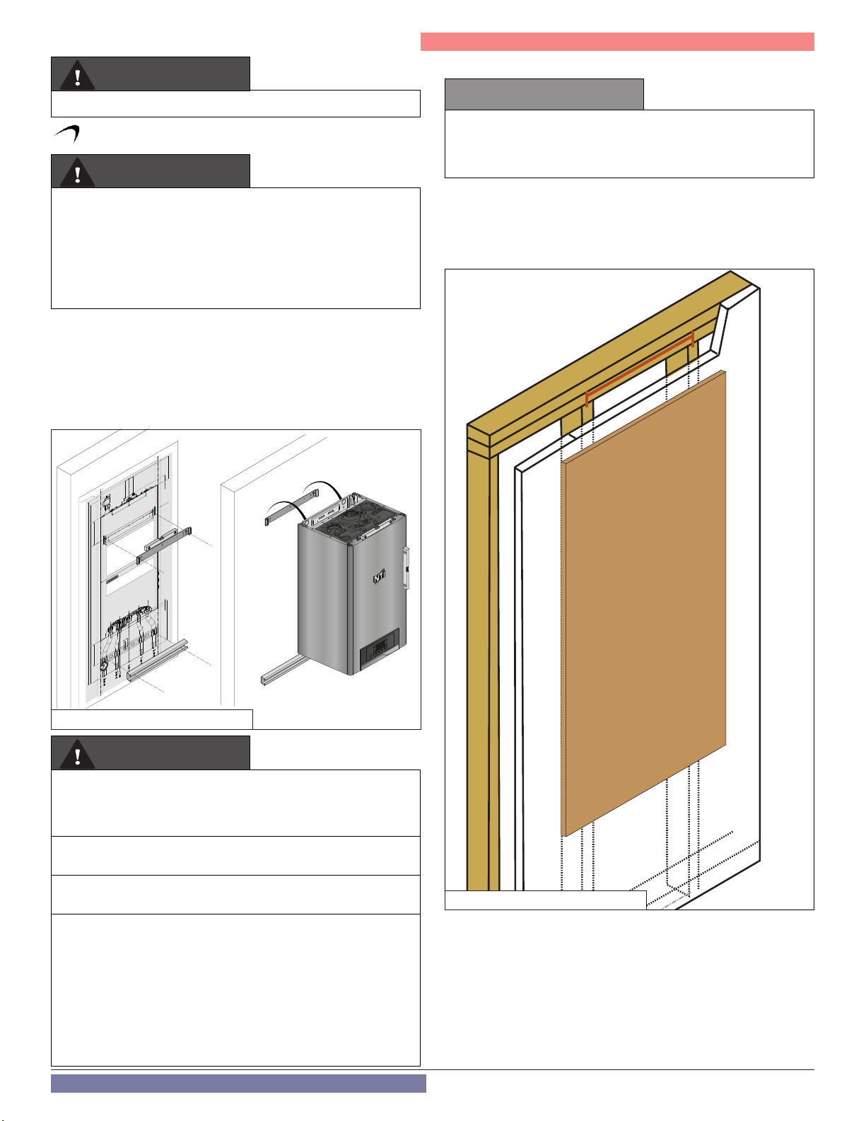
2. Mounting to a Wood Studded Wall
CAUTION
If the boiler is not installed upright, vertically plumb, and level,
improper and unsatisfactory operation may occur, causing excessive
condensation build-up, nuisance fault codes, and unnecessary
maintenance.
To install the boiler on a standard wood studded wall with 16” centers,
a plywood board is required. The minimum dimensions of the plywood
board are: 24” wide x 48” high x 1/2” thick.
Use at least fourteen (14) #12 x 3” (3/16” x 3”) round head tapping
screws to secure the plywood board to the studded wall.
16 “
STUDSTUD
5-3/8”
(136,5 mm)
16”
(406,4 mm)
1-3/8”
2-5/8” 2-5/8”
1-1/8”
(34,2 mm)
(120 mm)
13”
(330 mm)
15-3/4”
(400 mm)
1/2”
(13,1 mm)
2-9/16”
(239,75 mm)
9-7/16”
(67 mm)(67 mm)
9/16”
3-7/16” 3-7/16”
Plywood board
Dimensions:
24" wide x 48" high x 1/2" thick
(110 mm)
4-5/16”
(745 mm)
29-5/16”
43-5/8”
(1108,15 mm)
8-15/16”
(226,65 mm)
5-3/4”
(146,26 mm)
MOUNTING TO A WOOD STUDDED WALL
To install the boiler on a standard wood studded wall a plywood board is required. The minimum
dimensions of the plywood board are: 24" wide x 48" high x 1/2" thick.
Use at least fourteen (14) #12 x 3" (3/16" x 3") round head tapping screws to secure the plywood board to
the studded wall.
WALL MOUNTING INSTRUCTIONS
After the plywood board has been installed to the studs, position the paper template on the plywood.
Locate the positions of the hanging bracket and piping adapter bracket. Position the wall mounting and
piping adapter brackets. Ensure the brackets are level. Then mark the bracket drilling holes.
Mount the boiler bracket on the plywood board. Use the hardware delivered with the boiler
(fisher S 10x50) and washers for wood mounting.
Mount the piping bracket on the plywood board. Use suitable hardware .
Position the paper template on the concrete wall to locate the positions of the hanging bracket and piping
bracket.
Drill and plug the wall and secure the hanging bracket using the screws provided (fisher S 10x50). Ensure
the hanging bracket is level.
Secure the piping bracket on the concrete wall. Use suitable hardware.
WARNING
THE MANUFACTURER CANNOT ANTICIPATE ALL INSTALLATION CONDITIONS. THESE INSTRUCTIONS AND
INCLUDED PARTS MAY NOT APPLY TO WALL-MOUNTING THE BOILER AT YOUR INSTALLATION LOCATION.
THE BOILER MUST BE PROPERLY AND SECURELY MOUNTED BY A QUALIFIED INSTALLER ACCORDING TO
INSTALLATION CONDITIONS, THE TECHNICAL SPECIFICATIONS OF THE APPLIANCE, AND TO MEET AHJ /
BUILDING CODE REQUIREMENTS. ALL APPLICABLE PERMITS MUST BE OBTAINED BEFORE INSTALLING THE
BOILER. FAILURE TO FOLLOW THESE INSTRUCTIONS COULD RESULT IN PROPERTY DAMAGE, SEVERE
PERSONAL INJURY, OR DEATH. ANY DAMAGES RESULTING FROM IMPROPER INSTALLATION ARE NOT
COVERED BY PRODUCT WARRANTY.
2-9/16”
(65 mm) (65 mm)
5-3/16”
(131,76 mm)
60
40
80
psi
20
250
0
200
20
0
50
100 150
3-7/16”
(87,2 mm) (87,2 mm)(87,6 mm) (87,6 mm)
4-3/4” 4-3/4”
(120 mm)
3-7/16”
Figure 6 - Mounting to a concrete wall
WARNING
This wall mounting system is not seismic rated and should not be
applied as such. Failure to comply with the above and properly
mount the boiler could result in substantial property damage,
severe personal injury, or death.
Use extreme care not to drop the boiler or cause bodily injury while
lifting or mounting the boiler onto the wall mount bracket.
Failure to follow these instructions could result in property damage,
severe personal injury, or death.
The manufacturer cannot anticipate all installation conditions. These
instructions and included parts may not apply to wall-mounting
the appliance at your installation location. The appliance must be
properly and securely mounted by a qualied installer according to
installation conditions, the technical specications of the appliance,
and to meet AHJ / building code requirements. All applicable permits
must be obtained before installing the appliance. Failure to follow
these instructions could result in property damage, severe personal
injury, or death. Any damages resulting from improper installation
are not covered by product warranty.
Figure 7 - Mounting a playwood board
15

Part 3 - Prepare the Boiler for Installation
F. Residential Garage and Closet Installations
16 “
Plywood board
Dimensions:
24" wide x 48" high x 1/2" thick
4-5/16”
29-5/16”
43-5/8”
(1108,15 mm)
8-15/16”
16 “
(110 mm)
(745 mm)
(226,65 mm)
(120 mm)
5-3/4”
(146,26 mm)
MOUNTING TO A WOOD STUDDED WALL
To install the boiler on a standard wood studded wall a plywood board is required. The minimum
dimensions of the plywood board are: 24" wide x 48" high x 1/2" thick.
Use at least fourteen (14) #12 x 3" (3/16" x 3") round head tapping screws to secure the plywood board to
the studded wall.
WALL MOUNTING INSTRUCTIONS
After the plywood board has been installed to the studs, position the paper template on the plywood.
Locate the positions of the hanging bracket and piping adapter bracket. Position the wall mounting and
piping adapter brackets. Ensure the brackets are level. Then mark the bracket drilling holes.
Mount the boiler bracket on the plywood board. Use the hardware delivered with the boiler
(fisher S 10x50) and washers for wood mounting.
Mount the piping bracket on the plywood board. Use suitable hardware .
Position the paper template on the concrete wall to locate the positions of the hanging bracket and piping
bracket.
Drill and plug the wall and secure the hanging bracket using the screws provided (fisher S 10x50). Ensure
the hanging bracket is level.
Secure the piping bracket on the concrete wall. Use suitable hardware.
WARNING
THE MANUFACTURER CANNOT ANTICIPATE ALL INSTALLATION CONDITIONS. THESE INSTRUCTIONS AND
INCLUDED PARTS MAY NOT APPLY TO WALL-MOUNTING THE BOILER AT YOUR INSTALLATION LOCATION.
THE BOILER MUST BE PROPERLY AND SECURELY MOUNTED BY A QUALIFIED INSTALLER ACCORDING TO
INSTALLATION CONDITIONS, THE TECHNICAL SPECIFICATIONS OF THE APPLIANCE, AND TO MEET AHJ /
BUILDING CODE REQUIREMENTS. ALL APPLICABLE PERMITS MUST BE OBTAINED BEFORE INSTALLING THE
BOILER. FAILURE TO FOLLOW THESE INSTRUCTIONS COULD RESULT IN PROPERTY DAMAGE, SEVERE
PERSONAL INJURY, OR DEATH. ANY DAMAGES RESULTING FROM IMPROPER INSTALLATION ARE NOT
COVERED BY PRODUCT WARRANTY.
2-9/16”
(65 mm) (65 mm)
5-3/16”
(131,76 mm)
60
40
80
psi
20
250
0
200
20
0
50
100 150
3-7/16”
(87,2 mm) (87,2 mm)(87,6 mm) (87,6 mm)
16”
(406,4 mm)
4-3/4” 4-3/4”
13”
(330 mm)
15-3/4”
(400 mm)
(67 mm)(67 mm)
2-5/8” 2-5/8”
1-1/8”
9/16”
3-7/16”
(120 mm)
2-9/16”
3-7/16” 3-7/16”
STUDSTUD
5-3/8”
(136,5 mm)
1-3/8”
(34,2 mm)
Check with your local Authority Having Jurisdiction for requirements
when installing boiler in a garage or closet. Please read the entire
manual before attempting installation. Failure to properly take
factors such as boiler venting, piping, condensate removal, and
wiring into account before installation could result in wasted time,
money, and possible property damage and personal injury.
Precautions
If the boiler is located in a residential garage, per ANSI Z223.1:
• Mount the bottom of the boiler a minimum of 18” above the
floor of the garage to ensure the burner and ignition devices
are well off the floor.
• Locate or protect the boiler so it cannot be damaged by a
moving vehicle.
WARNING
1/2”
CAUTION
(13,1 mm)
(239,75 mm)
9-7/16”
16 “
The space must be provided with correctly sized combustion/
ventilation air openings for all other appliances located in the space
with the boiler. For power venting installations using room air for
combustion, refer to the boiler venting section, this manual, for
descriptions of conned and unconned spaces. Do not install the
boiler in an attic. Failure to comply with these warnings could result
in substantial property damage, severe personal injury, or death.
G. Exhaust Vent and Intake Pipe
The boiler is rated ANSI Z21.13 Category IV (pressurized vent, likely
to form condensate in the vent) and requires a special vent system
designed for pressurized venting.
NOTE: The venting options described here (and further detailed
in the Venting section, this manual) are the lone venting options
approved for this boiler. Failure to vent the boiler in accordance
with the provided venting instructions will void the warranty.
Figure 8 - Mounting the hanging bracket and piping bracket
After the plywood board has been installed to the studs, position the
paper template on the plywood.
Locate the positions of the hanging bracket and piping adapter
bracket. Position the wall mounting and piping adapter brackets.
Ensure the brackets are level. Then mark the bracket drilling holes.
Mount the boiler bracket on the plywood board. Use the hardware
delivered with the boiler (fisher S 10x50) and washers for wood
mounting.
Mount the piping bracket on the plywood board. Use suitable
hardware .
DANGER
Failure to vent the boiler properly will result in serious personal
injury or death.
WARNING
Do not attempt to vent this boiler by any means other than those
described in this manual. Doing so will void the warranty and may
result in severe personal injury or death.
Vents must be properly supported. Boiler exhaust and intake
connections are not designed to carry heavy weight. Vent support
brackets must be within 1’ of the boiler and the balance at 4’
intervals. Boiler must be readily accessible for visual inspection for
rst 3’ from the boiler. Failure to properly support vents could result
in property damage, severe personal injury, or death.
The exhaust discharged by this boiler may be very hot. Avoid
touching or other direct contact with the exhaust gases of the vent
termination assembly. Doing so could result in severe personal
injury or death.
1. Direct Vent of Exhaust and Intake
If installing a direct vent option, combustion air must be drawn
from the outdoors directly into the boiler intake and exhaust must
terminate outdoors. There are three basic direct vent options detailed
in this manual: 1. Side Wall Venting, 2. Roof Venting, and 3. Unbalanced
16
Venting.
Be sure to locate the boiler such that the exhaust vent and intake
piping can be routed through the building and properly terminated.
Different vent terminals can be used to simplify and eliminate multiple
penetrations in the building structure (see Optional Equipment in
Venting Section). The exhaust vent and intake piping lengths, routing,
and termination methods must all comply with the methods and limits
given in the Venting Section, this manual.
When installing a combustion air intake from outdoors, care must
be taken to utilize uncontaminated combustion air. To prevent
combustion air contamination, see Table 6.
2. Power Venting, Indoor Combustion Air in Confined or
Unconfined Space
This boiler requires fresh, uncontaminated air for safe operation and must
be installed in a mechanical room where there is adequate combustion
and ventilating air. NOTE: To prevent combustion air contamination,
see Table 6.
Combustion air from the indoor space can be used if the space has
adequate area or when air is provided through a duct or louver to supply
sufficient combustion air based on the boiler input. Never obstruct the
supply of combustion air to the boiler. If the boiler is installed in areas
where indoor air is contaminated (see Table 6) it is imperative that the
boiler be installed as direct vent so that all combustion air is taken directly
from the outdoors into the boiler intake connection.
Unconfined space is space with volume greater than 50 cubic feet per
1,000 BTU/hr (4.8 cubic meters per kW) of the total input rating of all fuelburning appliances installed in that space. Rooms connected directly to
this space through openings not furnished with doors are considered part
of the space. See Venting Section for details.
Confined space is space with volume less than 50 cubic feet per 1,000
BTU/hr (4.8 cubic meters per kW) of the total input rating of all fuelburning appliances installed in that space. Rooms connected directly to
this space through openings not furnished with doors are considered part
of the space.
When drawing combustion air from inside a conventionally constructed
building to a confined space, such space should be provided with two
permanent openings: one located 6” (15 cm) below the space ceiling, the
other 6” (15cm) above the space floor. Each opening should have a free
area of one square inch per 1,000 BTU/hr (22cm2/kW) of the total input of
all appliances in the space, but not less than 100 square inches (645cm2).
If the confined space is within a building of tight construction, air for
combustion must be obtained from the outdoors as outlined in the
Venting section of this manual.
CAUTION
When drawing combustion air from the outside into the mechanical
room, care must be taken to provide adequate freeze protection.
WARNING
Failure to provide an adequate supply of fresh combustion air can
cause poisonous ue gases to enter the living space, resulting
in severe personal injury or death. To prevent combustion air
contamination, see Table 6.
H. Carbon Monoxide Detectors
In the Commonwealth of Massachusetts and As Required by State
and Local Codes:
Installation of Carbon Monoxide Detectors: At the time of installation
or replacement of the vented gas fueled appliance, the installing
plumber or gas fitter shall observe that a hard wired carbon monoxide
detector with an alarm and battery back-up is installed on the floor
level where the gas appliance is installed, unless the appliance is
located in a detached, uninhabitable structure separate from the
dwelling, building, or structure used in whole or in part for residential
purposes.
In addition, the installing plumber or gas fitter shall observe that a hard
wired carbon monoxide detector with an alarm and battery back-up is
Part 3 - Prepare the Boiler for Installation
installed on each additional level of the dwelling, building, or structure
served by the vented gas appliance. It shall be the responsibility of the
property owner to secure the service of qualified licensed professionals
for the installation of hard wired carbon monoxide detectors.
a. In the event that the vented gas fueled appliance is installed in a
crawl space or attic, the hard wired carbon monoxide detector with
alarm and battery back-up shall be installed on the next adjacent
floor level.
b. In the event that these requirements cannot be met at the time
of completion of installation, the owner shall have a period of thirty
(30) days to comply with the above requirements; provided, however,
that during said thirty (30) day period, a battery operated carbon
monoxide detector with an alarm shall be installed.
WARNING
Do not attempt to vent this appliance by any means other than those
described in this manual. Doing so will void the warranty and may
result in severe personal injury or death.
Approved Carbon Monoxide Detectors: Each carbon monoxide
detector as required in accordance with the above provisions shall
comply with NFPA 70 and be ANSI/UL 2034 listed and IAS certified.
I. Prevent Combustion Air Contamination
Install intake air piping for the boiler as described in the Venting
Section, this manual. Do not terminate exhaust in locations that can
allow contamination of intake air.
WARNING
Ensure that the intake air will not contain any of the contaminants
in Table 6. Contaminated air will damage the boiler, resulting in
possible substantial property damage, severe personal injury, or
death. For example, do not pipe intake air near a swimming pool or
laundry facilities. These areas always contain contaminants.
Products to Avoid
Spray cans containing fluorocarbons
Permanent wave solutions Swimming pools
Chlorinated waxes / cleaners Metal fabrication plants
Chlorine-based swimming pool
chemicals
Calcium chloride used for
thawing
Sodium chloride used for water sof-
tening
Refrigerant leaks Auto body shops
Paint or varnish removers Plastic manufacturing plants
Hydrochloric or Muriatic acid
Cements and glues New building construction
Antistatic fabric softeners used in
clothes dryers
Chlorine-type bleaches, laundry
detergents, and cleaning solvents
Adhesives used to fasten building
products
Table 6 - Products and Areas Likely to Have Contaminants
NOTE: DAMAGE TO THE BOILER CAUSED BY EXPOSURE TO
CORROSIVE VAPORS IS NOT COVERED BY WARRANTY. (Refer to
the limited warranty for complete terms and conditions.)
Areas Likely to H ave
Contaminants
Dry cleaning / laundry areas
and establishments
Beauty shops
Refrigeration repair shops
Photo processing plants
Furniture refinishing areas
and establishments
Remodeling areas
Garages and workshops
17
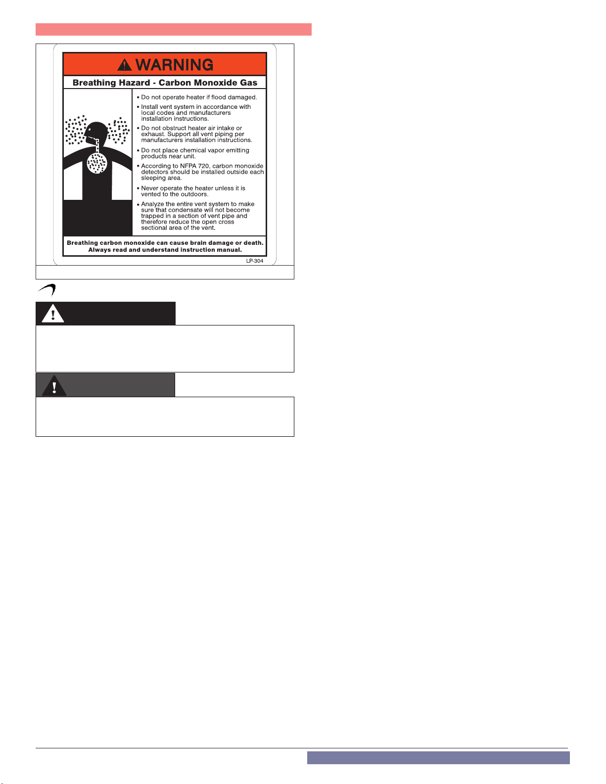
Part 3 - Prepare the Boiler for Installation
Figure 9 - CO Warning Label
J. Removing a Boiler from a Common Vent System
DANGER
Do not install the boiler into a common vent with any other appliance.
This will cause ue gas spillage or appliance malfunction, resulting
in possible substantial property damage, severe personal injury, or
death.
WARNING
Failure to follow all instructions can result in ue gas spillage and
carbon monoxide emissions, causing severe personal injury or
death.
When removing an existing boiler, follow the steps below.
1. Seal any unused openings in the common venting system.
2. Visually inspect the venting system for proper size and horizontal
pitch to determine if there is blockage, leakage, corrosion, or other
deficiencies that could cause an unsafe condition.
3. If practical, close all building doors, windows, and doors between
the space in which the boiler remains connected to the common
venting system and other spaces in the building. Turn on clothes
dryers and any appliances not connected to the common venting
system. Turn on any exhaust fans, such as range hoods and
bathroom exhausts, at maximum speed. Do not operate a summer
exhaust fan. Close all fireplace dampers.
4. Place in operation the appliance being inspected. Follow the
lighting instructions. Adjust the thermostat so the appliance will
operate continuously.
5. Test for spillage at the draft hood relief opening after 5 minutes of
main burner operation. Use the flame of a match or candle or smoke
from a cigarette.
6. After it has been determined that each appliance remaining
connected to the common venting system properly vents when
tested as outlined, return doors, windows, exhaust fans, fireplace
dampers, and any other gas burning appliances to their previous
condition of use.
7. Any improper operation of the common venting system should be
corrected to conform to the National Fuel Gas Code, ANSI Z223.1.
When resizing any portion of the common venting system, the
system should approach the minimum size as determined using the
appropriate tables in Appendix G of ANSI Z223.1.
18
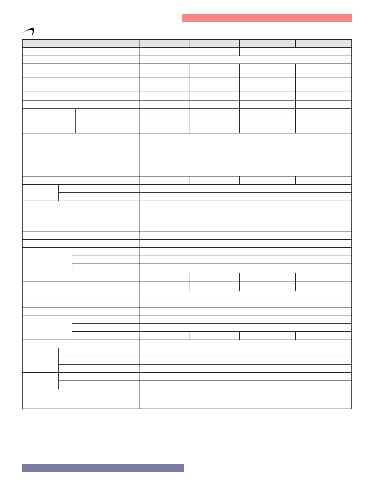
K. Technical Specifications
Model TRX085 TRX120 TRX110C TRX150C
Type Boiler Combi
Installation Indoor, Wall Hung, Fully Condensing
Minimum / Maximum Input (Btu/Hr)
Minimum / Maximum Input (Btu/Hr)
Hot Water Capacity
Minimum - Maximum Exhaust Vent Run
Minimum - Maximum Intake Air Pipe Run
Space Heating
Domestic Hot Water
DOE AFUE2 (%) 96 95 95.5 95
Heating Capacity
1, 2
(MBH) 79 111 98 111
35oF Rise N/A N/A 6.8 8.5
45oF Rise N/A N/A 5.3 6.6
77oF Rise N/A N/A 3.1 3.8
Flue System Category IV, Sealed Combustion Direct Vent, Power Vent
Part 3 - Prepare the Boiler for Installation
1
1
3
3
9,400 / 85,000 13,200 / 120,000 11,200 / 106,000 13,200 / 120,000
N/A N/A 11,200 / 114,000 13,200 / 150,000
2” (6 - 100 feet), 3” (6 - 150 feet)
2” (0 - 100 feet), 3” (0 - 150 feet)
Approved Exhaust Vent Materials
3
PVC, CPVC, PP, Stainless Steel
Shipping Weight (lbs) 78 84 83 84
Gas Supply
Pressure
NG 3.5” to 10.5” WC
LP 8” to 13” WC
Power Supply 120V, 60 Hz, less than 12A
General Operating Conditions
Ambient Temperature Range: 33 – 104oF (0.6 – 40oC)
Product Approvals and Requirements: ANSI Z21.13 / CSA 4.9
Ignition System Direct Electronic Spark Ignition / Flame Rectification
Burner System Premixed Fuel Modulation / Stainless Steel Burner
Gas Valve System Air Ratio Valve
W 16” 3/64
Dimensions
(in Inches)
H 43” 5/8
D 15” 1/8
Approx. Full Boiler Weight (lbs) 88.2 88.6 91 92.8
Boiler Water Content (Gallons) 1.1 1.2 1.1 1.2
Boiler Setpoint Temperature Range 68 – 113oF Low Temperature / 95 - 179oF High Temperature
DHW Indirect Setpoint Temperature Range 104 – 149oF
DHW Setpoint Range (Combi Models) 97 – 140oF
Heat Exchanger MAWP 55
Water Pressure (PSI)
Pressure Relief Valve 30
DHW Max Pressure N/A N/A 125 125
Control Panel / Main Controller AristonThermo LCD Display / AristonThermo GALEVO2 Control
CH Supply / Return 1” Male Sweat with Adapter
Connection
Sizes
DHW Inlet / Outlet 3/4” Male Sweat with Adapter
Gas Inlet 3/4” Male NPT
Materials
Cabinet Painted Steel and Plastic
Heat Exchanger SA-312 Type 304L Stainless Steel Water Tube
Flame Rectifier Probe, Temperature Limit Control (190oF), Water Pressure Switch (Min. 8 PSI), Freeze
Safety Devices
Protection, Blocked Condensate Pressure Switch, Condensate Trap, Flue Temperature High Limit Sensor
(210oF), Blocked Vent Pressure Switch
Table 7 - Technical Specifications
NOTES:
1
Listed Input and Output Ratings are at minimum vent lengths at an altitude of 0 - 2000 ft. Numbers will be lower with longer venting and/or
altitudes greater than 2000 ft.
2
Ratings based on standard test procedures prescribed by the US Department of Energy.
3
The TRX requires a special venting system. Use only the vent materials and methods detailed in these installation instructions.
19
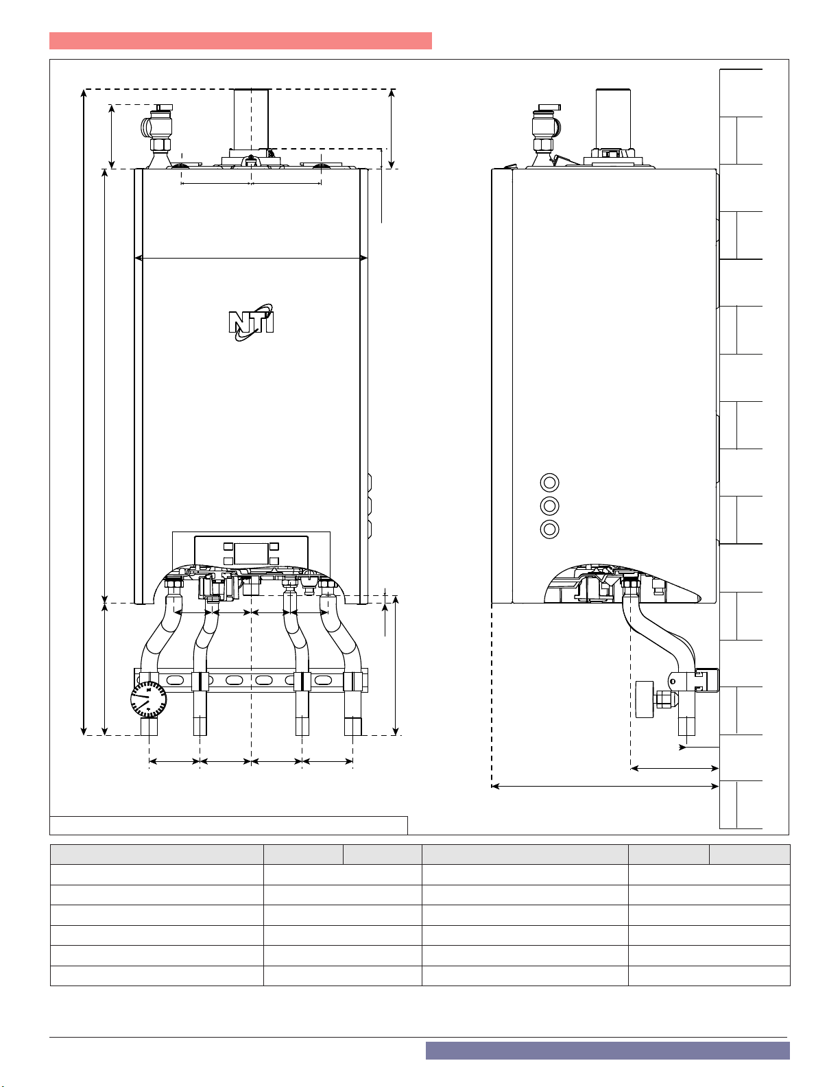
Part 3 - Prepare the Boiler for Installation
4-5/16”
(110 mm)
29-5/16”
(745 mm)
43-5/8”
(1108,15 mm)
(120 mm)
15-3/4”
(400 mm)
5-3/8”
(136,5 mm)
4-3/4”4-3/4”
(120 mm)
1-3/8”
(34,2 mm)
8-15/16”
(226,65 mm)
2-9/16”
(65mm) (67mm)
(67mm)
2-5/8”
2-9/16”2-5/8”
(65mm)
1/2”
13,1 mm
9-7/16”
(239,75 mm)
2-3/16”
3-7/16”
(87,2 mm)
(87,6 mm)
3-7/16”
(87,6 mm)
3-7/16”3-7/16”
(87,2 mm)
A B C D E
Figure 10 - Boiler Dimensions - NOTE: All Dimensions Are Approximate
15-5/16”
(390 mm)
(55,3mm)
5-7/8”
(150 mm)
Model TRX085 TRX120 Model TRX110C TRX150C
A - Central Heating Supply 1” A - Central Heating Supply 1”
B - Return from Indirect Water Heater 3/4” B - Domestic Hot Water Outlet 3/4”
C - Gas Inlet 3/4” C - Gas Inlet 3/4”
D - Domestic Hot Water Inlet Not Used D - Domestic Hot Water Inlet 3/4”
E - Central Heating Return 1” E - Central Heating Return 1”
F - Pressure Relief Valve F - Pressure Relief Valve
Table 8 - Boiler Adapter Dimensions
20
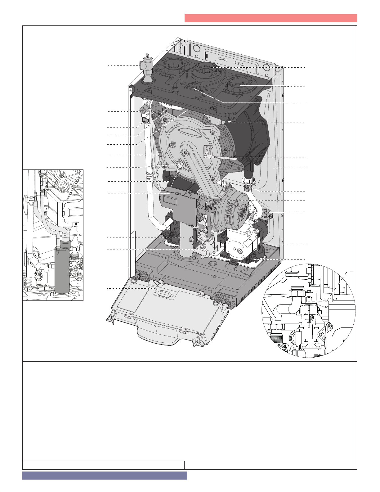
TRX085 - TRX120
Part 3 - Prepare the Boiler for Installation
11
1
2
3
4
5
6
7
8
9
11
12
25
24
23
22
21
20
19
18
17
15
14
26
13
1. Pressure relief valve
2. Air purge valve
3. Boiler outlet temperature sensor
4. Air pressure switch
5. Flue gas temperature sensor
6. Main heat exchanger
7. Flame detection electrode
8 Silencer
9. Junction box
11. Condensate trap
12. Gas valve
13. Control panel
14. CH circuit filter
Figure 11 - Boiler Component Locations and Descriptions
15. Circulation Pump with auto air vent
17. Water pressure switch
18. Modulating Fan
19. Boiler inlet temperature sensor
20. Frame
21. Ignition electrode
22. Spark generator
23. Combustion Analysis Test Point
24. Air intake connection
25. Exhaust vent connection
26. Diverter valve
21
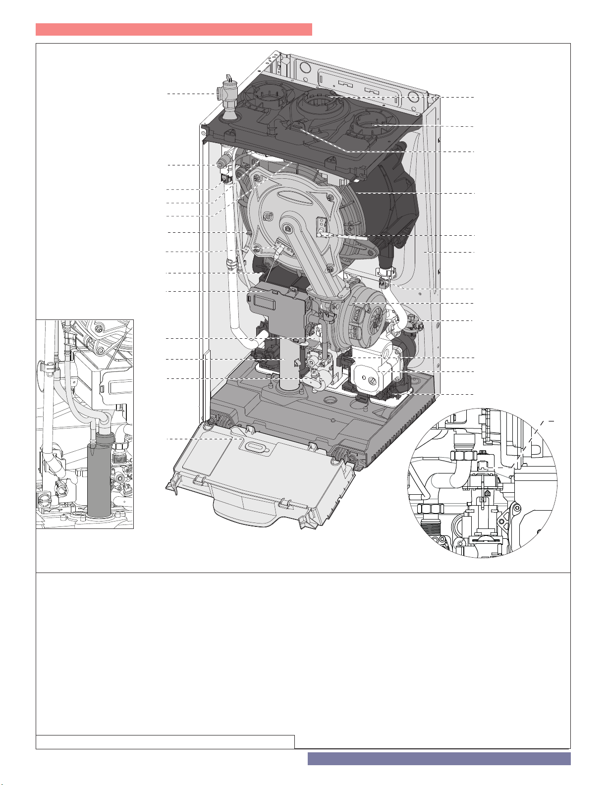
Part 3 - Prepare the Boiler for Installation
TRX110C - TRX150C
1
2
3
4
5
6
7
8
9
10
11
12
25
24
23
22
21
20
19
18
17
16
15
14
13
11
1. Pressure relief valve
2. Air purge valve
3. Boiler outlet temperature sensor
4. Air pressure switch
5. Flue gas temperature sensor
6. Main heat exchanger
7. Flame detection electrode
8 Silencer
9. Junction box
10. DHW heat exchanger
11. Condensate trap
12. Gas valve
13. Control panel
26
14. CH circuit filter
15. Circulation Pump with auto air vent
16. DHW Flow switch
17. Water pressure switch
18. Modulating Fan
19. Boiler inlet temperature sensor
20. Frame
21. Ignition electrode
22. Spark generator
23. Combustion Analysis Test Point
24. Air intake connection
25. Exhaust vent connection
26. Diverter valve
Figure 12 - Combi Boiler Component Locations and Descriptions
22
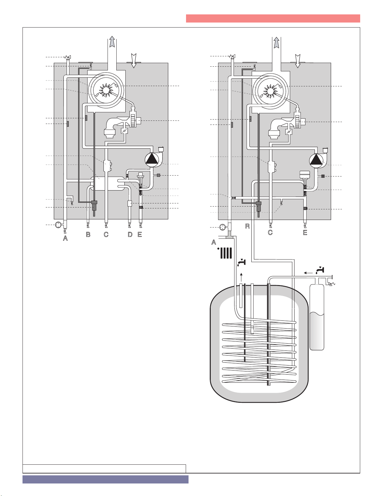
Part 3 - Prepare the Boiler for Installation
A
B C D E
14
16
26
27
17
15
28
11
10
12
18
214
1
psi
°F
2
7
6
19
3
29
A
C E
14
26
17
15
18
2
7
6
27
11
28
12
19
3
R
B
1
21
psi
°F
29
TRX110C - TRX150C
TRX085 - TRX120
1. Pressure relief valve
2. Air purge valve
3. Boiler outlet temperature sensor
4. Air pressure switch
5. Flue gas temperature sensor
6. Main heat exchanger
7. Flame detection electrode
8 Silencer
9. Junction box
10. DHW heat exchanger
11. Condensate trap
12. Gas valve
13. Control panel
14. CH circuit filter
15. Circulation Pump with auto air vent
16. DHW Flow switch
17. Water pressure switch
18. Modulating Fan
19. Boiler inlet temperature sensor
20. Frame
21. Ignition electrode
22. Spark generator
23. Combustion Analysis Test Point
24. Air intake connection
25. Exhaust vent connection
26. Diverter valve
27. By-pass
28. Drain valve
29. Pressure gauge
Figure 13 - Water Circuit Diagrams
23
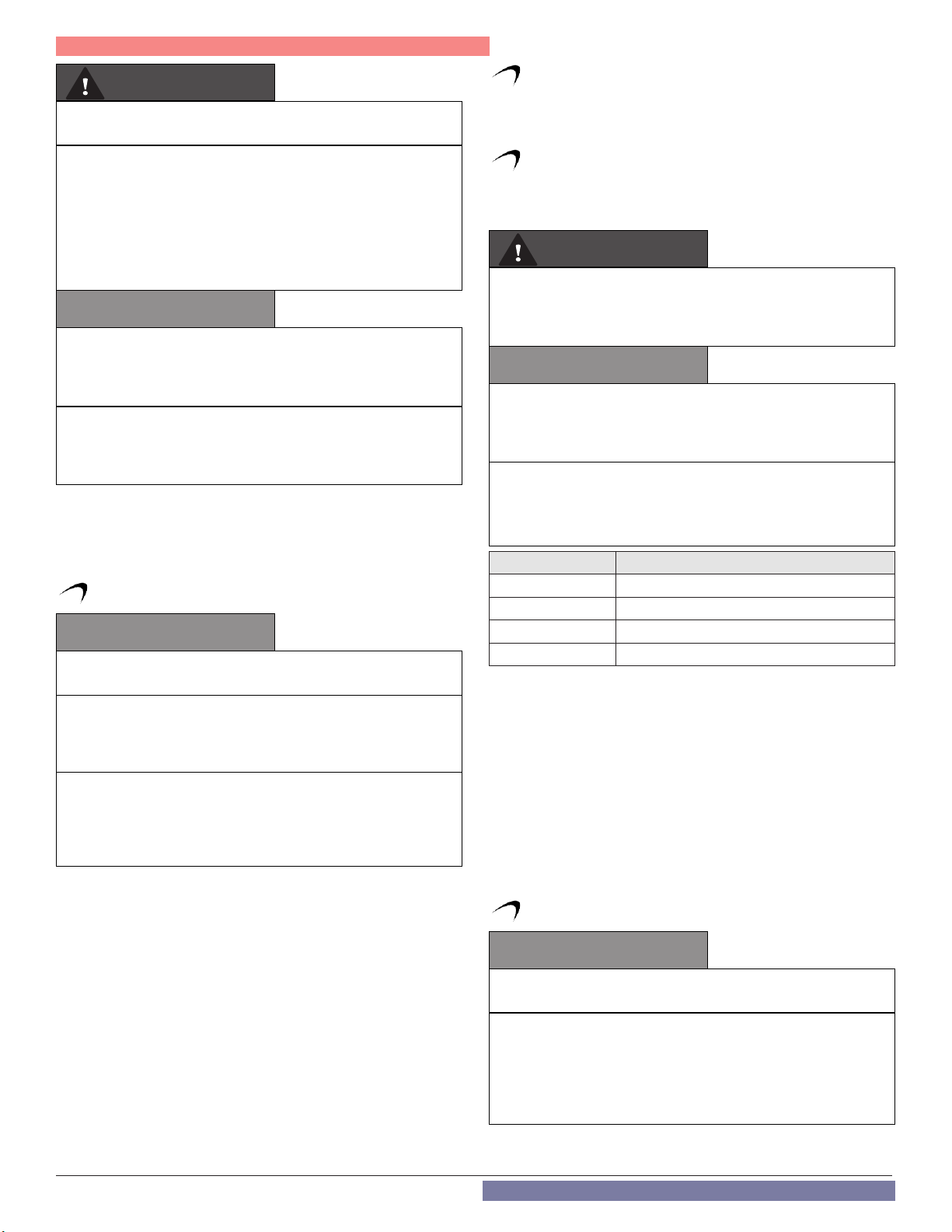
Part 4 - Water Piping
WARNING
Failure to follow the instructions in this section WILL VOID the warranty
and may result in property damage, severe personal injury, or death.
The National Standard Plumbing Code, the National Plumbing Code
of Canada, and the Uniform Plumbing Code limit heat transfer uid
pressure to less than the minimum working pressure of the potable
water system up to 30 PSI maximum. In addition, the heat transfer
uid must be water or another non-toxic uid having a toxicity of
Class 1, as listed in Clinical Toxicology of Commercial Products,
5th Edition. Failure to follow this warning could result in property
damage, severe personal injury, or death.
CAUTION
Do not apply a torch within 12” of the boiler. If sweat connections are
used, sweat tubing to the adapter before tting adapter to the water
connections on the boiler. Damages due to improper installation
practices ARE NOT covered by warranty.
Dielectric unions or galvanized steel ttings must not be used in a
system with this boiler. Doing so WILL VOID the warranty. Use only
copper, brass, or stainless steel ttings. Teon thread sealant must
be used on all connections.
Plumbing of this product should only be done by a qualified, licensed
plumber in accordance with all local plumbing codes. The boiler may
be connected to an indirect water heater to supply domestic hot water.
NTI offers indirect water heaters in a wide range of gallon sizes in either
stainless steel or glass-lined construction.
A. General Plumbing Information
CAUTION
The building piping system must meet or exceed the the piping
requirements in this manual.
Use two wrenches when tightening water piping at boiler. Use one
wrench to prevent the boiler return or supply line from turning.
Failure to prevent piping connections from turning could cause
damage to boiler components.
The boiler control module uses temperature sensors to provide
both high limit protection and modulating temperature control. The
control module may also provide low water protection by sensing
the water level in the heat exchanger. Some codes/jurisdictions may
require additional external controls.
The water connections must be installed in accordance with all local
and national plumbing codes, or any applicable standard with prevails.
• Pipe material must be suitable to meet local codes and industry
standards.
• The pipe must be cleaned and without blemish before any
connections are made.
• The size of the DHW pipes should be 3/4” diameter, and the CH
pipes should be 1” diameter.
• Isolation (shut-off valves) should be used on both the CH and DHW
loops to ease future servicing.
• All piping should be insulated.
It is recommended to install a sweat shut-off valve and a union in the
return and supply piping to ease future servicing. If there is a backflow
preventer or any type of a no return valve in the system, install an
additional tee here suitable for an expansion tank.
NOTE: The addition of a high temperature limiting device is important
if the boiler is to be connected to a domestic hot water system.
24
B. Backflow Preventer
Use a backflow preventer specifically designed for hydronic boiler
installations. This valve should be installed on the cold water fill supply
line per local codes.
C. Expansion Tank
Expansion Tank and Make-Up Water
1. Ensure that the expansion tank is designed and sized to correctly
handle boiler and system water volume and temperature.
WARNING
Expansion tanks must be sized according to total system volume. This
includes all length of pipe, all xtures, boilers, etc. Failure to properly
size for system expansion could result in wasted time, money, possible
property damage, serious personal injury, or death.
CAUTION
Undersized expansion tanks cause system water to be lost from the
relief valve, causing make-up water to be added. Eventual boiler
failure can result due to excessive make-up water addition. SUCH
FAILURE IS NOT COVERED BY WARRANTY.
DO NOT install automatic air vents on closed type expansion tank
systems. Air must remain in the system and return to the tank to
provide an air cushion. An automatic air vent would cause air to leave
the system, resulting in improper operation of the expansion tank.
Model Heat Exchanger Volume (Gallons)
TRX085 1.1
TRX120 1.2
TRX110C 1.1
TRX150C 1.2
Table 9 - Heat Exchanger Water Volume (To Aid in Expansion Tank Sizing)
2. The expansion tank must be located as shown in Applications, this
manual, or following recognized design methods. See expansion tank
manufacturer’s instructions for details.
3. Connect the expansion tank to the air separator only if the air
separator is on the suction side of the circulator. Always install the
system fill connection at the same point as the expansion tank
connection to the system.
4. Most chilled water systems are piped using a closed type expansion
tank.
DIAPHRAGM (OR BLADDER) EXPANSION TANK
Always install an automatic air vent on top of the air separator to
remove residual air from the system.
D. Piping the Boiler
CAUTION
Boiler Models should not be operated as a direct potable hot water
heater. Only Combi Models should be used to directly heat hot water.
Use at least the MINIMUM pipe size for all appliance loop piping.
This is to avoid the possibility of inadequate ow through the
appliance. Using less than the required minimum pipe size and
piping could result in system problems, property damage, and
premature appliance failure. Such problems ARE NOT covered by
product warranty.
NOTE: Observe the minimum 1” clearance around all uninsulated hot
water pipes when openings around pipes are not protected by noncombustible materials.
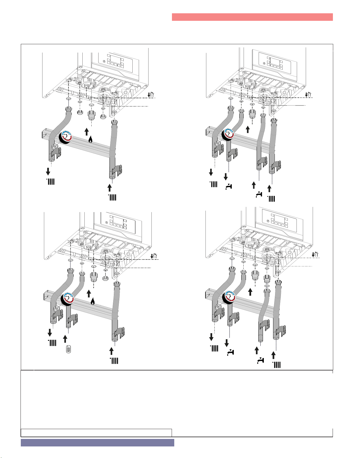
Part 4 - Water Piping
Connect the 3/4” DHW inlet and outlet pipes. A shut-off valve between the city water supply and DHW inlet is recommended for ease of service.
NTI offers threaded 3/4” DHW tankless isolation valves with a DHW pressure relief valve for ease of installation and future service.
Connect the 1” CH return and supply pipes. Isolation valves are recommended for ease of service.
TRX085 or TRX120 only Heating
40
20
60
psi
80
0
20
250
0
50 200
100 150
C
A
E
TRX085 or TRX120 with Indirect Water Heater
TRX110C
I
L
40
20
60
psi
80
A
0
0
20
50 200
100 150
B
250
C
D
E
I
L
TRX150C
40
20
60
psi
80
0
0
20
50 200
100 150
250
C
A
B
E
TRX085 - TRX120
A. CH Supply 1”
B. Return from Indirect Water Heater 3/4"
C. Gas Inlet 3/4"
D. Not Used
E. CH Return 1”
I. Drain Valve
L. Condensate Discharge
I
L
40
20
60
psi
80
0
0
20
50 200
250
100 150
C
I
L
A
B
D
E
TRX110C - TRX150C
A. CH Supply 1”
B. DHW Outlet 3/4"
C. Gas Inlet 3/4"
D. DHW Inlet 3/4"
E. CH Return 1”
I. Drain valve
L. Condensate discharge
Figure 14 - Water / Gas Connections
25
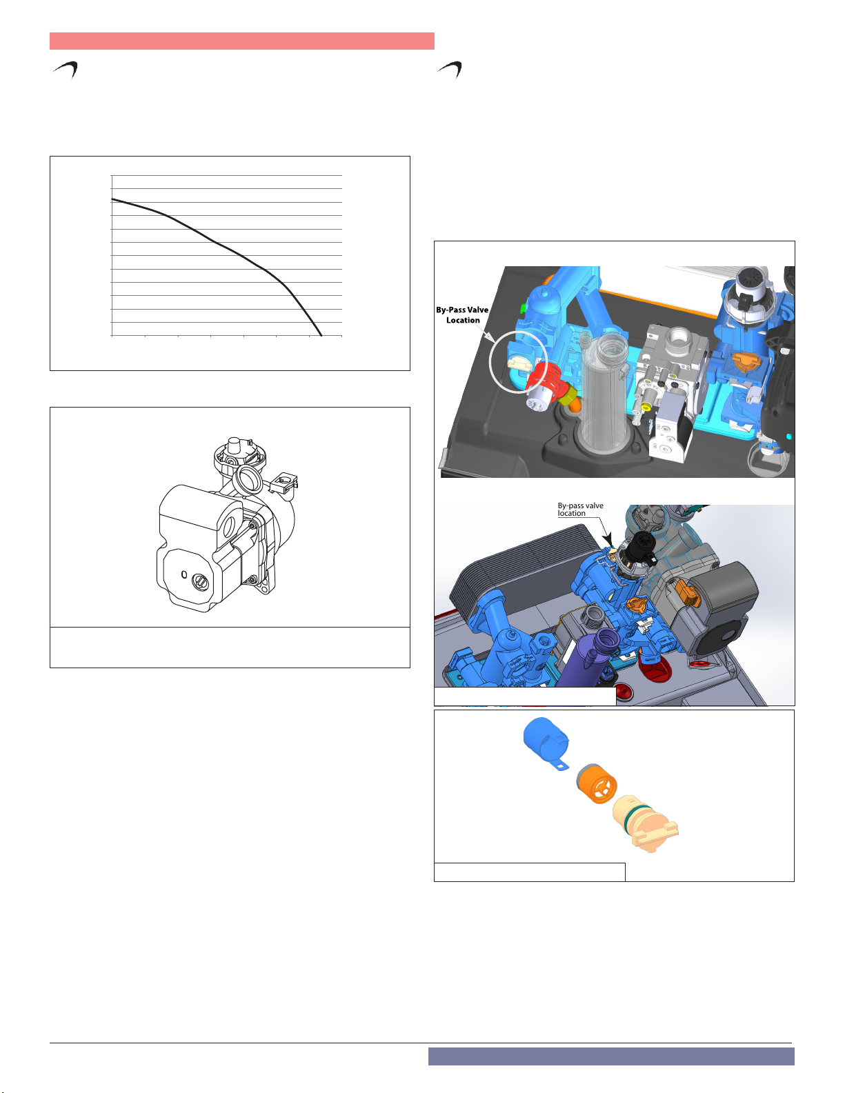
Part 4 - Water Piping
By-Pass Valve
Location
By-pass valve
location
E. Internal Circulation Pump
To calculate the size of the heating installation refer to the graph below.
Graph Representing the Available Circulation Pump Head
feet
24
20
16
12
8
4
0
0 1 2 3 4 5 6 7
gal/min
Table 10 - Internal Circulation Head Curve
F. By-Pass Valve
This boiler has a by-pass valve which requires no adjustment.
The by-pass valve protects the heat exchanger from overheating by
guaranteeing a minimum flow rate of 2 gpm within the primary heat
exchanger. This protects the primary heat exchanger from overheating
when water circulation is insufficient or heating system load is reduced
(ex: due to the response of thermostatic valves or zone valves).
The by-pass valve is located:
- in the left hydraulic block for TRX085 and TRX120.
- in the right hydraulic block , behind the three-way valve, for
TRX110C
TRX085 - TRX120
and
TRX150C.
Figure 15 - Internal Circulation Pump NOTE: Ensure the Air Vent on the
Internal Circulation Pump Remains Open after Installation
TRX110C - TRX150C
Figure 16 - By-Pass Valve Location
Figure 17 - By-Pass Valve Assembly
26
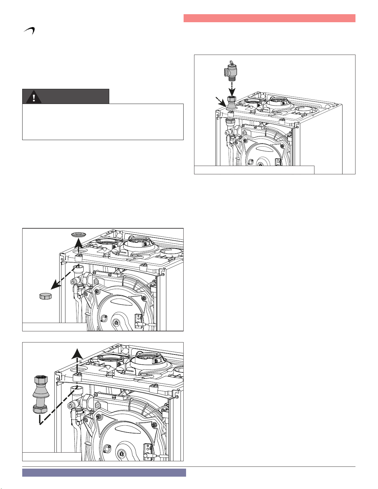
Part 4 - Water Piping
G. CH and DHW Pressure Relief Valves
An external pressure relief valve must be installed on this appliance for the
CH loop. When installing, observe the following guidelines.
This boiler has a high-temperature shut-off switch built in as a standard
safety feature. Therefore, a “pressure only” relief valve is required.
DO NOT operate this appliance before the supplied pressure relief
valve is installed with sufficient relieving capacity in accordance with
the ASME rating plate on the appliance.
WARNING
The pressure relief valve must be installed with the provided adaptor
pipe in the top of the boiler as detailed in Figure 19. No other valves
should be placed between the pressure relief valve and the appliance.
Failure to comply with these guidelines can result in substantial
property damage, personal injury, or death.
CH Loop
This boiler is provided with a CH pressure relief valve that complies with
the ANSI/ASME Boiler and Pressure Vessel Code, Section IV (Heating
Boilers). The included 30 psi CH Pressure Relief Valve must be installed
at the top of the boiler, using the included pipe adapter and grommet,
as illustrated below.
DO NOT install a relief valve with a pressure rating in excess of 50 psi
- the maximum allowable operating pressure of the boiler. The relief
valve capacity must exceed the BTU/H input capaciy of the boiler. To
install the pressure relief valve proceed as follows:
1. Remove the plastic cover on the top of the boiler.
2. Remove the nut on the flow pipe.
4. Connect the pressure relief valve and gasket.
NOTE: To maintain an airtight seal, ensure the gasket boot is
properly fitted into the top of the boiler cabinet.
Figure 20 - Connect CH Pressure Relief Valve
DHW Loop (Combi Models)
The DHW piping must be provided with a DHW pressure relief valve that
complies with local codes, but not less than valves certified as meeting
the requirements of Relief Valves for Hot Water Supply Systems, ANSI
Z21.22 / CSA4.4 by a nationally recognized lab that maintains periodic
inspection of production listed equipment.
A DHW pressure relief valve is not included with the boiler, and is to be
field supplied and installed in the DHW piping. DO NOT install a DHW
relief valve with a pressure rating greater than 125 psi - the maximum
allowable operating pressure of the boiler’s DHW circuit.
After installing the relief valves and filling and pressurizing the system,
test the operation of the valves by lifting the levers.
Make sure the valves discharge freely. If a valve fails to operate correctly,
replace it with a new relief valve.
The relief valve capacity must exceed the BTU/H input capacity of the
boiler.
Figure 18 - Remove the Caps
3. Insert the pipe and gasket.
Figure 19 - Insert the Pipe
Radiant heating
For appliances with underfloor heating, it is possible but not necessary
to fit a safety thermostat onto the radiant heating outlet.
If the thermostat cannot be installed, the radiant heating equipment
must be protected by a thermostatic valve, or by a by-pass to prevent
the floor from reaching too high a temperature.
27
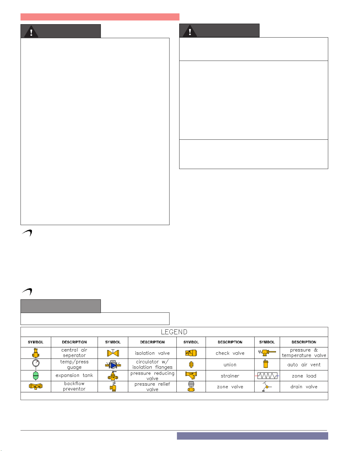
Part 4 - Water Piping
WARNING
To avoid water damage or scalding due to relief valve operation:
• Discharge line must be connected to relief valve outlet and run
to a safe place of disposal. Terminate the discharge line in a
manner that will prevent possibility of severe burns or property
damage should the relief valve discharge.
• Discharge line must be as short as possible and the same size
as the valve discharge connection throughout its entire length.
• Discharge line must pitch downward from the valve and
terminate at least 6” above the oor drain, making discharge
clearly visible.
• The discharge line shall terminate plain, not threaded, with a
material serviceable for temperatures of 375oF or greater.
• Do not pipe discharge to any location where freezing could
occur.
• No valve may be installed between the relief valve and boiler
or in the discharge line. Do not plug or place any obstruction in
the discharge line.
• Test the operation of the relief valve after lling and pressurizing
the system by lifting the lever. Make sure the valve discharges
freely. If the valve fails to operate correctly, immediately replace
with a new properly rated relief valve.
• Test relief valve at least once annually to ensure the waterway
is clear. If valve does not operate, turn the boiler “off” and call
a plumber immediately.
• Take care whenever operating relief valve to avoid scalding
injury or property damage.
FAILURE TO COMPLY WITH THE ABOVE GUIDELINES COULD
RESULT IN FAILURE OF RELIEF VALVE OPERATION, RESULTING
IN POSSIBILITY OF SUBSTANTIAL PROPERTY DAMAGE, SEVERE
PERSONAL INJURY, OR DEATH.
WARNING
Do not thread a cap or plug into the relief valve or relief valve line
under any circumstances! Explosion and property damage, serious
injury, or death may result.
RE-INSPECTION OF RELIEF VALVES: Relief valves should be
inspected AT LEAST ONCE EVERY THREE YEARS, and replaced
if necessary, by a licensed plumbing contractor or qualied service
technician to ensure that the product has not been affected by
corrosive water conditions and to ensure that the valve and discharge
line have not been altered or tampered with illegally. Certain naturally
occuring conditions may corrode the valve and its components over
time, rendering the valve inoperative. Such conditions can only be
detected if the valve and its components are physically removed and
inspected. Do not attempt to conduct an inspection on your
own. Contact your plumbing contractor for a re-inspection to assure
continued safety.
FAILURE TO RE-INSPECT THE RELIEF VALVE AS DIRECTED
COULD RESULT IN UNSAFE TEMPERATURE AND/OR
PRESSURE BUILD-UP WHICH CAN RESULT IN PROPERTY
DAMAGE, SERIOUS PERSONAL INJURY, OR DEATH.
H. Air Elimination Device
A micro bubble air elimination device must be installed in every boiler
installation. Automatic air vents alone are not an acceptable substitute
for a micro bubble air elimination device. Here are a few examples of
acceptable devices.
• Spirovent
• TACO 4900 Series
• Caleffi Discal
I. Applications*
CAUTION
Mixing valves are required for the protection of low temperature loops.
Figure 21 - Piping Symbol Legend
28
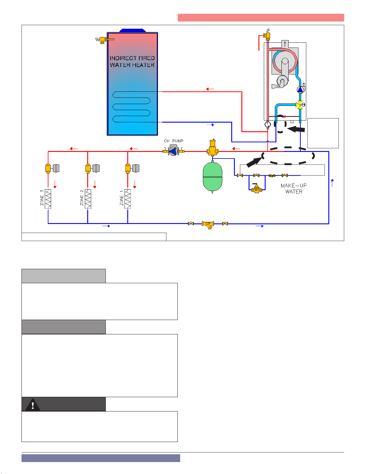
Part 4 - Water Piping
Primary/Secondary Piping Shown
Cap this
fitting
when not in
use
Figure 22 - TRX085 / TRX120 with Single Central Heating Circulator
NOTE: In piping applications utilizing a single zone, it is recommended
that the installer use flow / check valves with weighted seats at or near
the appliance to prevent gravity circulation.
NOTICE
Figure illustrates the basic plumbing requirements for a TRX085 /
TRX120 boiler installation utilizing Primary/Secondary piping when
the boiler circulator will not provide adequate ow for the system.
Primary / Secondary is required to provide adequate ow for the
secondary circuits.
CAUTION
On TRX085 / TRX120 Models Only.
If the boiler to be used only in Heating Mode (not connected to
an indirect water heater), cap the fitting as indicated in the figure
above and the electrical connection of the 3-way valve motor
MUST BE DISCONNECTED while the boiler is operating in central
heating mode. This will lock the valve motor in central heating
mode and ensure freeze protection operates properly. Failure to
disconnect the valve may disable boiler freeze protection and
result in property damage.
WARNING
The piping will not support the weight of the circulators. Refer to
the circulator manufacturer’s instructions to properly support the
circulator. Failure to comply with these instructions could result in
property damage, severe personal injury, or death.
NOTES:
1. This drawing is meant to show system piping concept only.
Installer is responsible for all equipment and detailing required by
local codes.
2. All closely spaced tees shall be within 4 pipe diameters center to
center spacing.
3. A minimum of 6 pipe diameters of straight pipe shall be installed
upstream and downstream of all closely spaced tees.
4. The minimum pipe size of DHW piping should be ¾” diameter and
CH piping should be 1” in diameter.
5. Circulators are shown with isolation flanges. The alternative is
standard flanges with full port ball valves. Purge valves can be used
with circulator flanges as an alternative.
6. Piping shown is Primary/Secondary.
7. Install a minimum of 12 diameters of straight pipe upstream of all
circulators.
8. VERY IMPORTANT – Minimum flow rates outlined in this manual
(2 gpm) must be maintained through the heat exchanger to
minimize short cycling.
9. In a valve-based system, each heating zone has a zone valve which
opens when that zone calls for heat. Each zone thermostat is
wired to its corresponding zone valve. Contacts in the zone valves
provide a signal to the boiler to operate when there is a call for
heat.
10. Unit is equipped with built-in primary pump. This pump is sized
to ensure proper flow rate through the boiler heat exchanger and
related piping.
11. IWH Applications - a mixing valve is recommended if the DHW
temperature is set above the factory setting of 119oF.
29
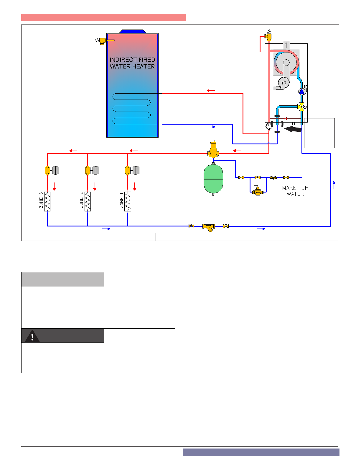
Part 4 - Water Piping
Cap this
fitting
when not in
use
Figure 23 - TRX085 / TRX120 without Central Heating Circulator
NOTE: In piping applications utilizing a single zone, it is recommended
that the installer use flow / check valves with weighted seats at or near
the appliance to prevent gravity circulation.
NOTICE
Figure illustrates the basic plumbing requirements for a TRX085
/ TRX120 boiler installation without an external Central Heating
circulator; the boiler’s internal circulator delivers ow to the heating
system. Application is limited to zone valve (or non-circulator)
distribution systems with small ow requirements (e.g. systems
requiring no more than 5 gpm at 9 ft. of head pressure)
WARNING
The piping will not support the weight of the circulators. Refer to
the circulator manufacturer’s instructions to properly support the
circulator. Failure to comply with these instructions could result in
property damage, severe personal injury, or death.
NOTES:
1. This drawing is meant to show system piping concept only.
Installer is responsible for all equipment and detailing required by
local codes.
2. The minimum pipe size of DHW piping should be ¾” diameter and
CH piping should be 1” in diameter.
3. Circulators are shown with isolation flanges. The alternative is
standard flanges with full port ball valves. Purge valves can be used
with circulator flanges as an alternative.
4. Install a minimum of 12 diameters of straight pipe upstream of all
circulators.
5. VERY IMPORTANT – Minimum flow rates outlined in this manual
(2 gpm) must be maintained through the heat exchanger to
minimize short cycling.
6. In a valve-based system, each heating zone has a zone valve which
opens when that zone calls for heat. Each zone thermostat is
wired to its corresponding zone valve. Contacts in the zone valves
provide a signal to the boiler to operate when there is a call for
heat.
7. Unit is equipped with built-in primary pump for the heating
loop. This pump is sized to ensure proper flow rate through the
boiler heat exchanger and related piping.
8. IWH Applications - a mixing valve is recommended if the DHW
temperature is set above the factory setting of 119oF.
9. In direct (not primary / secondary) piping applications, it is
required to increase fill pressure to 20 psi to ensure proper system
operation.
30
 Loading...