

Page 1

User’s
Information
TRX
TRX
Manual
User Operating
Instructions
NOTICE
The manufacturer reserves the right
to make product changes or updates
without notice and will not be held
liable for typographical errors in
literature.
The surfaces of these products
contacted by potable (consumable)
water contain less than 0.25% lead by
weight as required by the Safe Drinking
Water Act, Section 1417.
Residential Condensing Gas Boiler
NOTE TO CONSUMER:
PLEASE KEEP ALL INSTRUCTIONS
FOR FUTURE REFERENCE.
Heat Exchanger Bears the ASME “H” Stamp
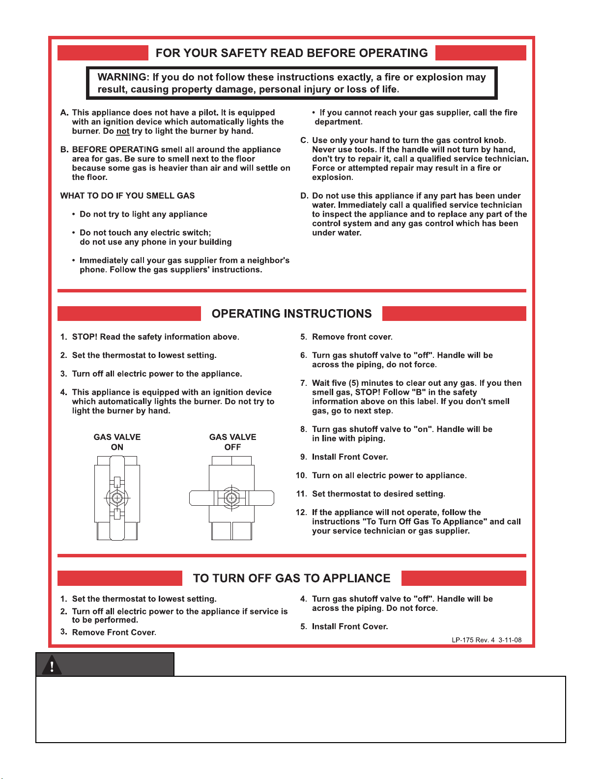
WARNING
IF THE INFORMATION IN THIS MANUAL IS NOT FOLLOWED EXACTLY,
A FIRE OR EXPLOSION MAY RESULT, CAUSING PROPERTY DAMAGE,
PERSONAL INJURY, OR LOSS OF LIFE. DO NOT STORE GASOLINE OR
OTHER FLAMMABLE VAPORS AND LIQUIDS IN THE VICINITY OF THIS OR
ANY OTHER BOILER.
WHAT TO DO IF YOU SMELL GAS
• Do not try to light any boiler.
• Do not touch any electrical switch.
• Do not use any phone in your building.
• Immediately call your gas supplier from a neighbor’s phone. Follow the
gas supplier’s instructions.
• If you cannot reach your gas supplier, call the fire depar tment.
Installation and service must be provided by a qualified installer,
service agency, or the gas supplier.
Improper installation, adjustment, alteration, service, or maintenance could
void product warranty and cause property damage, severe personal injury,
or death.
California Proposition 65 Warning: This product contains chemicals
known to the State of California to cause cancer, birth defects, or other
reproductive harm.
Page 2
WARNING
The combustion chamber insulation in this product contains ceramic fiber material. Ceramic fibers can be converted to cristobalite
in very high temperature applications. The International Agency for Research on Cancer (IARC) has concluded, “Crystalline silica
inhaled in the form of quartz or cristobalite from occupational sources is carcinogenic to humans (Group 1).” DO NOT, UNDER ANY
CIRCUMSTANCES, OPEN THE COMBUSTION CHAMBER OF THIS BOILER! The combustion chamber of this boiler may be opened by a
qualified service technician ONLY. FAILURE TO FOLLOW THESE INSTRUCTIONS CAN RESULT IN SUBSTANTIAL PROPERTY DAMAGE,
SEVERE PERSONAL INJURY, OR DEATH.
Page 3
SPECIAL ATTENTION BOXES
The following defined terms are used throughout this
manual to bring attention to the presence of hazards of
various risk levels or to important product information.
DANGER
DANGER indicates an imminently hazardous situation
which, if not avoided, will result in serious personal injury
or death.
WARNING
WARNING indicates a potentially hazardous situation
which, if not avoided, could result in personal injury or death.
CAUTION
CAUTION indicates a potentially hazardous situation which,
if not avoided, may result in moderate or minor personal
injury.
CAUTION
CAUTION used without the safety alert symbol indicates a
potentially hazardous situation which, if not avoided, may
result in property damage.
NOTICE
NOTICE is used to address practices not related to personal
injury.
Table of Contents
Part 1 - Product and Safety Information 4
A. Before Operating the Boiler 4
B. Primary Water 5
C. Freeze Protection 5
D. Combustion Air Contamination Prevention 5
Part 2 - Operating Instructions 6
A. Boiler Operation 7
B. Ignition Procedure 7
C. Central Heating (CH) Temperature Adjustment 7
D. Domestic Hot Water (DHW) Temperature Adjustment 7
E. During Operation 8
F. User Menu 8
G. INFO Menu 10
H. Date and Time 11
I. Automatic CH Temperature Control (AUTO) 11
J. Outdoor Heating Curve Slope 11
K. Outdoor Heating Curve Parallel Shift 11
L. Room temperature Day/night 12
M. Time programs - heating schedule 12
N. Automatic summer / winter changeover 12
O. During operation 13
P. General Cautionary Statements 13
Part 3 - Maintenance Schedule 14
A. Owner Maintenance 14
B. Qualified Service Technician 14
Part 4 - Maintenance Procedures 15
A. Daily Maintenance - To Be Performed by Owner 15
B. Monthly Maintenance - To Be Performed by Owner 15
C. 6 Month Maintenance - To Be Performed by Owner 16
D. Annual Maintenance - To Only Be Performed by a Qualified
Service Technician 16
Part 5 - Troubleshooting for the User 17
Maintenance Notes 18
3
Page 4
Part 1 - Product and Safety Information
WARNING
Proper care of this boiler is the user’s / owner’s responsibility.
The user should carefully read and understand the Operating
Information in this manual before operating this boiler.
User - Have this boiler serviced / inspected annually by a
qualied service technician.
FAILURE TO ADHERE TO THE GUIDELINES AND WARNINGS
IN THIS MANUAL CAN RESULT IN SUBSTANTIAL PROPERTY
DAMAGE, SEVERE PERSONAL INJURY, OR DEATH.
DO NOT use this boiler if ANY part has been under water.
Immediately call a qualied technician to inspect the boiler and
replace any part of the control system or gas control which has
been under water.
DO NOT power up the boiler unless the gas and water supply
valves are fully opened. Make sure the fresh air intake pipe and
exhaust vents are open and functional.
DO NOT attempt to install, repair, or service this boiler. Contact
a qualied technician if the boiler needs repair or maintenance.
Ask your gas supplier for a list of qualied service providers.
DO NOT attempt to disassemble this boiler. If repairs are required,
contact a qualied service technician.
All safety devices must be tested by the installer / qualied
service technician after the boiler is installed.
Always verify proper boiler operation with the qualied service
technician after servicing.
The gas ignition system components must be protected from
water (dripping, spraying, rain, etc.) during boiler operation
and service (circulator replacement, condensate trap, control
replacement, etc.)
DO NOT touch the exhaust vent or hot water pipes during boiler
operation.
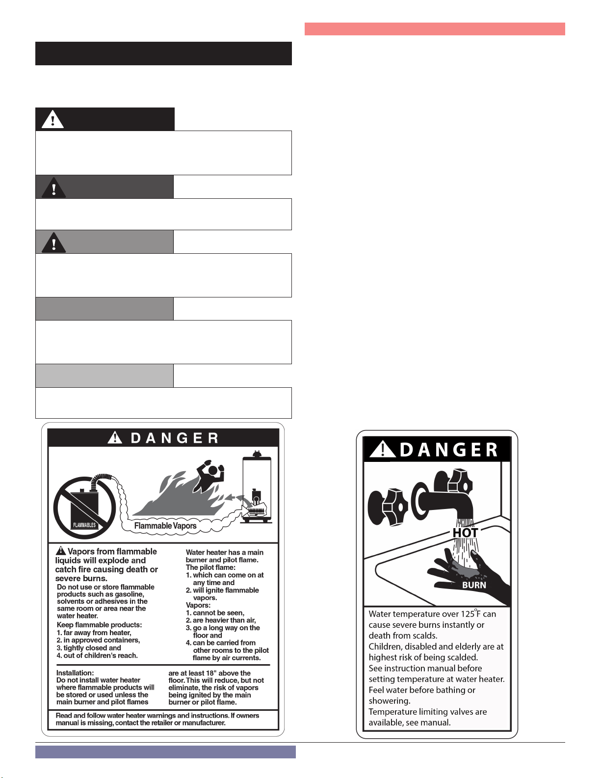
Combi models / boilers using indirect water heating: Always be
careful when opening a hot water faucet or draining water from
the boiler. Water temperature over 125°F can instantly cause
severe burns or death from scalds. Children, disabled, and
elderly are at the highest risk of being scalded. See Installation
Manual before setting temperature at boiler. Feel water before
bathing or showering!
A. Before Operating the Boiler
1. Check the Gas Type
When operating the boiler for the first time, ensure the connected
gas type matches the boiler gas type. NTI boilers are factory set
to operate on Natural Gas. BEFORE OPERATING WITH PROPANE
the boiler must be converted to Propane operation by a qualified
service technician, using the conversion kit specific to the boiler
model.
DANGER
Attempting to operate this boiler on Propane when it has not been
correctly converted to Propane operation will result in improper
boiler operation resulting in property damage, personal injury, or
death.
2. Check the Power (120V / 60 Hz)
Ensure the boiler is connected to a properly rated power supply.
WARNING
Failure to connect the boiler to the properly rated power supply
described above (120V / 60Hz) could result in property damage,
personal injury, or death.
3. Check the Automatic Feed Valve
Ensure the automatic feed valve to the boiler is providing the
proper pressure to the central heating (CH) loop.
4. Check the Gas Shut-Off Valve
Ensure the manual gas shut-off valve is open. The boiler will not
operate unless it is supplied with gas.
WARNING
It is the user’s responsibility to know the location of the gas shut-off
valve and how to operate it. Immediately close the gas shut-off valve
if the boiler is subjected to fire, overheating, flood, physical damage,
or any other damaging condition that might affect the operation of
the unit. Have the boiler checked by a qualified technician before
resuming operation.
Call a qualified service technician if repair of the gas pipeline or
replacement of the gas regulator is necessary.
5. Check the area around the boiler.
Remove any combustible or flammable materials from the area
around the boiler and do not hang anything from the exhaust
vent pipe.
This boiler features a factory installed overheating prevention
device. This limit will shut down the boiler in the event that
the boiler water temperature exceeds the set point of the limit
control. Certain local codes require additional water temperature
limiting devices.
4
WARNING
DO NOT store flammable or combustible materials near this boiler.
DO NOT use spray paint, hair spray, or any other flammable sprays
near the boiler or near the exterior fresh air intake pipe termination.
DO NOT place any items in or around the exterior exhaust vent
termination and/or fresh air intake pipe that could restrict or block
the flow in or out of the vent system.
Exhaust gas entering the living space can cause carbon monoxide
poisoning. If exhaust gas should leak into the living space:
• Shut down the boiler.
• Close the gas valve.
• Open windows for ventilation.
Immediately call a qualified service technician to inspect the boiler
and exhaust vent pipe. Any damages to the exhaust vent pipe should
be repaired immediately.
Page 5
Part 1 - Product and Safety Information
B. Primary Water
• Do not attempt to clean the heating system. Call a qualified
service technician for service.
• If you notice any leaks, immediately call a qualified service
technician. Leaks in boiler or piping must be repaired at once.
C. Freeze Protection
WARNING
Closed loops that use glycol as heat transfer fluid must be serviced
periodically. Glycol can break down over time, become acidic, and
attack gaskets and seals in boilers. This can result in property damage,
severe personal injury, or death.
Each glycol manufacturer has different recommendations for
testing and replacement. Do not test glycol quality yourself. Have
your qualified service technician check glycol quality during annual
servicing. If you are unsure when your glycol was last tested, call a
qualified service technician to test and replace glycol, if necessary.
DO NOT shut off the boiler for long periods of time during potentially
freezing conditions. If the boiler must be shut off during potentially
freezing conditions (is not to be used for an extended period of time),
shut down the system and drain it of water. Shut off the gas and cold
water supply valves.
Ensure exposed water pipes are thermally insulated to prevent
damage due to freezing conditions. If the boiler is not to be used for
an extended period of time during freezing conditions, shut down
the system and completely drain the boiler.
If the water pipes should freeze, thaw the pipes with a hair dryer or
other electric heating device. If this does not work, call a qualified
service technician.
Products to Avoid
Spray cans containing
fluorocarbons
Permanent wave solutions Swimming pools
Chlorinated waxes / cleaners Metal fabrication plants
Chlorine-based swimming pool
chemicals
Calcium chloride used for thawing Refrigeration repair shops
Sodium chloride used for water
softening
Refrigerant leaks Auto body shops
Paint or varnish removers Plastic manufacturing plants
Hydrochloric or Muriatic acid
Cements and glues New building construction
Antistatic fabric softeners used in
clothes dryers
Chlorine-type bleaches, laundry
detergents, and cleaning solvents
Adhesives used to fasten building
products
Table 1 - Products and Areas Likely to Have Contaminants
NOTE: DAMAGE TO THE Boiler CAUSED BY EXPOSURE TO
CORROSIVE VAPORS IS NOT COVERED BY WARRANTY.
(Refer to the limited warranty for complete terms and conditions.)
Areas Likely to Have
Contaminants
Dry cleaning / laundry areas
and establishments
Beauty shops
Photo processing plants
Furniture refinishing areas
and establishments
Remodeling areas
Garages and workshops
D. Combustion Air Contamination Prevention
DANGER
Do not operate the boiler if its combustion air intake is located in or
near one of the areas or in the vicinity of products listed in Table 1.
These areas will always contain hazardous contaminants that can
form strong acids while passing through the burner and vent
system. These acids will corrode the boiler’s heat exchanger, burner
components and vent system, resulting in flue gas spillage and/
or water leakage, possible substantial property damage, severe
personal injury, or death. If the boiler combustion air intake is located
in any area likely to cause or contain contamination, or if products
which would contaminate the air cannot be removed, the intake
must be re-piped and terminated to another location.
DO NOT re-pipe ventilation system on your own. Call a qualified
service provider for assistance.
5
Page 6
Part 2 - Operating Instructions
AUTO
0
ON OFF
COMFORT
MENU PAR
CODE
SRA
21 3 4 5 6
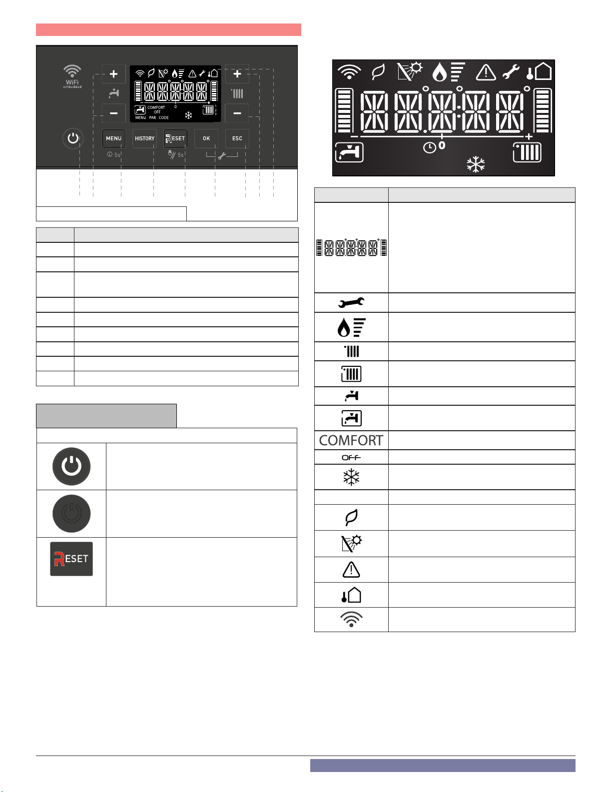
Figure 1 - Control and Display Overview
Item # Description
1 ON / OFF Button (see NOTICE below)
2 Domestic Hot Water Adjustment Button +/-
3
4 HISTORY Button - view last 10 errors
5 RESET Button (see NOTICE below)
6 OK – confirms menu selection
7 ESC – exits menu selection
8 Heating Temperature Adjustment Button +/-
9 Display
Table 2 - Control Descriptions
(short press = User Menu); (long press = Info Menu)
MENU
NOTICE
Operating Description
On / Off Button
The button lights (white) when the boiler is
electrically powered.
8 9
7
Display Icon Description
Digits Indicating:
• Boiler Status
• Temperature indication (oF) with bar
level
• Error Codes (ERROR)
• Press Reset Button Request (RESET)
(boiler lockout)
• Menu Settings
Technical assistance request
Flame detected with indication of power used
CH Heating Operation Set
CH Heating Operation Active
DHW Operation Set
DHW Operation Active
Hot Water Comfort Activated (Combi Only)
Boiler off with Antifreeze Function Active
Antifreeze Function Active
6
On / Off Button
The button is not lit in the event of an error or
power failure.
RESET BUTTON
The button lights (red) in the event of a lockout
error.
After pressing the Reset button to clear an
error condition, the button will flash for five (5)
seconds.
AUTO Automatic Temperature Control activated
High Efficiency Operation
(Low CH flow temperature)
Solar inlet temperature probe connected Optional
Error signal - Display will also show a code and
description
Outdoor Sensor Connected - Optional
WiFi Active
Table 3 - Display Icon Descriptions
Page 7

A. Boiler Operation
• Do not block flow of the boiler exhaust vent or intake pipe.
• Should overheating occur or gas supply fail to shut off, do not turn
off or disconnect electrical supply to the circulator. Instead, shut
off the gas supply at a location external to the boiler following the
instructions on page 2.
• Do not use this boiler if any part has been under water. Immediately
call a qualified service technician to inspect the boiler and replace
any part of the control system or gas control that has been under
water.
Part 2 - Operating Instructions
Operating Mode
Stand-by
CH request
supply temperature displayed
WARNING
OPERATING INSTRUCTIONS
1. STOP! DO NOT use this boiler unless it is completely lled with
water.
2. Ensure electrical power to the boiler is powered OFF.
3. This boiler is equipped with an ignition device which
automatically lights the burner. DO NOT attempt to light the
burner by hand.
4. Turn the gas shut-off valve clockwise to the “OFF” position. Do
not force.
5. Wait ve (5) minutes to clear out any gas. If you smell gas,
STOP! Follow the information on page 2, this manual. If you
don’t smell gas, go to the next step.
6. Turn manual gas shut-off valve to the “ON” position.
7. Turn ON electrical power to the boiler.
8. Generate a call for hot water by opening a hot water faucet in
the system.
9. If the boiler will not operate, follow the instructions on page 2
to turn off the gas to the boiler. Then call your qualied service
technician or gas supplier.
B. Ignition Procedure
Press the ON/OFF button on the control panel to switch on the
boiler. The display shows:
DHW request
DHW setpoint displayed
The ignition of the burner is indicated on the display by the symbol
. The dashes underneath indicate power level.
C. Central Heating (CH) Temperature Adjustment
It is possible to set the central heating (CH) temperature by pressing
the buttons described in Figure 1, Item 8.
The CH temperature range is 68 - 113oF (low temperature) and 95 179oF (high temperature).
Figure 3 - Central Heating (CH) Temperature Adjustment
NOTE: The CH Setpoint cannot be changed by pressing the buttons
item 8 (Figure 1) if an outdoor sensor is connected to the appliance.
When using an outdoor sensor, the appliance will automatically
change the CH target temperature based on the outdoor reset curve.
Figure 2 - Turn On the Boiler
D.
Domestic Hot Water (DHW) Temperature Adjustment
Not for non-COMBI using Aquastat
It is possible to set the domestic hot water (DHW) temperature by
pressing the buttons described in Figure 1, Item 2.
The DHW temperature range is 97 - 140oF. The previously set value will
flash on the display.
Figure 4 - Domestic Hot Water (DHW) Temperature Adjustment
7
Page 8

Part 2 - Operating Instructions
DANGER
Hotter water increases the risk of scald injury. Scalding may occur
within five (5) seconds at a setting of 140oF. Water temperature over
125oF can instantly cause severe burns or death from scalds. Children,
disabled, and elderly persons are at the highest risk of being scalded.
See instruction manual before setting temperature at the appliance.
Feel water before bathing or showering.
WARNING
An ASSE 1017 or ASSE 1070 temperature limiting or mixing valve is
recommended in installations servicing disabled or elderly persons,
or children. Mixing valves do not eliminate the risk of scalding.
To avoid scalding:
• Set the water heater set point temperature as low as possible.
• Feel water before bathing or showering.
• If thermostatic valves are required, use devices specifically
designed for such purpose. Install these devices in accordance
with instructions provided by the manufacturer.
Failure to install a temperature limiting or mixing valve and follow
these instructions could result in property damage, severe personal
injury, or death due to scalds.
E. During Operation
1. Check for Gas Leaks
Frequently check the gas pipe and connections for leaks with a
soapy solution. Gas is leaking if air bubbles appear during the test.
Close the gas supply valve and call your gas supplier for inspection.
WARNING
After any repair of the gas pipeline or replacement of the gas
regulator, call a qualified service technician to observe the installation
and replacement before restoring power to the boiler. Failure to do
so could result in a fire or explosion, substantial property damage,
severe personal injury, or death.
2. Check Exhaust Vent and Intake Pipe for Proper Ventilation
Ensure there is sufficient ventilation while operating the boiler.
Improper ventilation could result in premature boiler failure. Such
failures ARE NOT covered by boiler warranty.
3. Burn Warning
Take caution when inspecting the boiler and its internal
components, exhaust vent, and/or water pipes. These components
can get extremely hot during operation.
WARNING
Storing flammable or combustible materials near this boiler could
result in a fire or explosion, substantial property damage, severe
personal injury, or death.
4. Combustibles and Flammable Material Warning
Do not store combustibles or flammable materials in the vicinity of
this boiler. Do not hang anything from the exhaust pipe.
5. Check for Water Leaks
• Do not attempt to clean the heating system. Call a qualified
service technician for service.
• Immediately call a qualified service technician if you notice any
leaks. Leaks in boiler or piping must be repaired at once.
Exhaust gas entering the living space can cause carbon monoxide
poisoning. If exhaust gas should leak into the living space:
• Shut down the boiler.
• Close the gas valve.
• Open windows for ventilation.
• Ensure the CO detectors are operating properly.
Immediately call a qualied service technician to inspect the boiler
and exhaust vent pipe. Any damages to the exhaust vent pipe should
be repaired immediately. Failure to do so could result in a re or
explosion, substantial property damage, severe personal injury, or
death.
8
WARNING WARNING
DO NOT use this boiler for any purposes other than those specifically
described by NTI (to provide central heating and domestic hot water).
Using this boiler for unapproved purposes WILL VOID the warranty,
and could result in substantial property damage, serious personal
injury, or death.
Page 9

F. User Menu
Press the MENU button to open the user
menu.
To navigate within the menu or parameters,
press the + and - buttons (
To change a parameter, select it by pressing
the OK button.
To change the set value, press the + and -
buttons (
or )
Press the OK button to save.
To exit or save the changes, press the ESC
button.
Figure 5 - Access user menu
For parameters 5 to 12 it is also possible
to set / change the heating zone 2 (if
available).
By pressing the HISTORY button after
accessing the parameter, the number 1 or
2 of the selected zone appears next to the
heating symbol: / .
Continue to change the setting as
described above.
or )
.
.
Part 2 - Operating Instructions
Activate change with OK button, + / - buttons change the value, OK button for confirmation,
ESC to return without change.
1. NTI Wi-Fi
WIFI ON/OFF Wi-Fi
AP Access point open for 10 minutes
SN Shows Wi-Fi serial number (Not Appliance)
RESET Delete Wi-Fi settings Disconnect user account
ITEMP
2. Date and Time
The following values are displayed in a sequence. For setting, select OK and +/-.
Day (1-31)
Month (1-12)
Year (year)
Time (hh: mm) (*)
5.
Automatic C.H. temperature control / AUTO function
OFF AUTO function deactivated
ON AUTO function Active (AUTO appears on the display)
6.
Room temperature Day /
only applicable if using NTI room sensor(s)
7.
Room temperature Night /
only applicable if using NTI room sensor(s)
8.
Time programs – heating schedule /
only applicable if using NTI room sensor(s)
0+24 h
P1
P2
P3
06-22 h
P EXT Time program defined by REMOCON room unit or NTI NET app.
9.
Outdoor Heating Curve Slope (only with AUTO function active) /
10.
Outdoor Heating Curve Parallel Shift (only with AUTO function active) /
Setting range + -7 at low temperature and + -14 at high temperature range (each step + or - 1.8°C)
11.
Automatic summer / winter changeover /
ON Active
OFF Function deactivated
12.
Summer / winter changeover temperature /
Set Internet weather (only without outdoor sensor)
(*) Press +/- button for setting hours
Press +/- button for setting the minutes)
Press OK to confirm the entered data.
Always active
Family program
Program no lunch
Program with lunch
C.H. active from 06:00 to 22:00
Table 2 -
User menu
9
Page 10

Part 2 - Operating Instructions
G. INFO Menu
Press the MENU button for 5 seconds to access the INFO menu, navigate
within the INFO menu with + and - (both possible,
Figure 6 - Access Info menu
MENU INFO PARAMETER
FLOOR Drying function remaining days (with Floor Drying function active) 857
Heating supply temperature [°F] 831
Heating return temperature [°F] 832
D.H.W. temperature [°F]
(for boilers connected to an external storage with NTC probe)
Outdoor temperature (only with external sensor connected) [°F] 835
Room temperature (only with NTI room sensor connected) [°F] (Zone1 / 2)
Fan speed (%) 822
Heating outlet setpoint temperature [°F] 830
Exhaust flue temperature [°F] 834
Boiler power level [%] 878
Table 3 -
Info menu
or ).
Attention: No values can be changed here, only information can
be read! Changes can only be made in the user menu or in the
specialist area.
840
430/530
10
Page 11

Part 2 - Operating Instructions
179 °F
120 °F
20 °F
0,4 3,51,3
Default
65 °F 80 °F
Target CH supply temperatureTarget CH supply temperature
Outdoor temperature
179 °F
120 °F
Outdoor temperature
179 °F
120 °F
20 °F
65 °F 80 °F
Target CH supply temperature
Outdoor temperature
H . Date and Time
The control unit is equipped with a 365-day clock that displays
the day, month, year and time.
In order to ensure correct operation of the boiler when using
time programs, the date and time must be set correctly. If the
boiler is connected to the Wifi application, the Internet time is
automatically taken into account. Manual entry:
Day (1-31)
Months (1-12)
Year (2019)
Time (00:00)
Buttons
/
(item 2 - Figure 1)
for the hour setting
Buttons
/
(item 8 - Figure 1)
for setting minutes
I. Automatic CH Temperature Control (AUTO)
Automatic Temperature Control (AUTO) function allows the boiler to
adapt to outdoor temperature conditions and the type of system in
which it is installed.
Contact a qualified service technician to inform you about the device
and program the system to suit your needs.
If a room sensor (NTI accessory) is used, the boiler switches on / off
according to the current measured room temperature.
To activate the AUTO Function, set to ON via the User Menu.
NOTICE
To detect changes in room temperature it is necessary to install an NTI
Room Sensor. Other thermostats (not NTI) can only switch the boiler ON
and OFF.
J. Outdoor Heating Curve Slope
The Outdoor Heating Curve represents the operation of the boiler
when using an outdoor sensor.
The boiler control adjusts the supply temperature according to the
outdoor temperature.
The lower the outdoor temperature, the higher the boiler supply
temperature, and vice versa.
The supply temperature needed to efficiently satisfy a call for heat from
a thermostat depends on the heating system and building conditions
(building materials, insulation, etc.)
The slope of the Outdoor Heating Curve may be adjusted using the
“CH curves Slope” parameter from the User Menu, in order to adapt the
boiler supply temperature to the installation conditions.
A higher slope means that the maximum supply temperature is
achieved a higher outdoor temperature.
NOTE: The boiler supply temperature is limited upwards by the fixed
high limit
179 °F
120 °F
Target CH supply temperature
Outdoor temperature
Figure 7 - Outdoor Heating Curve adjustment
0,4 3,51,3
Default
K. Outdoor Heating Curve Parallel Shift
If the ambient temperature is too hot or cold, regardless of the outdoor
temperature, use parallel shift to adjust the curve.
Depending on system conditions (settings on the boiler during
installation), a setting range of +/- 12°F (at low temperature) or +/- 25°F
(at high temperature) is possible.
The boiler will automatically shift the Outdoor Heating Curve
depending on the outside temperature (when parameter 4.7.5 is set to
1 = ON (factory setting).
If parameter 4.7.5 is set to 0 (OFF), the curve can be shifted using the
“CH curve parallel shift” parameter from the User Menu
°F
194
176
158
140
122
104
Outlet temperature
86
73
70
77
50
32
66
73
70
Setpoint of the
room temperature
°C
°C
66
3.5
3.0
2.5
1.0
4150596877
32 23 14 5 -4 -13 °F
Outdoor temperature
179 °F
1.8
2.0
0.8
1.3
1.5
1.0
0.8
0.6
0.4
0.6
0.4
0.2
Low temperature High tenperature
120 °F
Target CH supply temperature
Figure 8 - Outdoor Heating Curve parallel shift
The User may also modify the heating curve shift by pressing the CH +
and – buttons.
NOTE: This is only possible when parameter 4.7.5
is set to 0 (OFF).
Decrease parallel shift
Outdoor temperature
Increase parallel shift
+25°F
0 °F
-25°F
Default
Upon pressing the CH + or – buttons, the display
shows the current CH target temperature for 5
seconds.
After 5 seconds the display shows the amount of
1
shift, and allows the user to modify it by further
AUTO
presses of the CH + or – buttons.
After few seconds the display shows the new CH
target and come back to the homescreen.
11
Page 12

Part 2 - Operating Instructions
L. Room temperature Day /Night
(Only applicable when using NTI room sensor)
The room temperatures (both zones 1/2) can be set to different
setpoints. These setpoints become effective with the selected
operating mode and the time program, so that different
temperature levels can occur in each zone. The range of
adjustable target values is limited by their interdependence,
which can be seen in the accompanying graph.
Daily setpoint (comfort), factory setting 70°F
Night setpoint (reduced), factory setting 61 °F
Figure 9 - Day and Night setpoint
M. Time programs – heating schedule
(Only applicable when using NTI room sensor)
N. Automatic summer / winter changeover
When this function is activated, the boiler automatically
switches from “winter” mode ( + ) to “summer” mode
( ), based on outdoor temperature conditions.
This means that the appliance can independently activate or
deactivate the heating mode.
The criteria for the change are:
If the outdoor temperature is more than 1°F above the desired
summer / winter switchover temperature during 5h (delay
time), the boiler goes from winter to summer mode.
If the outdoor temperature is more than 1°F lower than the
desired summer / winter switchover temperature during 5h
(delay time), the boiler will go from summer to winter mode.
Summer / winter changeover temperature
External temperature criterion to switch from winter operation
to summer operation, factory setting is 68 °F.
The end user can choose from five predefined time programs to
heat according to his wishes. When a time program is activated,
the boiler will operate in the desired time periods to maintain
the room temperature at comfort temperature level. Outside
these periods, the boiler operates at a reduced temperature
level.
0-24h
P1
Family
Program
P2
Program
without
lunch
P3
Program
with
lunch
6-22h
EXT
Time program defined by external source (app or room unit).
The details can not be displayed on the boiler display.
Table 4 - Time programs heating
Mo-Su 00:00 – 24:00
Mo -Th 06:00 – 22:00
Fr-Sa 06:00 – 23:00
Su 07:00 – 22:00
Mo -Th 06:00 – 08:00 16:00 – 22:00
Fr 06:00 – 08:00 15:00 – 23:00
Sa 07:00 – 23:00
Su 08:00 – 22:00
Mo -Th 06:00 – 08:00 11:30 – 13:00 16:00 – 22:00
Fr 06:00 – 08:00 11:30 – 23:00
Sa 06:00 – 23:00
Su 07:00 – 22:00
Mo-Su 06:00 – 22:00
Time program defined by external source (app or room
unit). The details can not be displayed on the boiler
display.
NOTICE
Time programs heating are active only with NTI Room
Thermostat or Sensor
12
Page 13

Part 2 - Operating Instructions
O. During Operation
1. Check for Gas Leaks
Frequently check the gas pipe and connections for leaks with a
soapy solution. Gas is leaking if air bubbles appear during the test.
Close the gas supply valve and call your gas supplier for inspection.
WARNING
After any repair of the gas pipeline or replacement of the gas
regulator, call a qualified service technician to observe the installation
and replacement before restoring power to the boiler. Failure to do
so could result in a fire or explosion, substantial property damage,
severe personal injury, or death.
2. Check Exhaust Vent and Intake Pipe for Proper Ventilation
Ensure there is sufficient ventilation while operating the boiler.
Improper ventilation could result in premature boiler failure. Such
failures ARE NOT covered by boiler warranty.
WARNING
Exhaust gas entering the living space can cause carbon monoxide
poisoning. If exhaust gas should leak into the living space:
• Shut down the boiler.
• Close the gas valve.
• Open windows for ventilation.
• Ensure the CO detectors are operating properly.
Immediately call a qualied service technician to inspect the boiler
and exhaust vent pipe. Any damages to the exhaust vent pipe should
be repaired immediately. Failure to do so could result in a re or
explosion, substantial property damage, severe personal injury, or
death.
4. Combustibles and Flammable Material Warning
Do not store combustibles or flammable materials in the vicinity of
this boiler. Do not hang anything from the exhaust pipe.
5. Check for Water Leaks
• Do not attempt to clean the heating system. Call a qualified
service technician for service.
• Immediately call a qualified service technician if you notice any
leaks. Leaks in boiler or piping must be repaired at once.
WARNING
DO NOT use this boiler for any purposes other than those specifically
described by NTI (to provide central heating and domestic hot water).
Using this boiler for unapproved purposes WILL VOID the warranty,
and could result in substantial property damage, serious personal
injury, or death.
P. General Cautionary Statements
The boiler is protected from malfunctioning by means of internal
checks performed by the electronic microprocessor PCB, which stops
the boiler from operating if necessary. In the event of the boiler being
shut off in this manner, a code appears on the display which refers to
the type of shut-off and the reason behind it.
There are two types of shut-off:
1. Blocking Error
A blocking error means the boiler will restart
automatically as soon as the problem which
caused the error clears or is removed; the error
is indicated by the « » symbol which
appears on the display followed by the error code.
For example, if the boiler indicates a 110 error
code, the error will clear automatically when the
CH temperature decreases. The boiler will restart
and operate normally.
NOTE: Contact a qualified service technician if the
error continues to occur.
In the event of Error 108 - Shut-off due to
insufficient water pressure inside the heating
circuit - turn the boiler off. Turn the external
electric power to the OFF position. Shut off the
main gas valve and contact a qualified service
technician to check for any leaks of water.
2. Lockout Error
A lockout error means the boiler does not return to operation after the
error condition goes away. The button must be pressed on the
control panel to restore boiler operation.
Figure 10 - Blocking
Error Example
Figure 11 -
Error for Low Water
Pressure
Shut-Off
3. Burn Warning
Take caution when inspecting the boiler and its internal
components, exhaust vent, and/or water pipes. These components
can get extremely hot during operation.
WARNING
Storing flammable or combustible materials near this boiler could
result in a fire or explosion, substantial property damage, severe
personal injury, or death.
Figure 12 - Lockout Error Example
If the error condition occurs often contact a qualified service technician.
13
Page 14

Part 2 - Operating Instructions Part 3 - Maintenance Schedule
WARNING
Important
Contact a qualied service technician for assistance if a Lockout
Error occurs frequently. Repeated Lockout Error conditions could
indicate a serious error with the boiler or installation. Failure to
contact a qualied service technician to troubleshoot the error could
result in substantial property damage, serious personal injury, or
death.
DANGER
If the boiler signals the error again after a reset, turn off the boiler.
Move the external electric switch to the OFF position. Close the gas
valve and contact a qualied service technician.
DO NOT attempt to repair or service this boiler. Contact a qualied
service technician if the boiler needs repair or maintenance. Ask
your gas supplier for a list of qualied service providers.
CAUTION
Ensure each zone valve connected to the boiler is open while
the boiler is operating. Doing so ensures proper heating system
operation.
WARNING
DO NOT wipe the boiler or control panel with a wet cloth. Doing
so may result in an electric shock, substantial property damage,
premature boiler failure, severe personal injury, or death.
DANGER
Be careful when opening a hot water faucet or draining water from
the boiler. Water temperature over 125oF can instantly cause
severe burns, or death, from scalds. Children, disabled, and elderly
are at the highest risk of being scalded. See instruction manual
before setting temperature at boiler. Feel water before bathing or
showering!
Approximate Time / Temperature Relationships in Scalds
120oF More than 5 minutes
125oF 1 1/2 to 2 minutes
130oF About 30 seconds
135oF About 10 seconds
140oF Less than 5 seconds
145oF Less than 3 seconds
150oF About 1 1/2 seconds
155oF About 1 second
Table 4 - Time and Temperature Relationship in Scalds
A. Owner Maintenance
Periodically
• Check area around the boiler.
• Check and remove any blockage from the outdoor exhaust vent
and intake pipe terminations. DO NOT perform this maintenance
if exhaust vent and intake pipe terminations are in difficult to reach
locations.
• Check the CH loop pressure gauge. Normal CH pressure will range
from 15 - 30 psi.
Monthly
• VERY IMPORTANT: Check / test carbon monoxide detectors to
ensure proper operation per the manufacturer’s instructions.
• Check exhaust vent and intake piping.
• Check exhaust vent and intake pipe bracing. Ensure bracing is
undamaged and in good condition.
• Check the pressure relief valve.
• Check the condensate drain system.
• If applicable, check the condensate neutralizer and ensure it is full
of condensate neutralizing marble chips.
Every 6 Months
Check boiler piping and gas supply piping for corrosion or signs of
potential leakage.
B. Qualified Service Technician
The following maintenance should be performed by a qualified service
technician annually:
General
• Attend to any reported problems.
• Inspect the interior of the boiler cabinet area; clean and vacuum if
necessary.
• Clean the condensate trap and fill with fresh water.
• If applicable, check the condensate neutralizer and ensure it is full
of condensate neutralizing marble chips.
• Check for leaks: Water, gas, flue, and condensate.
• Verify exhaust vent and intake piping are in good condition and
sealed tight.
• Check exhaust vent and intake pipe bracing. Ensure bracing is
undamaged and in good condition.
• Check boiler water pressure, piping, and expansion tank.
• Check control settings.
• Check ignition electrode. Sand off any white oxide. Clean and
reposition.
• Check ignition and ground wiring.
• Check all control wiring and connections.
• Check burner flame pattern (stable and uniform).
Additional Items if Combustion or Performance is Poor
• Ensure boiler is connected to the proper gas type.
• Ensure boiler is connected to proper electrical power supply.
• Check the water valves and gas shut-off valve. Ensure all are fully
open.
• Clean heat exchanger and flue ways.
• Remove burner assembly and clean burner head using compressed
air only.
The qualified service technician should review service with the owner
after the maintenance items are completed.
14
Page 15

DANGER
The boiler must be inspected and serviced annually, preferably at
the start of the heating season, by a qualied service technician. In
addition, the maintenance and care of the boiler as outlined in this
manual must be performed by the user/owner to assure maximum
efciency and reliability. Follow the maintenance procedures
given throughout this manual. Failure to perform the service and
maintenance or follow the directions in this manual could damage
the boiler or system components, resulting in substantial property
damage, severe personal injury, or death.
A. Daily Maintenance - To Be Performed by Owner
Check the Surrounding Area
DANGER
To prevent the potential of substantial property damage, severe
personal injury, or death, eliminate the materials listed in Table
1 from the area surrounding the boiler and the vicinity of the
combustion air intake. If contaminants are found:
• Remove products immediately from the area.
• If contaminants have been there for an extended period, call
a qualied service technician to inspect the boiler for possible
damage from acid corrosion.
If products cannot be removed, immediately call a qualied service
technician to re-pipe the combustion air intake piping away from the
contaminated areas.
Combustible/Flammable Materials
Do not store combustible materials, gasoline, or other flammable
vapors or liquids near the boiler. If found, remove these materials
immediately.
Air Contaminants
If allowed to contaminate combustion air, products containing chlorine
or fluorine will produce acidic condensate that will cause significant
damage to the boiler. Read the list of potential contaminants and areas
likely to have these contaminants in Table 1. If any of these contaminants
are in the room where the boiler is located, or combustion air is taken
from one of the areas listed, the contaminants must be removed
immediately or the intake pipe must be relocated to another area.
Check the Power Source
Make sure the power cord is properly connected. The main power line
is connected to the manual switch box inside the boiler.
Check the Status of the Display Panel
Observe the Display Panel to ensure the boiler is powered on and
check for any error codes. Clear any debris from the panel.
Part 4 - Maintenance Procedures
Check Exhaust Vent and Intake Pipe Terminations
Verify that the boiler exhaust vent and intake pipe terminations are
clean and free of obstructions. Remove any debris from the exhaust
vent and intake pipe openings. If removing the debris does not allow
the boiler to operate correctly, contact your qualified service technician
to inspect the boiler and the vent system.
Ensure the Boiler Cabinet is Closed
Ensure the boiler cabinet is closed. The cabinet must be closed while
the boiler is running.
Check Pressure Gauge
• Check the CH loop pressure gauge.
• Normal CH pressure will range from 15 - 30 psi.
• Boiler may not operate if pressure is lower than 15 psi.
• Higher pressure readings may indicate a problem with the
expansion tank.
• Contact a qualified service technician if pressures are low or high, or
if there is an issue with boiler operation.
B. Monthly Maintenance - To Be Performed by Owner
VERY IMPORTANT: Check / test carbon monoxide detectors to ensure
proper operation per the manufacturer’s instructions.
Check Exhaust Vent and Intake Piping
Visually inspect the exhaust vent piping for any signs of blockage,
leakage, or deterioration of the piping. Inspect the exhaust vent
bracing. Ensure bracing is undamaged and in good condition. Notify
a qualified service technician immediately if any problems are found.
WARNING
Failure to inspect the venting system and have it repaired by a
qualied service technician can result in vent system failure, causing
severe personal injury or death.
15
Page 16

Part 4 - Maintenance Procedures
Visually inspect the intake piping for any signs of blockage. Inspect
the entire length of the intake pipe to ensure piping is intact and all
joints are properly sealed. Inspect the intake pipe bracing. Ensure
bracing is undamaged and in good condition. Notify a qualified service
technician if any problems are found.
Check Pressure Relief Valves
• Visually inspect the primary pressure relief valves and discharge
pipes for signs of weeping or leakage.
• If the pressure relief valves often weep, the expansion tank may
not be operating properly. Immediately contact a qualified service
technician to inspect the boiler and system.
Check Exhaust Vent Condensate Drain System
• While the boiler is running, check the discharge end of the
condensate drain tubing. Ensure no flue gas is leaking from the
condensate drain tubing by holding your fingers near the opening.
• If you notice flue gas leaking from the opening, this indicates a dry
condensate trap. If problem persists, contact a qualified service
technician to inspect the boiler and condensate line and refill the
condensate trap.
• If applicable, check the condensate neutralizer and ensure it is full
of condensate neutralizing marble chips.
C. 6 Month Maintenance - To Be Performed by Owner
Check Primary and Gas Piping
• Remove the boiler cover and perform a gas leak inspection
following Operating Instructions, page 2, this manual. If gas odor
or leak is detected, follow procedures on page 2. Call a qualified
service technician.
• Visually inspect for leaks around the internal boiler water
connections and around the heat exchanger. Visually inspect the
external system piping, circulators, and system components and
fittings. Immediately call a qualified service technician to repair any
leaks.
the valve does not weep after the line has had time to drain. If the
valve weeps, lift the lever again to attempt to clean the valve seat. If
the valve does not properly seat and continues to weep, contact a
qualified service technician to inspect the valve and system.
• Repeat the process on any other relief valves.
• If water does not flow from the valve when you completely lift the
lever, the valve or discharge line may be blocked. Immediately shut
the boiler down per instructions on page 2 and call a qualified
service technician to inspect the valve and system.
D. Annual Maintenance - To Only Be Performed by a
Qualified Service Technician
Check the Burner
The burner should be checked and cleaned only by a qualified service
technician.
Clean the Combustion Chamber
Cleaning the boiler combustion chamber heat exchanger is a
complicated procedure that should only be performed by a qualified
service technician.
Check CH Loop Water Quality
Ensure CH Loop Water Quality is within the requirements in the
installation manual.
Combi Models - Flush DHW Loop
The DHW loop may require more than annual cleaning depending on
water quality, temperature, and usage.
NOTE: Flushing the boiler heat exchanger and CH and DHW loops are
complicated procedures that should only be performed by a qualified
service technician.
NOTE: Improper maintenance WILL VOID boiler warranty.
See boiler Installation Manual for list of Maintenance procedures as
well as instructions for replacing components.
WARNING
Have leaks xed at once by a qualied service technician. Failure to
comply could result in substantial property damage, severe personal
injury, or death.
Operate Pressure Relief Valve
• Before proceeding, verify that the relief valve has been piped to a
safe place of discharge, avoiding any possibility of scalding from hot
water.
WARNING
To avoid water damage or scalding due to relief valve operation, a
discharge line must be connected to the valve outlet and directed
to a safe place of disposal. This discharge line must be installed
by a qualied service technician or heating/plumbing installer in
accordance with the boiler installation manual. The discharge line
must be terminated so as to eliminate possibility of severe burns or
property damage should the valve discharge.
• Read the pressure gauges to ensure the system is pressurized.
Normal CH pressure will range from 15 - 30 psi. Boiler may not
operate if pressure is lower than 15 psi.
• Lift the relief valve top lever slightly, allowing water to relieve
through the valve and discharge piping.
• If water flows freely, release the lever and allow the valve to seat.
Watch the end of the relief valve discharge pipe to ensure that
16
Page 17

Review and perform the following initial diagnostic steps before
calling a qualified service technician.
Problem Possible Solution
Make sure the the boiler is turned ON
If the control panel display is blank, ensure the power cord is intact and plugged in. Check the circuit
Burner Does Not Ignite
breaker or fuse box. Contact the electric utility.
Make sure that the boiler is supplied with and full of water
Make sure the water inlet and outlet and gas supply line valves are open
Make sure the water lines are not frozen
Part 5 - Troubleshooting for the User
Central Heating Is Too Hot or Not
Hot Enough
Water Is Too Hot or Not Hot
Enough
(Combi Models or Systems with
Indirect Water Heaters)
Blower Continues to Operate After
Combustion Stops
White “smoke” can be seen coming
out of the exhaust vent
Table 5 - Troubleshooting Chart
Adjust the temperature setting on the thermostat or zone control / indirect water heater
Adjust the temperature setting on the boiler
Adjust the temperature setting on the boiler / indirect water heater
Make sure the water inlet and outlet valves are open
This is normal. The blower operates after combustion has stopped to vent the remaining exhaust gas
from the flue.
This is normal. Depending on the outdoor temperature, water vapor can be produced as the exhaust is
vented.
17
Page 18

Maintenance Notes
18
Page 19

Maintenance Notes
19
Page 20

Visit us online
NTI Boilers Inc.
30 Stonegate Drive Saint John,
NB E2H 0A4 Canada
Technical Assistance: 1-800-688-2575
Website: www.ntiboilers.com
Fax: 1-506-432-1135
420010970600
 Loading...