

Page 1
H
US Models
NTI # 82419
NTI – TRINITY Ti
INSTALLATION AND OPERATION INSTRUCTIONS
Ti100-200 Boilers and Ti150-200 Combi Models
VERSION DATE: 2013-05-21
TABLE OF CONTENTS
1.0 SPECIFICATIONS ........................................................................................... 4
2.0 BOILER LOCATION ....................................................................................... 5
3.0 GENERAL VENTING ...................................................................................... 6
4.0 VENT/AIR-INTAKE TERMINATION CLEARANCES ............................ 15
5.0 CONDENSATE DRAIN ................................................................................. 19
6.0 INSTALLING GAS PIPING .......................................................................... 20
7.0 LIGHTING THE APPLIANCE ..................................................................... 21
8.0 GAS VALVE AND BURNER SET-UP ......................................................... 23
9.0 BOILER AND HEATING SYSTEM PIPING .............................................. 26
10.0 COMBI BOILER DHW PLUMBING AND OPERATION ........................ 32
11.0 WIRING ................................................................ ................................ ........... 36
12.0 SENTRY 2100 CONTROLLER ..................................................................... 42
13.0 TROUBLESHOOTING .................................................................................. 46
14.0 SEQUENCE OF OPERATION ..................................................................... 49
15.0 WIRING SCHEMATIC ................................................................................. 50
16.0 INSTALLATION CHECKLIST .................................................................... 51
17.0 ANNUAL MAINTENANCE AND INSPECTION ....................................... 52
18.0 PARTS LIST .................................................................................................... 54
HAZARD SYMBOL DEFINITIONS
Danger Sign: Indicates a hazardous situation which, if not avoided, will
result in serious injury or death.
Warning Sign: Indicates a hazardous situation which, if not avoided, could
result in serious injury or death.
Caution Sign plus Safety Alert Symbol: Indicates a hazardous situation
which, if not avoided, could result in minor or moderate injury.
Caution Sign without Safety Alert Symbol: Indicates a hazardous situation
which, if not avoided, could result in property damage.
Notice Sign: Indicates a hazardous situation which, if not avoided could
result in property damage.
Page 2
2
Trinity │Installation and Operation Instructions Ti Series
0.0 INTRODUCTION
General Installation Requirements
The installation of the NTI Trinity Ti gas boiler must conform to the requirements of this manual, your local authority, and the
National Fuel Gas Code ANSI Z223.1 and or CAN/CGA B149 Installation Codes. Where required by the Authority Having
Jurisdiction, the installation must conform to the standard for “Controls and Safety Devices for Automatically Fired Boilers
ANSI/ASME CSD-1.
This document pertains to the correct installation and operation of NTI Trinity Ti boiler models Ti100, Ti150 and Ti200. The
instructions detailed in this document supersede any and all previous instructions provided by NTI, written or otherwise. Each
unit is provided with the following:
1) Installation and Operation Instruction Manual for Trinity Ti Series,
2) Trinity Users Manual and,
3) Trinity Natural to LP Conversion Kit *
* The conversion kit is required to convert the appliance so it will safely operate with Propane Gas.
Read and understand this entire document prior to proceeding with the installation of the Trinity Ti.
Failure to follow instructions outlined in this document will result in property damage, injury or death.
User Responsibilities
This appliance must be installed and serviced by a qualified installer or service technician. This appliance must be serviced and
inspected annually when operating in normal residential applications. Demanding applications or extreme conditions (i.e.
commercial) may require more frequent service and inspection. As the User/Owner of this equipment, you are responsible for
ensuring the maintenance is performed at the required intervals. It is also the Users responsibility to ensure the Vent and
Combustion-Air Intake termination is kept clear of ice and snow or any other obstruction. Failure to follow these instructions
could result in fire, serious injury, or death.
Failure to have the appliance properly serviced and inspected on a regular basis may result in property
damage, serious injury or death.
Failure to keep the Vent and Combustion Air Intake clear of ice, snow, and other debris may result in
property damage, serious injury, or death.
Installer Responsibilities
As the installing technician it is your responsibility to ensure the installation is performed in accordance with this instruction
manual as well as any applicable local or National installation codes. It is also your responsibility to inform the User/Owner of
their obligation with respect to the above description under “User Responsibilities”. Failure to follow this warning could result in
fire, serious injury, or death.
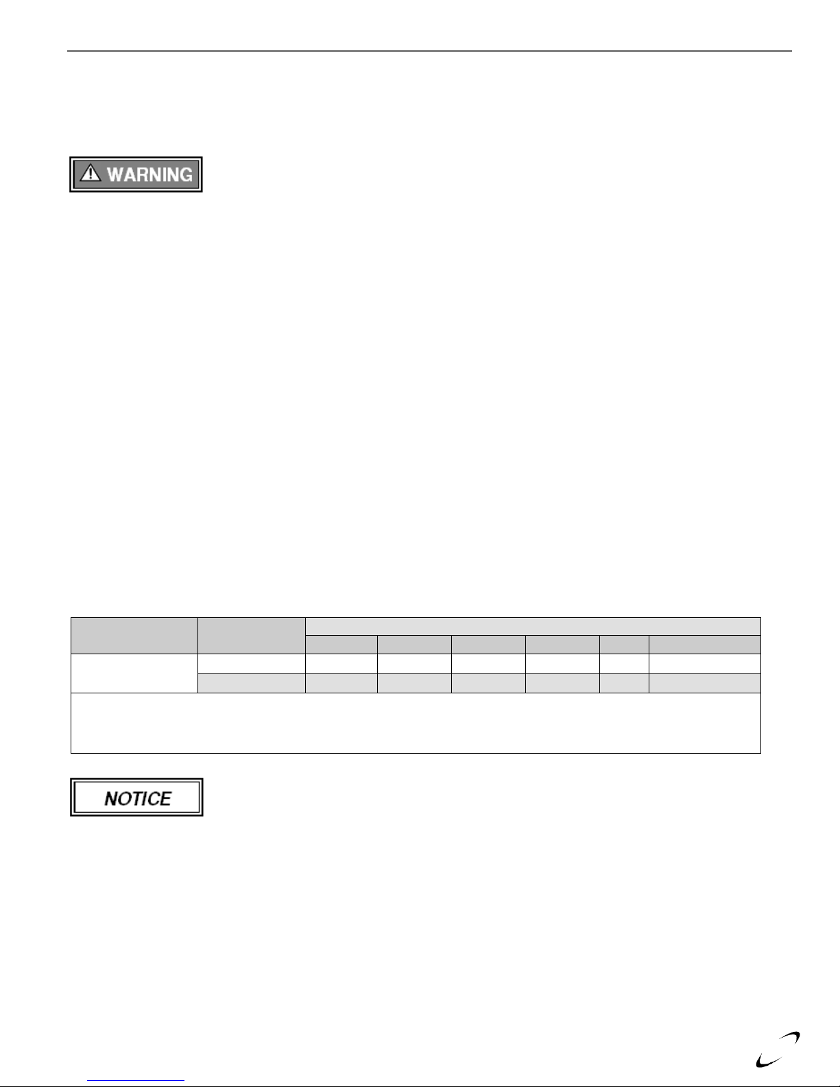
ATTENTION: LIQUEFIED PETROLEUM (LP) PROPANE
The Trinity Ti is factory set to operate with Natural Gas. BEFORE OPERATING WITH PROPANE, the specified LP
Conversion Kit must be installed to convert the appliance so it will operate safely with LP Propane. Listed below is the
correct Natural to LP Propane Conversion Kit number for Trinity Ti100-200 boiler models. Note: kit number 82650-1
contains two LP conversion orifices. The smaller orifice, labeled 34, must be used in the Ti100, while the larger orifice,
labeled 52, must be used in the Ti150 and Ti200.
Liquefied Petroleum (LP) propane gas is heavier than air; therefore, it is imperative that your Trinity Ti boiler is not
installed in a pit or similar location that will permit heavier than air gas to collect. Local Codes may require appliances
fueled with LP gas be provided with an approved means of removing unburned gases from the room. Check your local
codes for this requirement.
Natural to LP Propane Conversion Kit_
NTI Series Model Number Kit Number
Trinity Ti 100, 150, 200 82650-1
Refer to the above, ATTENTION: LIQUEFIED PETROLEUM (LP) PROPANE for correct conversion kit number.
Appliance Vent / Air-Intake Piping
in these instructions. Failure to follow instructions will result in serious injury or death.
Failure to use the appropriate Natural to LP Conversion Kit when operating the Trinity Ti with Propane
will result in extremely dangerous burner operation leading to property damage, serious injury or death.
The Trinity Ti is a “Direct Vent” appliance requiring a “Special Venting System”. Vent and
Combustion-Air Intake piping must be piped to the outdoors, using the vent material and rules outlined
Page 3
Ti Series Installation and Operation Instructions │Trinity
3
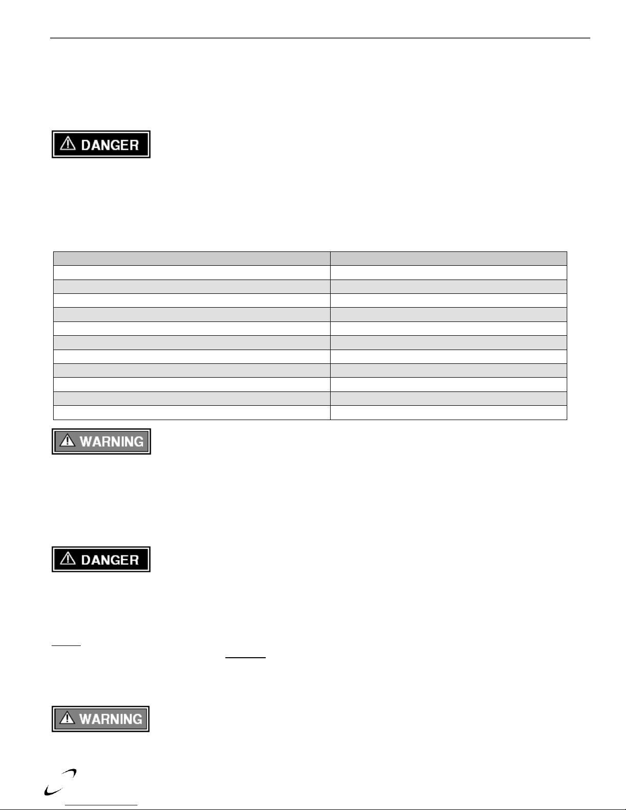
Energy Saving Feature - This boiler is equipped with a feature that saves energy by reducing
the boiler water temperature as the heating load decreases. This feature is equipped with an
override which is provided primarily to permit the use of an external energy management system that serves the
same function. THIS OVERRIDE MUST NOT BE USED UNLESS AT LEAST ONE OF THE FOLLOWING
CONDITIONS IS TRUE :
An external energy management system is installed that reduces the boiler water temperature as the heating load
decreases.
This boiler is not used for any space heating.
This boiler is part of a modular or multiple boiler system having a total input of 300,000 BTU/hr or greater.
This boiler is equipped with a tankless coil.
IN THE STATE OF MASSACHUSETTS ONLY
(a) For all horizontally vented gas fueled equipment installed in every dwelling, building or structure used in whole or
in part for residential purposes, including those owned and operated by the Commonwealth and where the side wall
exhaust vent termination is less than seven (7) feet above finished grade in the area of the venting, including but not
limited to decks and porches, the following requirements shall be satisfied:
1. INSTALLATION OF CARBON MONOXIDE DETECTORS At the time of installation of the side wall
horizontal vented gas fueled equipment, the installing plumber or gas fitter shall observe that a hard wired
carbon monoxide detector with an alarm and battery back-up is installed on the floor level where the gas
equipment is to be installed and on each additional level of the dwelling, building or structure served by the
equipment. It shall be the responsibility of the property owner to secure the services of qualified licensed
professionals for the installation of hard wired carbon monoxide detectors.
a. In the event that the side wall horizontally vented gas fueled equipment is installed in a crawl space or an
attic, the hard wired carbon monoxide detector with alarm and battery back-up may be installed on the next
adjacent floor level.
b. In the event that the requirements of this subdivision can not be met at the time of completion of
installation, the owner shall have a period of 30 days to comply with the above requirements; provided,
however, that during said 30 day period a battery operated carbon monoxide detector with an alarm shall
be installed.
2. APPROVED CARBON MONOXIDE DETECTORS Each carbon monoxide detector as required in
accordance with the above provisions shall comply with NFPA 720 and be ANSI/UL 2034 listed and IAS
certified.
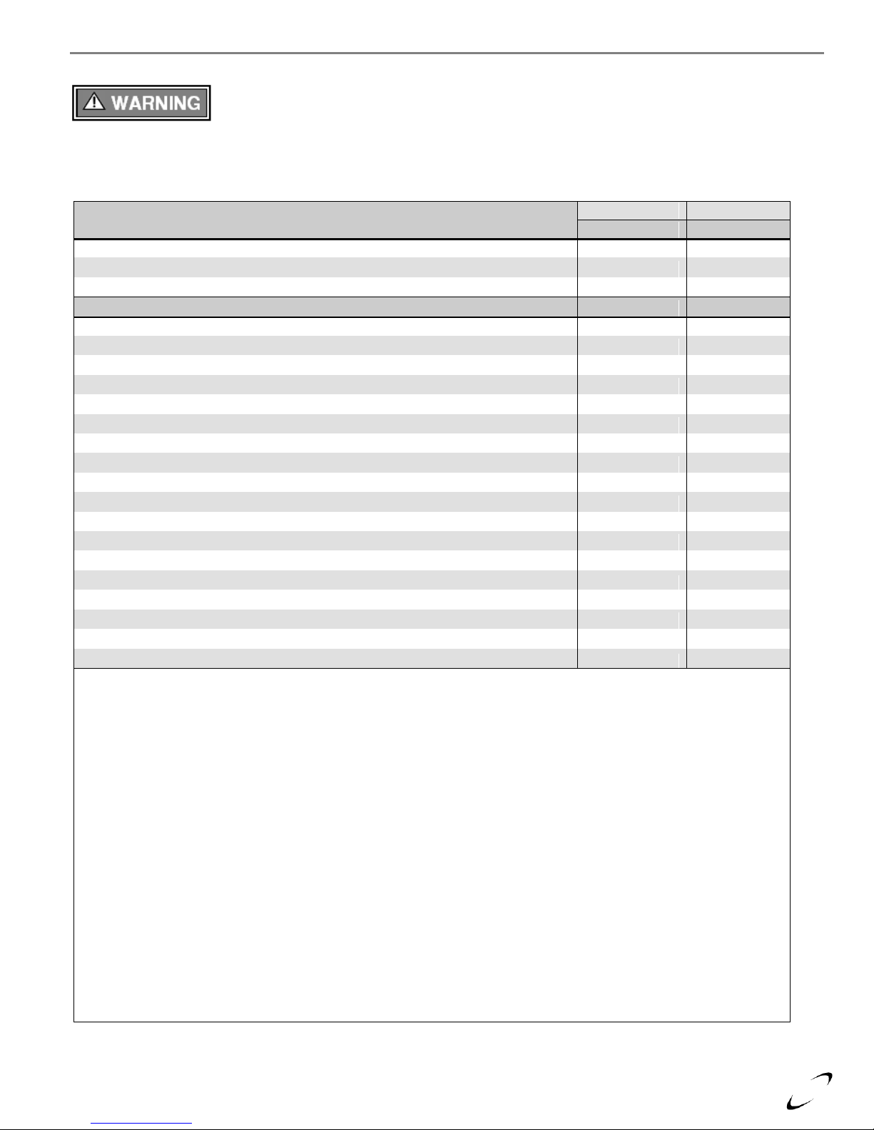
3. SIGNAGE A metal or plastic identification plate shall be permanently mounted to the exterior of the building
at a minimum height of eight (8) feet above grade directly in line with the exhaust vent terminal for the
horizontally vented gas fueled heating appliance or equipment. The sign shall read, in print size no less than
one-half (1/2) inch in size, “GAS VENT DIRECTLY BELOW. KEEP CLEAR OF ALL OBSTRUCTIONS”
(plate included with appliance).
4. INSPECTION The state or local gas inspector of the side wall horizontally vented gas fueled equipment shall
not approve the installation unless, upon inspection, the inspector observes carbon monoxide detectors and
signage installed in accordance with the provisions of 248 CMR 5.08(2)(a)1 through 4.
(b) EXEMPTIONS: The following equipment is exempt from 248 CMR 5.08(2)(a)1 through 4:
1. The equipment listed in Chapter 10 entitled “Equipment Not Required To Be Vented” in the most current
edition of NFPA 54 as adopted by the Board; and
2. Product Approved side wall horizontally vented gas fueled equipment installed in a room or structure separate
from the dwelling, building or structure used in whole or in part for residential purposes.
(c) MANUFACTURER REQUIREMENTS – GAS EQUIPMENT VENTING SYSTEM PROVIDED: When the
manufacturer of Product Approved side wall horizontally vented gas equipment provides a venting system design
or venting system components with the equipment, the instructions provided by the manufacturer for installation of
the equipment and the venting system shall include:
1. Detailed instructions for installation of the venting system design or the venting system components; and
2. A complete parts list for the venting system design or venting system.
(d) MANUFACTURER REQUIREMENTS – GAS EQUIPMENT VENTING SYSTEM NOT PROVIDED:
When the manufacturer of a Product Approved side wall horizontally vented gas fueled equipment does not provide
the parts for venting the flue gases, but identifies “special venting systems”, the following requirements shall be
satisfied by the manufacturer.
Page 4
4
DESCRIPTION
Ti100
Ti150
Ti200
CSA Input Modulation
1
btu/hr [kw]
15,000 - 93,000
[4.4 – 29.3]
25,000 - 150,000 2
[7.3 - 44.0]
25,000 - 199,000
[7.3 - 58.3]
DOE Heating Capacity
1,3
btu/hr [kw]
84,000
[24.6]
136,000
[39.8]
181,000
[53]
Net I=B=R Rating
1,3
btu/hr [kw]
73,000
[21.4]
118,000
[34.8]
157,000
[46]
DOE AFUE %
3
93.5
Water Connections - NPT, in.
1 4
1
Gas Connection - NPT, in.
1/2
Vent/Air-Intake Pipe Diameter 5, in. [mm]
3 or 4 [76 or 102]
Vent/Air-Intake, Max. Length, NG / LP
ft. [m]
105 / 105
[32 / 32]
105 / 50
[32 / 15.2]
105 / 50
[32 / 15.2]
Dimensions H x W x D
in. [mm]
22.5 x 15.5 x 16.75
6
[571 x 394 x 425]
22.5 x 15.5 x 16.75
6
[571 x 394 x 425]
22.5 x 15.5 x 18.25
[571 x 394 x 464]
Approx. Appliance Weight with Water,
lbs [kg]
80 [36.3]
80 [36.3]
110 [49.9]
Notes:
1
Listed Input and Output ratings are at minimum vent lengths at Sea Level. Numbers will be lower with longer venting
and/or altitudes greater then 2000 feet [610 m].
2
The maximum output when operating on LP-Gas is limited to 145,000 Btu/hr [42.5 kW].
3
Based on rating plate input capacities, using standard test procedures prescribed by the U.S. Department of Energy.
Ratings have been confirmed by AHRI (GAMA).
4
Units sold in Canada are 3/4” NPT.
5
Trinity Ti units require a special venting system, use only vent materials and methods detailed in these instructions.
6
Ti100 and 150 units sold in Canada have a depth of 14.75”.
Elevations
2000 ft [610 m]
3000 ft [914 m]
4000 ft [1219 m]
4500 ft [1372 m]
5000 ft [1524 m]
In Canada 1
de-rate by 5%
de-rate by 5%
de-rate by 5%
de-rate by 5%
de-rate % may vary
In USA 2
-
de-rate by 4%
de-rate by 8%
-
de-rate by 12%
Notes:
1
Canada: Altitudes between 2000-4500 ft [610-1372 m], de-rate by 5%. Consult local authorities for de-rating capacities
for altitudes above 4500 ft [1372 m].
2
USA: De-rate capacity by 4% for every 1000 ft [305 m] over 2000 ft [610 m].
Trinity │Installation and Operation Instructions Ti Series
1.0 SPECIFICATIONS
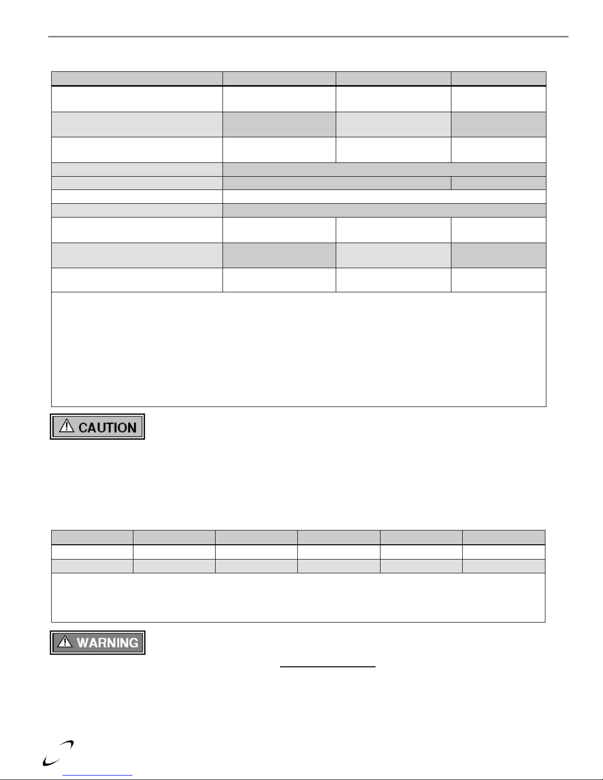
Table 1-1 Specifications
This unit requires two people to lift it or property damage and personal injury may result.
High Altitude Operation
The Trinity is designed to operate at its maximum listed capacity in installations less than or equal to 2000 ft [610 m] above Sea
Level. Since the density of air decreases as elevation increases, maximum specified capacity should be de-rated for elevations
above 2000 ft [610 m] in accordance with Table 1-2.
Table 1-2 De-rate % for High Altitudes
At elevations greater than 2000 feet, the combustion of the appliance must be checked with a calibrated
combustion analyzer to ensure safe and reliable operation. Consult Section 8.0 for instructions on
adjusting the input to provide proper operation. It is the Installers responsibility to check the combustion, and to adjust the
combustion in accordance with Section 8.0. Failure to follow these instructions may result in property damage, serious injury,
or death.
Page 5
Ti Series Installation and Operation Instructions │Trinity
5
Model No.
Clearances
Dimensions - inches [mm]
Front
Top
Sides
Bottom
Rear
Flue/Water Pipe
Trinity Ti100-200
Minimum
24 [610] 1
12 [305]
12 [305]
9 [229] 0 1 [25]
Recommended
24 [610]
24 [610]
24 [610] 2
9 [229] 0 1 [25]
Notes:
1
6” if surface is removable allowing 24” [610 mm] clearance (i.e. closet installation). See “Appliance Ventilation Air
Openings” above.
2
Clearances can be as low as 12” [305 mm] on one side if clearance on the other side is 24” [610 mm].
2.0 BOILER LOCATION
In all cases, the Trinity Ti must be installed indoors in a dry location where the ambient temperature must be maintained above
freezing and below 100F [38C]. Gas components must be protected from dripping, spraying water, or rain during operation and
servicing. Consider the proximity of system piping, gas and electrical supply, condensate disposal drain, and proximity to vent
termination when determining the best appliance location.
Water or flood damaged components must be replaced immediately with new factory-approved
components as failure to do so may result in fire, serious injury, or death.
Appliance Area Ventilation Air Openings
If appliance area clearances are less then the recommended clearances specified in Table 2-1, the appliance area must be
ventilated. Each ventilation air opening must meet the minimum requirements of 1 in2 per 1000 Btu/hr, but not less then 100in2.
The lower ventilation opening must be located within 6” of the floor while the upper opening must be located 6” from the top of
the space.
Closet Installations
For closet installations, it is necessary to provide two ventilation air openings, each providing a minimum area equal to 1 in2 per
1000 Btu/hr, but not less then 100 in2 and within 6” of the top and bottom of the closet door. All Vent and Air-Intake piping
within the closet must be CPVC for both Canada and the US. See Table 2.1 for Minimum and Recommended Clearances.
Alcove Installations
Alcove installations have the same minimum clearances as closet installations, except the front must be completely open to the
room at a distance no greater then 18” [457 mm] from the front of the appliance and the room is at least three (3) times the size of
the alcove. Provided these conditions are met, the appliance requires no extra ventilation air openings to the space. All Vent and
Air-Intake piping within the alcove must be CPVC for both Canada and the US. See Table 2-1 for Minimum and Recommended
Clearances.
Residential Garage Installations
When installed in a residential garage, mount the appliance a minimum of 18” [457 mm] above the floor. Locate or protect the
appliance so it cannot be damaged by a moving vehicle. Check with your local authorities for other possible regulations
pertaining to the installation of an appliance in a garage.
Table 2-1 Minimum Clearances for Installation and Service
The appliance area is considered to be a closet or alcove if the area does not provide the recommended
clearances listed in Table 2-1. See special instructions under Closet and Alcove Installations.
Page 6
6
Products to Avoid
Contaminated Sources to Avoid
Antistatic fabric softeners, bleaches, detergents, cleaners
Laundry facilities
Perchloroethylene (PCE), hydrocarbon based cleaners
Dry cleaning facilities
Chemical fertilizer, herbicides/pesticides, dust, methane gas
Farms or areas with livestock and manure
Paint or varnish removers, cements or glues, sawdust
Wood working or furniture refinishing shops
Water chlorination chemicals (chloride, fluoride)
Swimming pools, hot tubs
Solvents, cutting oils, fiberglass, cleaning solvents
Auto body or metal working shops
Refrigerant charge with CFC or HCFC
Refrigerant repair shops
Permanent wave solutions
Beauty shops
Fixer, hydrochloric acid (muriatic acid), bromide, iodine
Photo labs, chemical / plastics processing plants
Calcium Chloride
De-Icing / Ice Melters
Cement powder, crack fill dust, cellulose, fiber based insulation
Concrete plant or construction site
Trinity │Installation and Operation Instructions Ti Series
3.0 GENERAL VENTING
The Trinity Ti is a “Direct Vent” appliance requiring a “Special Venting System” designed for pressurized venting. Both the
Vent and Air-Intake piping must be piped to the outdoors, using the vent material and rules outlined in this section. Under no
conditions may this unit vent gases into a masonry chimney, unless it is vacant, and utilizes the approved venting material and
rules described in this section. Installations must comply with the National Fuel Gas Code, ANSI Z223.1 (U.S.) or CSA B149.1
(Canada) and local requirements.
Vent and Air-Intake to be piped separately. The Trinity Ti cannot share a common vent or air-intake
with multiple appliances. Failure to comply will result in serious injury or death.
Combustion Air-Intake Contamination
Be careful not to locate the Air-Intake termination in an area where contaminants can be drawn in and used for combustion.
Combustion air containing dust, debris or air-borne contaminants will drastically increase the required maintenance and may
cause a corrosive reaction in the Heat Exchanger which could result in premature failure, fire, serious injury, or death. See Table
3-1 for a list of areas to avoid when terminating air-intake piping:
Table 3-1 Corrosive Products and Contaminant Sources
Do not store or use gasoline or other flammable vapors and liquids in the vicinity of this or any other
appliance. Failure to follow instructions may result in serious injury or death.
Flammable Solvents and Plastic Piping
Due to the extremely flammable characteristics of most glues, cements, solvents and primers used in the process of joining plastic
vent and air-inlet pipe, explosive solvent vapors must be evacuated from the vent and air-intake prior to start-up. Avoid using
excess cement or primer that may lead to pooling inside the pipe assembly. Freshly assembled piping should be allowed to cure
for a minimum of 8 hours before applying power to the gas fired appliance. Refer to Mandatory Pre-commissioning Procedure
for Plastic Venting in this section.
Flammable Cements and Primers – It is the installers’ responsibility to familiarize themselves with
the hazards associated with explosive solvents and to take all precautions to reduce these risks. Failure
to follow these instructions can cause explosions, property damage, injury or death.
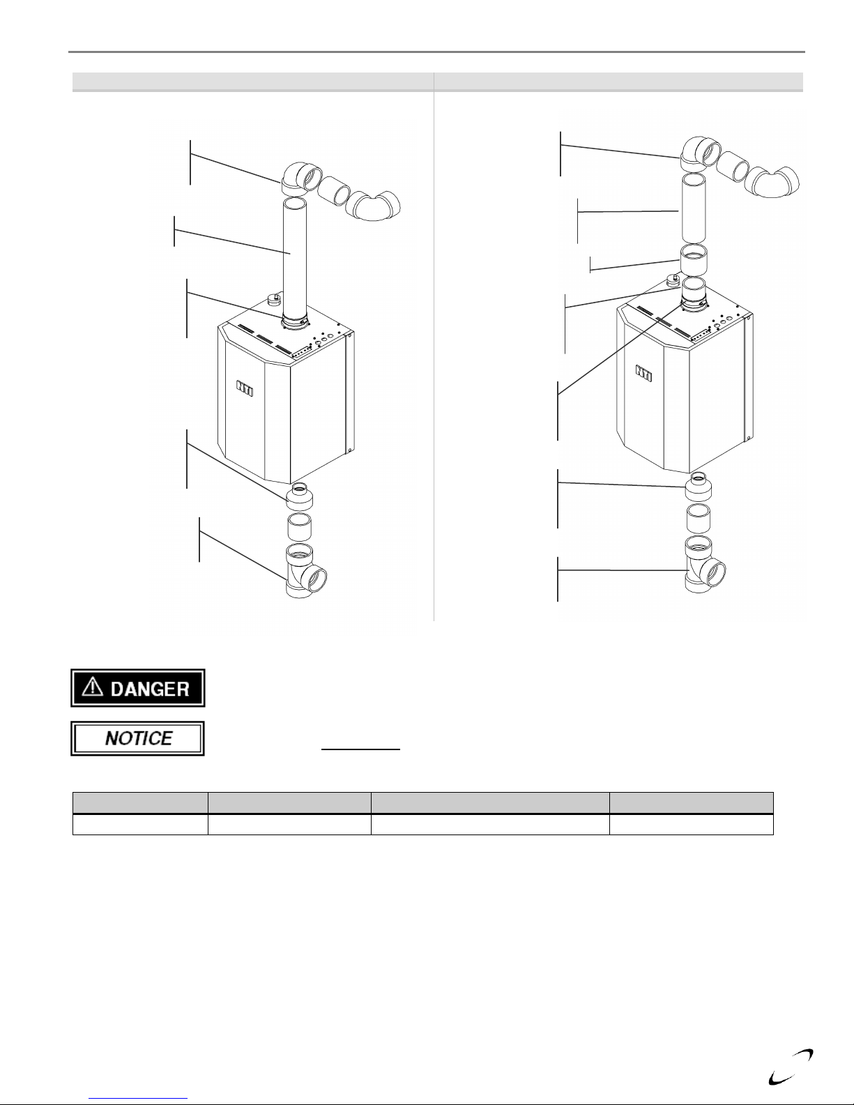
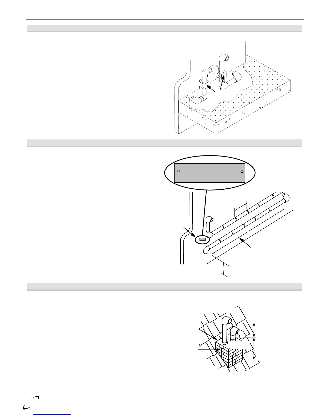
Near Boiler Vent/Air-Intake Piping
Each Trinity Ti is equipped with a short piece of approved CPVC vent pipe. Insert one end into the boiler flue outlet adapter and
cement the other to field venting (see Table 3-3 for approved venting material). The CPVC vent pipe should extend fully into the
boiler flue outlet adapter (see Table 3-2). DO NOT insert PVC pipe directly into the flue outlet connection as it can deform from
the clamping force of the gear clamp. Ensure that the venting system does not apply a load or strain on the boiler flue outlet
adapter. The manufacturer recommends using two elbows to create a “swing joint” to reduce potential strain on vent piping and
cemented joints. See Figure 3-1 for illustration.
Gasket Seating - Improper seating can cause leakage and eventual failure of the sealing gasket. Failure
to follow these instructions may result in serious injury or death.
Page 7
Ti Series Installation and Operation Instructions │Trinity
7
Swing Joint
to attain slope in
horizontal runs
Exhaust Vent
3”PVC, (check local
codes and Table 3-3)
Coupling - 3”PVC
Transition Piece
3” CPVC, minimum
5” long (factory
supplied)
Flue Outlet
Stainless Steel
Adapter (factory
supplied)
Air Inlet Adapter
Immediately
adapt from 1-1/2”
to 3”
Cleanout
Recommended on
Air Inlet Piping
Figure 3-1(a)
Figure 3-1(b)
Near Boiler Venting (CPVC)
Near Boiler Venting (PVC)
Model No.
CPVC Vent Pipe Size
CPVC Transition Vent Pipe Length
Full Insertion Depth
Trinity Ti100-200
3”
Minimum 5” [127 mm]
2-7/8” [73 mm]
Flue Outlet
Stainless Steel
Adapter (factory
supplied)
Swing Joint
to attain slope in
horizontal runs
Exhaust Vent
3”CPVC
Air Inlet Adapter
Immediately
adapt from 1-1/2”
to 3”
Cleanout
Recommended on
Air Inlet Piping
Air-Inlet - check with applicable local codes for acceptable pipe material.
Exhaust venting must be supported to reduce strain on piping joints. Failure to follow these instructions
may result in result in damage, serious injury or death.
In Canada, the first 3 ft (915 mm) of vent piping must be readily accessible for inspection.
Table 3-2 Mandatory Vent Pipe Transition Piece
Page 8
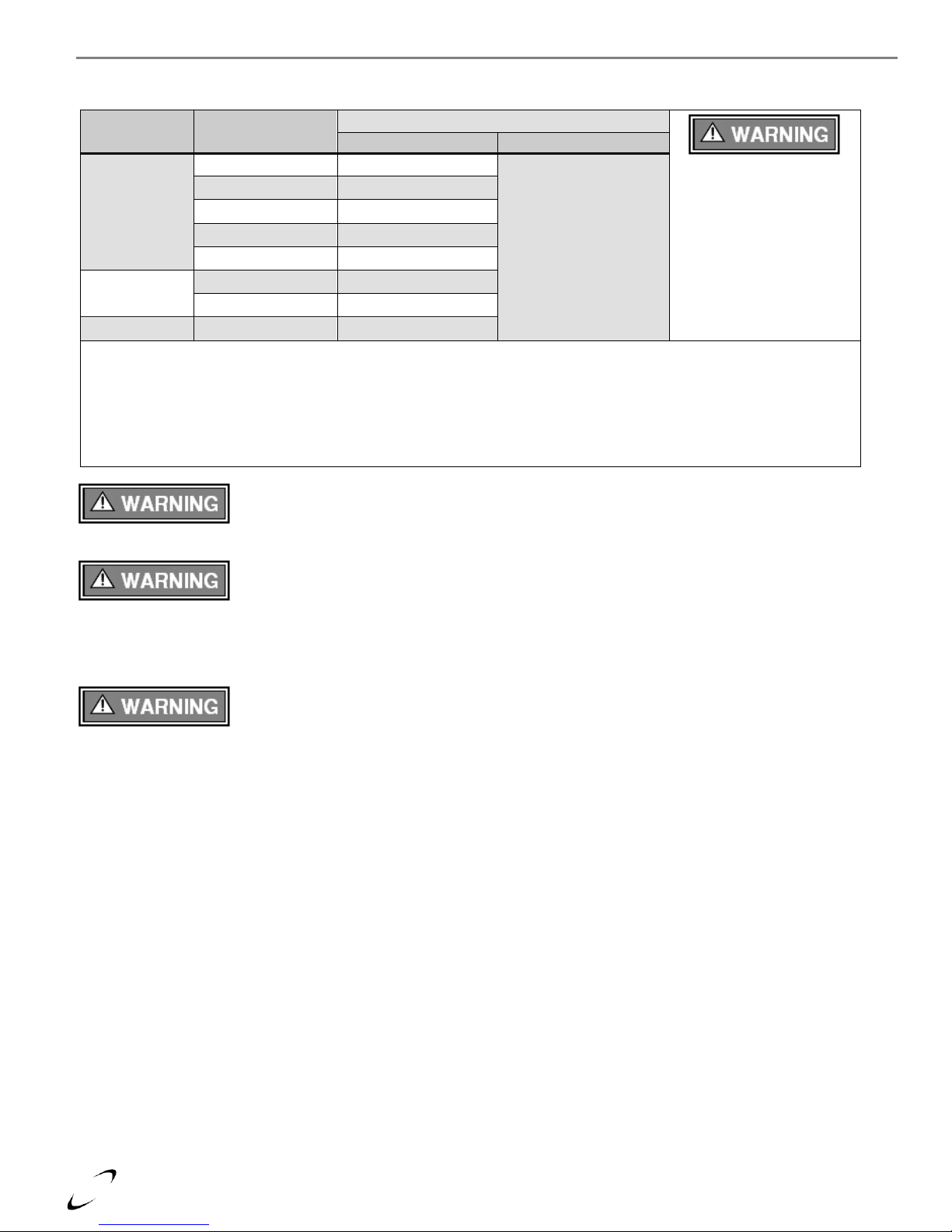
8
Items 1
Materials
2, 3
Installation Standards
All Vent and Air-Intake
materials installed on gas
fired appliances in CAN/US
must meet the Standards
listed in Table 3-3. Failure
to comply could result in
fire, serious injury or death.
United States
Canada 4
Vent Piping
and Fittings
PVC - DWV
ANSI/ASTM D2265
All venting material in
Canada must be
ULC S636 approved.
See Note 4 below for
appropriate temperature
applications.
PVC Schedule 40
ANSI/ASTM D1785
CPVC Schedule 40
ANSI/ASTM F441
AL29-4C
UL-1738
Polypropylene (PP)
n/a
Pipe Cement
PVC
ANSI/ASTM D2564
CPVC
ANSI/ASTM F493
Primers
PVC / CPVC
ANSI/ASTM F656
Notes:
1
Refer to Table 3-4 for Allowable Vent and Air-Intake Pipe Sizes and Lengths.
2
PVC venting (exhaust and air-intake) is not permitted within the Closet/alcove of a Closet/alcove installation.
3
The Air-Intake does not require high temperature pipe material. Check applicable local codes for acceptable materials.
4
ULC S636 PVC is approved for flue gas temperatures up to 149oF (65oC) and must only be used for low temperature
applications. High temperature applications requiring appliance supply water temperatures greater than 140oF (60oC)
must use ULC S636 CPVC, PP or AL29-4C.
Trinity │Installation and Operation Instructions Ti Series
Vent/Air-Intake Pipe Material
Table 3-3 Acceptable Vent and Air-Intake Pipe Material
The use of cellular core PVC (ASTM F891), cellular core CPVC, or Radel®
(polyphenolsulfone) in the exhaust venting system is prohibited. Failure to follow these
instructions may result in property damage, personal injury or death.
Covering non-metallic vent pipe and fittings with thermal insulation is prohibited. Failure to
follow these instructions may result in property damage, personal injury or death.
Mandatory Pre-commissioning Procedure for Plastic Venting
1) Working with the power turned off to the boiler, completely install the vent and air intake system, securely cementing joints
together. If possible, allow primers/cements to cure for 8 hours before firing the burner. If curing time is less than 8 hours,
proceed with Steps 2 through 6.
2) Maintain the boiler gas supply shut-off valve in the off position.
3) Disconnect electrical leads to the Hot Surface or Spark Igniter. Ensure the cables are placed in a fashion where they will not
arc to ground or other conductor.
4) Turn power on to the boiler and apply a heat demand.
5) Allow for 3 complete trials for ignition, consisting of pre and post purge of the combustion blower, until an ignition lockout
occurs. Repeat the process two more times (i.e. 9 complete ignition sequences in total).
6) Turn power off and reconnect the electrical leads to the Igniter.
Do not apply power to the boiler prior to Step 4 in the Mandatory Pre-commissioning Procedure for
Plastic Venting.
Page 9
Ti Series Installation and Operation Instructions │Trinity
9
Model
Pipe Size
Gas
Length
ft. [m]
Number of Elbows (90’s or 45’s) and Equivalent Feet [Meters]
1 2 3 4 5 6 7 8 9
Ti150
Ti200
3”
LP
50
[15.2]
45
[13.7]
40
[12.2]
35
[10.7]
30
[9.1]
25
[7.6]
20
[6.1]
15
[4.6]
10
[3.0]
5
[1.5]
3”
NG
105
[32]
100
[30.5]
95
[28.9]
90
[27.4]
85
[25.9]
80
[24.4]
75
[22.9]
70
[21.3]
65
[19.8]
60
[18.3]
4”
NG
& LP
105
[32]
100
[30.5]
95
[28.9]
90
[27.4]
85
[25.9]
80
[24.4]
75
[22.9]
70
[21.3]
65
[19.8]
60
[18.3]
Ti100
3” or 4”
NG
& LP
105
[32]
100
[30.5]
95
[28.9]
90
[27.4]
85
[25.9]
80
[24.4]
75
[22.9]
70
[21.3]
65
[19.8]
60
[18.3]
NTI
P/N
IPEX
P/N
Description
1,2,4
Vent Kit
Material
Kit
Connection
Vent Option
Roof
Wall
82666
196116
Concentric Vent Termination Kit (CAN)
4,5
ULC S636
PVC
3"
84355
196021
4"
n/a
197009
Concentric Vent Termination Kit (CAN)
4,5
ULC S636
CPVC
3"
84357
196985
Low Profile Termination Kit
(Flush Mount)
PVC
3"
84358
196986
4"
Notes:
1
Instructions included with termination kits contain more detailed assembly and installation instructions.
2
Clearance requirements in this manual supersede those of the instructions included with the vent terminal.
3
Terminal MUST be cemented together and to the vent pipes during installation.
4
Certified to ULC S636.
5
Vent Screen provided with boiler may be used with the IPEX Concentric Vent Kits; otherwise use IPEX vent screens (3"
vent screen P/N 196051; 4" vent screen P/N 196052).
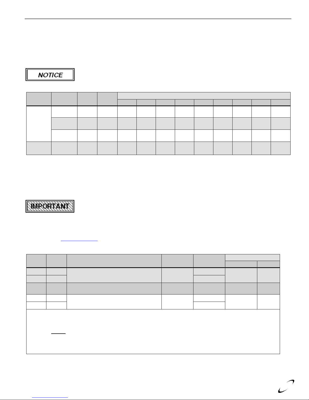
Vent and Air-Intake Pipe Length Determination
Use Table 3-4 to determine the maximum pipe length that can be used. The table calculates sweep, 90º elbows, and 45º elbows at
5 equivalent feet [1.52 m] each. Note: models Ti150-200 have limitations when operating with Propane Gas (LP).
Example: A Ti200 can be installed with 105 equivalent feet [32 m] of air-intake piping and 105 equivalent feet [32 m] of vent
piping when operating with Natural Gas. When operating with Propane Gas (LP), the maximum vent length in equivalent feet is
limited to 50’ (3” pipe).
The length of one vent pipe (intake or exhaust) may not exceed the length of the other vent pipe by
more than 20 equivalent feet (6.1 m).
Table 3-4 Allowable Vent and Air-Intake Pipe Size and Lengths
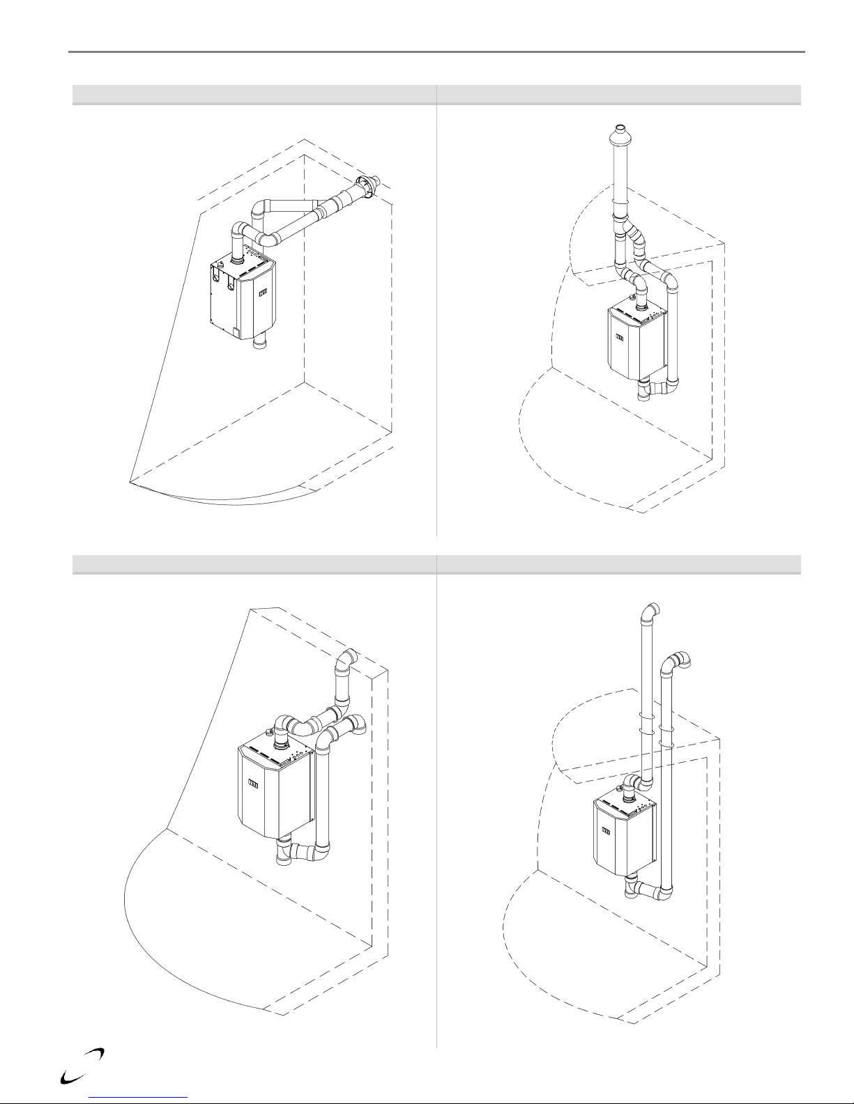
Termination Options
The venting system of the Trinity Ti may be terminated using field supplied piping to construct a “Two-Pipe” termination, see
Figures 3-3, 3-4a, 3-6, 3-9, 3-10 and 3-11. Alternatively, the venting may be terminated used a factory kit, either “Concentric”
(see Figures 3-2, 3-4b, 3-5 and 3-7) or “Low Profile” (see Figure 3-8). The Concentric Vent Termination Kit can be either Roof
or Sidewall terminated, while the Low Profile Termination Kit may only be Sidewall terminated. See Table 3-5 for details on the
optional termination kits.
Venting Options - Due to potential moisture loading (build-up) along the exterior wall, sidewall
venting may not be the preferred venting option. See Figs 3-2(b) and 3-3(b).
Optional Termination Kits
Kits certified with the Trinity Ti are listed in Table 3-5 and available from IPEX and/or NTI. For more information on System 636
Concentric Vent Kits or wholesaler locations contact IPEX directly. USA: 1-800-463-9572 or www.IPEXamerica.com │ CAN: 1866-473-9462 or www.ipexinc.com.
Table 3-5 Optional Vent Termination Kits
Page 10
10
Figure 3-2(a)
Figure 3-2(b)
Concentric Side Wall Termination (Optional Kit)
Concentric Roof Termination (Optional Kit)
Figure 3-3(a)
Figure 3-3(b)
Two-Pipe Side Wall Termination
Two-Pipe Roof Termination
Trinity │Installation and Operation Instructions Ti Series
Page 11
Ti Series Installation and Operation Instructions │Trinity
11
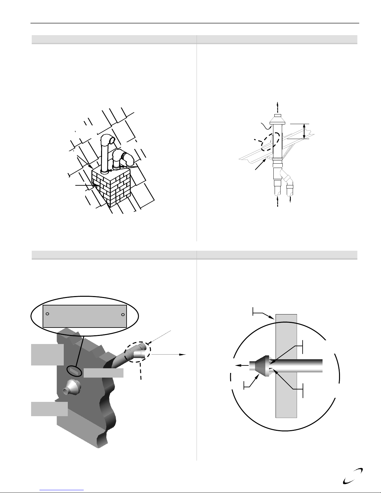
Labeling and Identification – Roof Top Terminations
Figure 3-4(a)
Figure 3-4(b)
Two-Pipe Roof Top Termination
Concentric Vent Roof Top Termination
Two-pipe terminations typically penetrate the roof surface.
An alternative is to use an existing chimney as a chase way.
See Figure 3-11 for more details.
To prevent water leakage, install adequate roof weather seal
flashing (not included) around roof penetration as shown.
Labeling and Identification – Concentric Vent Side Wall Terminations
Figure 3-5(a)
Figure 3-5(b)
Concentric Vent Side Wall Termination
Concentric Vent Detail
Insert vent screen between the end of the boiler exhaust vent
and the end cap as shown. The End Cap
Insert vent screen between the end of the boiler exhaust vent
and the end cap as shown. The End Cap must be secured to
the vent pipe via cement or stainless steel screws.
Warning Plate
From
boiler
To boiler airinlet
connection
Exhaust Vent
Outlet (center)
Gas Vent Directly Below
Keep Free of Obstructions
Concentric
“Y” Fitting
Combustion
Air-Inlet
(perimeter)
Support
(field
supplied)
To boiler
air-inlet
connection
From boiler
exhaust
Air-Inlet
Roof weather
seal flashing
(field supplied)
24” [610 mm]
from terminal
end cap vanes
Exhaust Vent
Exhaust
Vent
Air-Inlet
Chimney
Cap
Existing
Chimney
(used as a
chase way)
Flashing
Exhaust
Vent
Combustion
Air Inlet
End Cap
Vanes (typical)
End Cap
Exterior Wall
Page 12
12
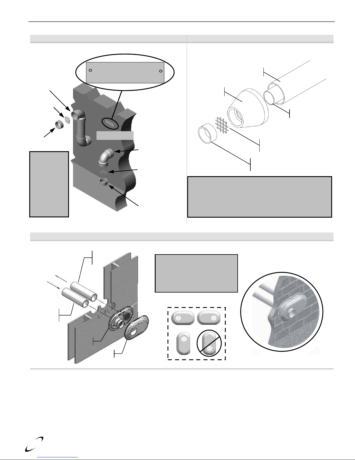
Labeling and Identification – Two Pipe Side Wall
Labeling and Identification – Optional Kit
Figure 3-6
Figure 3-7
Two-Pipe Side Wall Termination
Concentric Vent Termination Kit
Labeling and Identification – Low Profile Termination Kit
Figure 3-8
Low Profile Termination Kit
Warning Plate
Exhaust
Vent
Vent
Screen
Vent Screen
Insert vent
screen into
socket joint of
termination
elbow. Secure
by cementing
a short piece
of venting into
the socket.
Venting
Vent
Screen
Gas Vent Directly Below
Keep Free of Obstructions
Combustion
Air-Inlet
Venting
Fully Assembled
and Installed
Air-Inlet
Piping
Exhaust
Venting
Approved Orientation
Base
Cap
Low Profile Termination Kit
The vent /air-inlet pipes are field
supplied. Vent screens are build
in. Major components provided in
Low Profile Kit include: base, cap,
s.s. screws, and plastic anchors.
Concentric Vent Termination Kit
Insert Vent Screen into the End Cap from the outside,
followed by a short piece of vent pipe to retain the Vent
Screen in place. The End Cap must be secured to the
Exhaust Vent via cement or stainless steel screws. Refer to
Figure 4-12 for more details.
Air Inlet Pipe
Exhaust Vent
Vent Screen
(Included w. boiler)
End Cap
Retaining Exhaust
Pipe Piece
Trinity │Installation and Operation Instructions Ti Series
Page 13

Ti Series Installation and Operation Instructions │Trinity
13
Venting Rules and Guidelines
1. Prevailing Winds: Ensure the vent is located where it will not be exposed to normal prevailing winds.
2. Combustion Air-Intake Contamination: Air for combustion must be drawn from outdoors from an area free of dust and
contaminants. Combustion air containing chemicals such as chloride, fluoride, bromine or iodine or dust and debris will
cause corrosion damage of the heat exchanger voiding your NTI warranty. Refer to Table 3-1 for a list of corrosive
products and contaminants sources to avoid.
3. Vertical Separation: The exhaust must be a minimum of 18” [457 mm] above the air inlet, and the air inlet must always be
a minimum of 12” [305 mm] plus snow allowance above any surface that will support snow. (Two feet plus snow allowance
is highly recommended). Consult your weather office, for the maximum typical snowfall for your region.
Example: New Brunswick Canada - typical maximum snowfall is 19”, thus the inlet must be (12”+19”) = 31” above grade
and exhaust must be (31”+18”) = 49” above grade.
4. Horizontal Separation: The horizontal distance between the inlet and exhaust must be a minimum of 4” [102 mm] center
to center. When the horizontal distance between the inlet and exhaust is greater than 12” [305 mm], the difference in
horizontal distance must be determined and the vertical separation increased by the same amount.
Example: The horizontal distance (HD) = 24” [610 mm] and the vertical separation (VSmin) = 18” [457 mm], the new
vertical separation (VSnew) can be calculated using the following equation:
VSnew = (HD - 12”) + VS, where VSnew = (24” - 12”) + 18” = 30”.
(If the horizontal distance is greater than 6’ [1.83 m], no additional vertical spacing is required. Vertical separation is never
required to be greater than 36” [915 mm].
5. Wall Flashing: Under normal operating conditions this boiler will produce a plume of white gases, and should be taken into
consideration when selecting an adequate location. A 36” [915 mm] diameter stainless, plastic, or vinyl shield can be used to
flash the exterior of the residence.
6. Flue Gas Hazard: Position the vent termination where vapors cannot make accidental contact with people and pets or
damage nearby shrubs and plants.
7. Elbow Extensions: Elbows on outside of wall must be no more than ½” [13 mm] away from the wall.
8. Vent Sloping: All indoor exhaust piping must be on a slope back to the boiler a minimum of ¼” per linear foot of vent [6.25
mm per linear 305 mm]. For applications where excessive condensation is possible ½” per linear foot [13 mm per linear 305
mm] is recommended.
9. Vent Supports: Where required Vent and Air-intake piping shall be secured to the wall for more rigidity. All interior vent
pipe shall be supported a minimum of every 36” [915 mm].
10. Roof Exhaust: In all roof applications the discharge must point away from the pitch of the roof.
11. Roof Flashing: Install adequate flashing where the pipe enters the roof, to prevent water leakage.
12. Rain Cap: Install and seal a rain cap over existing chimney openings, in vacant chimney applications.
13. Venting Below Grade: For installations that exit the wall below grade refer to Figure 3-9.
14. Vent Screens: Install factory supplied vent screens on the outside of the last elbow for both the inlet and exhaust vent
terminal elbows. Install the screen into the female opening of the elbow. Then cut a small piece of pipe to sandwich the
screen into the elbow. NOTE be sure that the small piece of pipe cut, does not extend past the end of the elbow. Two
screens are provided in the package. See Figures 3-6 and 3-7. Vent screens are included in Optional Termination Kits.
15. Pipe Sizing: It is extremely important that the intake and exhaust vent piping be adapted to the appropriate size immediately
upon exiting the boiler cabinet. Refer to Figure 3-1 and Table 3-4.
16. Condensate Hazard: Do not locate vent over public walkways, driveways or parking lots. Condensate could drip and
freeze resulting in a slip hazard or damage to vehicles and machinery.
17. Warning Plate: Install the warning plate “Gas Vent Directly Below”, directly above (within 4 ft [1.22 m] vertically) the
location of the air inlet pipe, so it is visible from at least 8 ft [2.4 m] away. See Figures 3-5a and 3-6.
18. Wall Thickness: Direct vent terminations are designed to work with any standard wall thickness. Installation guidelines for
min/max wall thickness are as follows: Min.= 1” [25mm], Max.= 60” [1.52 m].
19. Venting Options: Due to potential moisture loading (build-up) along the exterior wall, sidewall venting may not be the
preferred venting option. Refer to Figures 3-2(b) and 3-3(b) for roof top venting options.
Page 14
14
Figure 3-9
Venting Below Grade
For installations that exit the wall below grade:
1. Excavate site to a point below where the pipes are to
exit as shown.
2. Ensure that the wall is fully sealed where the pipes
penetrate the wall.
3. The Vent/Air-intake piping MUST be secured to the
side of the building above grade, as shown, to provide
rigidity.
4. NTI Provides a mounting bracket PN. 82075 for
securing the exhaust pipes.
5. Ensure that the Vent/Air-Intake clearances are
maintained, see Section 4.0 for details.
Figure 3-10
Outdoor Horizontal Venting
Vent piping outside the Building is permitted under the
following conditions:
1. The maximum length outside the building is 20 feet [6.1
m]. Note that outdoor length must be included in the
overall vent length calculation.
2. All normal termination clearances are maintained.
3. The pipe is supported every 24” [610 mm].
4. The exhaust and inlet are sloped back to the boiler ½”
elevation for every linear foot [13 mm for every linear
305 mm].
Figure 3-11
Existing Chimney Chase Way
It is permissible to use an existing chimney as a chase way to
run the Vent/Air-Intake piping as long as:
1. The chimney is not being used by any other boiler.
2. Flue gases don’t enter the vacant chimney.
3. Only Trinity certified venting materials are used, see
Section 3.0.
4. Vent lengths are within the maximums specified.
5. The top of the chimney is capped and the Vent/Air-Inlet
pipes are flashed to prevent leakage into the vacant
chimney.
Air-Inlet
Existing
Chimney
(used as a
chase way)
Chimney
Cap
Exhaust Vent
Exhaust Vent Min.
18” [457 mm]
above air-inlet
Air-Inlet
Min. 12” [305 mm]
above roof and
snow level
Supports every
24” [610 mm]
12” [305 mm] plus snow
allowance above grade
Air-Inlet
Maximum of 20 ft
[6.1 m] is permitted
for piping outside a
building.
Apply
Warning
Plate
here
Exhaust
Vent
Gas Vent Directly Below
Keep Free of Obstructions
Exhaust Vent
Air-Inlet
Mounting
Bracket
Trinity │Installation and Operation Instructions Ti Series
Page 15
Ti Series Installation and Operation Instructions │Trinity
15
Clearances to Air-Inlet Termination
Canada 1
USA 2
Min. Distance
Min. Distance
A
Above grade/roofline and snow level 8
12 in.
305 mm
12 in.
305 mm
B
Above roof line - Concentric Vent
6, 11, 13
24 in.
610 mm
24 in.
610 mm
C
To exhaust vent from any other boiler
36 in.
915 mm
12 in.
305 mm
Clearances to Exhaust Vent Termination
Min. Distance
Min. Distance
D
Minimum vertical separation above air inlet 9
18 in.
457 mm
18 in.
457 mm
E
Minimum horizontal separation from air inlet 3
4 in.
102 mm
4 in.
102 mm
F
Window, door or building opening
36 in.
915 mm
12 in.
305 mm
G
To combustion air inlet from any other boiler
36 in.
915 mm
12 in.
305 mm
H
Non-mechanical air supply inlet to building
36 in.
915 mm
12 in.
305 mm
I
Mechanical air supply inlet to building 4
6 ft.
1.83 m
3 ft.
915 mm
J
Soffit, overhang, eave or parapet
24 in.
610 mm
24 in.
610 mm
K
Soffit vent or vent opening in an overhang, eave or parapet
6 ft.
1.83 m
6 ft.
1.83 m
L
Outside corner 10
- - -
-
M
Inside corner of an L-shaped structure (including walls and fences)
36 in.
915 mm
36 in.
915 mm
N
Electric meters, gas meters, regulators and relief equipment
6 ft.
1.83 m
4 ft.
1.22 m
P
Each side of center line above or below meters, regulators and relief devices 5
36 in.
915 mm
36 in.
915 mm
Q
Above a paved sidewalk, driveway, or parking lot on public property if adjacent 12
7 ft.
2.13 m
7 ft.
2.13 m
R
Above a sidewalk, driveway, or parking lot on public property
X X X
X
S
Above a sidewalk, driveway on private property between / serving both dwellings
X X X
X
T
Under a concrete veranda, porch, deck, or balcony 7
24 in.
610 mm
24 in.
610 mm
U
Above, under or near exterior stairs
X X X
X
V
Into a canopy or carport
X X X
X
Notes:
1 - Canadian installations must comply with the current CSA B149.1 Natural Gas and Propane Installation Code and local
building codes.
2 - US installations must comply with current ANSI Z223.1/ NFPA 54 National Fuel Gas Code and local building codes.
3 - Horizontal separation center-to-center (c.c.) 4”-12” (102-305 mm). Refer to “Venting Rules and Guidelines” for
horizontal separation > 12” c.c. as it may impact vertical separation clearances.
4 - For US installations, an exhaust vent may be 3 ft above a mechanical air supply inlet if within 10 ft. [3 m] horizontally.
5 - Horizontal clearance must be observed up to a height of 15 ft. [4.6 m] above/below the meter, regulator, or relief devices.
6 - Concentric Vent must protrude from the roof precisely 24” [610 mm] measuring from the terminal end-cap vanes.
7 - Permitted if veranda, porch, deck, or balcony is made of concrete and a minimum of two sides are fully open beneath.
8 - 24” is the recommended snow level allowance above grade/roofline or any surface that will support snow, debris, or ice
(i.e. for roof venting clearances - roofline and snow level). If living in a snowfall region, consult your local weather
office for the maximum typical snowfall for your area.
9 - Note that the vent must maintain a minimum vertical distance above the air inlet. Example: Vent height = 18” (457
mm) above air inlet + 12” (305 mm) for air inlet above grade/roof line and snow level = 30” (762 mm) above grade and
snow level.
10 - Clearances to an outside corner to be in accordance with local installation codes.
11 - In Canada, concentric vent materials are subject to approval by local inspectors. See Termination Kits in Section 3.0.
12 - Above public walkways, driveways or parking lots if adjacent to it and condensate cannot drip, freeze, or create a hazard.
13 - Contact the manufacturer for special exemptions relating to multiple boiler installations using concentric vents.
4.0 VENT/AIR-INTAKE TERMINATION CLEARANCES
The quick reference table below is to be read in conjunction with the numbered notes as indicated,
Figures 4-1 through 4-6, and the Venting Rules and Guidelines in Section 3.0. The instructions detailed
in this section are a combination of Trinity Ti specific and National Gas Code restrictions. Compliance alone doesn’t insure a
satisfactory installation as good common sense must also be applied. Failure to follow these instructions may result in fire,
property damage, serious injury or death.
Table 4-1 Termination Clearances Quick Reference Table
Page 16
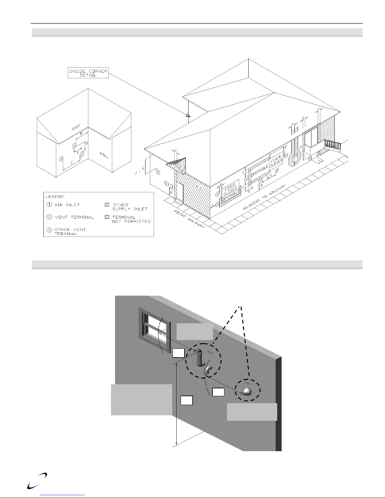
16
G – Letter represents a specific Termination Position. Refer to Table 4-1 for corresponding termination clearances.
Concentric Vent
Termination
Q
Two-Pipe
Termination
F
Clearance “Q”
Adjacent to Public
Walkway or Driveway
Minimum 7ft [2.13 m]
G
Clearances “F” and “G”
Canada – Minimum 3 ft [915 mm]
The US – Minimum 1 ft [305 mm]
Trinity │Installation and Operation Instructions Ti Series
Figure 4-1
Termination Clearances Quick Reference Diagram
Illustrations of Termination Clearances
Side Wall Termination - Clearances Above Grade
Figure 4-2
Page 17
Ti Series Installation and Operation Instructions │Trinity
17
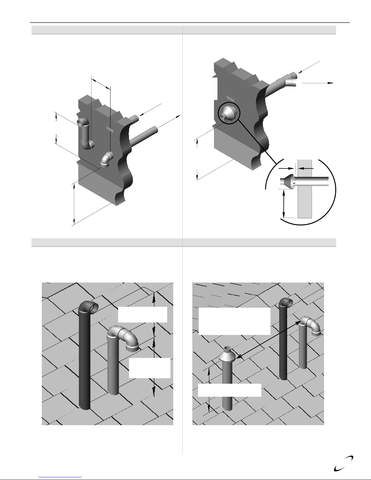
Figure 4-3 Typical
Figure 4-4
Two-Pipe Side Wall Clearances
Concentric Vent Side Wall Clearances
Figure 4-5
Figure 4-6
Two-Pipe Roof Top Clearances
Concentric Vent Roof Top Clearances
Two-pipe systems can be vented thorough the roof.
Minimum heights above snow level still apply.
The same clearances apply to roof-top terminations as for
two-pipe sidewall terminations.
Vertical
Separation
Horizontal Separation
4-12” [102 mm – 305 mm] or
greater than 36” [915 mm]
From boiler
exhaust
Minimum
12” [305 mm]
above grade
and snow level
To boiler
air-inlet
connection
Minimum 18”
[457 mm]
To boiler
air-inlet
connection
Exhaust from
boiler
Wall clearance
must be 1” [25
mm] from end
cap vanes to
outside of wall
Minimum
12” [305 mm]
above grade
and snow
Exhaust
Vent Outlet
(center)
Combustion
Air-Inlet
(perimeter)
Min. 12” [305 mm]
above grade and
snow level
MIN. 18” [457 mm]
above air-intake
MIN. 12”
[305 mm] above
snow level
24” [610 mm] above roof
from end cap vanes
Clearances from exhaust to
another combustion air inlet
Canada – Min. 3 ft [915 mm]
The US – Min. 1 ft [305 mm]
Page 18

18
Trinity │Installation and Operation Instructions Ti Series
Extra precaution must be taken to adequately support the weight of the Vent/Air-Intake piping in
applications using roof-top terminations. Failure to follow these instructions may result in venting or
boiler component failure resulting in flue gas spillage leading to property damage, serious injury or death.
Under no circumstances may an existing chimney or chase-way be used to vent or provide combustion
intake air to a Trinity Ti. Failure to follow instructions will result in fire, property damage, serious
injury or death.
Removing an Existing Boiler from Common Venting System
Do not install the Trinity Ti into a common venting system with any other boilers. Failure to comply
with this warning will cause flue gas spillage and leech carbon monoxide emissions into the
surrounding air resulting in serious injury or death.
When an existing boiler is removed from a common venting system, the common venting system is
likely to be too large for proper venting of the remaining boilers connected to it. Instructions have been
provided on how to remove the existing boiler and how to resize the remaining venting system. Failure to follow these
instructions may result in property damage, serious injury or death.
At the time of removal of an existing boiler, the following steps shall be followed with each boiler remaining connected to the
common venting system placed in operation, while the other boilers remaining connected to the common venting system are not
in operation.
Steps to Removing an Existing Boiler
1. Seal any unused openings in the common venting system.
2. Visually inspect the venting system for proper size and horizontal pitch. Verify that there is no blockage, restriction, leakage,
corrosion or other deficiencies which could cause an unsafe condition.
3. Insofar as is practical, close fireplace dampers, all building doors and windows and all doors between the space in which the
boilers remaining connected to the common venting system are located and other spaces of the building. Turn on clothes
dryers and any boiler not connected to the common venting system. Turn on any exhaust fans, such as range hoods and
bathroom exhausts, so they will operate at maximum speed. Do not operate a summer exhaust fan.
4. Place in operation the boiler being inspected. Follow the lighting instructions. Adjust thermostat so boiler will operate
continuously.
5. Test for spillage at the draft hood relief opening after 5 minutes of main burner operation. Use the flame of a match or
candle, or smoke from a cigarette, cigar or pipe.
6. After it has been determined that each boiler remaining connected to the common venting system properly vents when tested
as outlined above, return doors, windows, exhaust fans, fireplace dampers and any other gas burning boiler to their previous
condition of use.
7. Any improper operation of the common venting system should be corrected so the installation conforms with the National
Fuel Gas Code, ANSI Z223.1/NFPA 54 and/or CAN/CSA B149.1, Natural Gas and Propane Installation Code. When
resizing any portion of the common venting system, the common venting system should be resized to approach the minimum
size as determined using the appropriate tables in Part 11 of the National Fuel Gas Code, ANSI Z223.1/NFPA 54 and/or
CAN/CSA B149.1, Natural Gas and Propane Installation Code.
Page 19

Ti Series Installation and Operation Instructions │Trinity
19
15"min.
Condensate
from Boiler
Bottom
Panel
Condensate
Trap & drain
White Siphon drainpipe must
terminate above any possible
water line in the house drain.
Make a water tight
connection to the
condensate-y fitting
exiting the bottom of
the boiler cabinet.
Condensate drainpipe
must not be sealed,
thus allowing overflow
if blocked.
Make a water tight
connection to the
condensate-y fitting
exiting the bottom of
the boiler cabinet.
Figure 5-1 Condensate Drain Kits
5.0 CONDENSATE DRAIN
This unit produces water as a product of combustion. Much of this water condenses on the heat exchanger and in the venting
system. All exhaust piping must be on a slope back to the boiler ¼” per linear foot of vent. Steps must be taken to ensure that
condensate does not collect in the venting system. Condensate must be drained from the boiler into a household drain.
Failure to properly connect the condensate trap and drain will cause combustion gases to enter the room
resulting in property damage, serious injury or death.
Note: check with your municipality, or local gas company to determine if disposal of combustion condensate is permitted.
In the State of Massachusetts the condensate must be neutralized prior to entering a drain.
The following are important notes that must be taken into consideration when constructing the condensate system:
DO NOT run condensate line outside. A frozen or blocked drain will cause the condensate to fill the combustion
chamber. This will result in a no heat condition, as the unit will shut down, and damage to the flame sensor, and
components can occur.
NEVER use copper, steel, or galvanized piping in the construction of the condensate system (condensate is very
corrosive and will rot most metals).
When a condensate pump is used or required, select a pump that is designed for residential furnaces.
If the condensate drain becomes blocked resulting in condensate backing-up into the heat exchanger, the
combustion chamber must be inspected and cleaned and internal refractory must be replaced; see
“Combustion Chamber Cleaning” in Section 17.0 for further details. Failure to follow these instructions will result in dangerous
boiler operation resulting in property damage, fire or loss of life.
The condensate drain kit supplied with each boiler is susceptible to flooding if the drain hose exiting the
kit is lengthened or inserted into a drain. If additional length is required, do not use the drain kit
provided, instead fabricate a 15” trap using tubing suitable for condensate disposal.
Page 20

20
It is highly recommended to use
flexible gas pipe, the gas valve and
blower cannot support the weight of
piping. If piping is used, ensure that
the valve supports NO WEIGHT
Gas cock shut Off
Valve to be "T"
type handle
Figure 6-1 Gas Connection
Trinity │Installation and Operation Instructions Ti Series
6.0 INSTALLING GAS PIPING
The Trinity Ti is factory equipped to operate with Natural Gas, the installation of a conversion kit is
required prior to operating with Propane Gas. The Natural to LP Conversion Kit must be installed prior
to installing the gas piping to the appliance. Failure to properly convert the unit to operate with Propane may result in property
damage, serious injury or death.
Liquefied Petroleum (LP)
propane gas is heavier than air;
therefore, it is imperative that your appliance is not
installed in a pit or similar location that will permit heavier
than air gas to collect. Check with Local Codes as they
may require appliances fueled with LP gas be provided
with an approved means of removing unburned gases from
the room. Failure to follow these instructions may result in
serious injury or death.
Installation
Refer to the current National Fuel Gas Code ANSI
Z223.1/NFPA 54 or CAN/CGA B149.1 installation codes,
and local codes for gas piping requirements and sizing.
Pipe size running to the unit depends on:
Length of pipe.
Number of fittings.
Type of gas.
Maximum input requirement of all gas appliances in the residence.
Ensure that:
The gas line connection to the appliance does not apply any weight to the gas valve. NTI recommends using approved
flexible gas piping (if acceptable by local codes) to connect the appliance to the gas supply (See Figure 6-1 for details).
You plan the installation so that the piping does not interfere with the vent pipe, or the removal of the valve, burner, and
serviceable components.
The Appliance shall be installed such that the gas ignition system components are protected from water (dripping, spraying,
rain etc.) during installation and servicing.
The gas piping is large enough for all the appliances in the home. No appreciable drop in line pressure should occur when
any unit (or combination of units) lights or runs. Use common gas-line sizing practices.
Always use a pipe-threading compound that is resistant to propane (LP) gas solvent action. Apply sparingly to all male
threads, starting at two threads from the end. Over doping or applying dope to the female end, can result in a blocked gas
line.
DO NOT TIGHTEN FITTINGS WITHOUT SUPPORTING THE GAS VALVE as damage to the valve or blower motor
can occur.
Install a manual “Equipment Shut-Off Valve” as shown in Figure 6-1. Valve must be listed by a nationally recognized
testing lab.
The gas line piping can safely be removed from the appliance for servicing, by strategically placing the gas line shutoff and
union; see example in Figure 6-1.
All gas piping, including gas components in the appliance, are checked for leaks using a “Bubble Test”, prior to operating
the appliance.
property damage, serious injury or death.
Strain on the gas valve and fittings may result in vibration, premature component failure and leakage
and may result in a fire, explosion, property damage, serious injury or death.
Flexible gas piping cannot be used within the appliance cabinet and cannot pass through the cabinet
wall, use rigid piping as shown in Figure 6-1. Failure to follow these instructions may result in fire,
Do not use an open flame to test for gas leaks. Failure to follow these instructions may result in fire,
property damage, serious injury or death .
When performing a pressure test on the gas line piping, be sure the appliance is disconnected or isolated
if the test pressure is expected to exceed 1/2 PSI (14” w.c.), as damage to the valve could occur
resulting in fire, property damage, serious injury or death.
Page 21

Ti Series Installation and Operation Instructions │Trinity
21
7.0 LIGHTING THE APPLIANCE
Before Start-up refer to Mandatory Pre-commissioning Procedure for Plastic Venting in Section 3.0.
Failure to follow these instructions can result in explosions, injury or death.
Prior to turning the gas supply on and lighting the appliance, ensure all aspects of the installation are
complete and in conformance with the instructions provided in this manual, including the Vent/AirIntake, Condensate Drain, and System Water Piping. Failure to precisely follow these instructions will cause a fire or explosion
resulting in property damage, serious injury or death.
Do not store or use gasoline or other flammable vapors & liquids in the vicinity of this or any other
appliance. Failure to follow instructions could result in explosion causing property damage, serious
injury or death.
If you do not follow these instructions exactly, a fire or explosion may result causing property damage,
serious injury or death.
If overheating occurs or the gas supply fails to shut off, turn off the manual gas control valve to the
boiler. Failure to follow instructions could result in explosion causing property damage, injury or death.
FOR YOUR SAFETY, READ BEFORE OPERATING_
A) This appliance does not have a pilot. It is equipped with an ignition device which automatically lights the
burner. Do not try to light the burner by hand.
B) BEFORE OPERATING smell all around the appliance area for gas. Be sure to smell next to the floor because
some gas is heavier than air and will settle on the floor.
WHAT TO DO IF YOU SMELL GAS:
• Do not try to light any appliance.
• Do not touch any electric switch.
• Do not use any phone in your building.
• Immediately call your gas supplier from a neighbor's phone. Follow the gas supplier's instructions.
• If you cannot reach your gas supplier, call the fire department.
C) Use only your hand to push in or turn the gas control knob. Never use tools. If the knob will not push in or
turn by hand, don't try to repair it, call a qualified service technician. Force or attempted repair may result in a
fire or explosion.
D) Do not use this appliance if any part has been under water. Immediately call a qualified service technician to
inspect the appliance and to replace any part of the control system and any gas control which has been under
water.
OPERATING INSTRUCTIONS_
1. STOP! Read the safety information above very carefully.
2. Set the thermostat to lowest setting. Turn off all electric power to the appliance.
3. This appliance does not have a pilot. It is equipped with an ignition device which automatically lights the
burner. Do not try to light the burner by hand.
4. Turn the manual gas valve to the OFF position. Remove front access panel.
5. Wait five (5) minutes to clear out any gas. Then smell for gas, including near the floor. If you smell gas,
STOP! Follow “B” in the safety information above. If you don't smell gas, go to the next step.
6. Turn the manual gas valve ON. Wait an additional five (5) minutes smelling for gas.
7. Replace the front access panel.
8. Set thermostat to highest setting. Turn on all electric power to the appliance.
9. Ignition sequence is automatic. Combustion will occur after a brief fan purge.
10. If ignition does not occur, follow the instructions “To Turn Off Gas To Appliance” and call your service
technician or gas supplier.
TO TURN OFF GAS TO THE APPLIANCE_
1. STOP! Read the safety information above very carefully.
2. Turn off all electric power to the appliance
3. Turn the manual gas valve to the OFF position
Page 22

22
Trinity │Installation and Operation Instructions Ti Series
The initial lighting of the appliance must be performed by a licensed Gas Technician. Failure to follow
instructions may result in property damage, serious injury or death.
Ensure the appliance is wired in accordance with this manual.
Ensure the gas shut-off valve is turned on, and that the gas system has been fully tested for leaks.
Ensure the system is completely filled with water, and that ALL the air is purged out.
Allow primers/cements to cure for 8 hours prior to Start-up. If curing time is less than 8 hours, first
perform Steps 2 through 6 of Mandatory Pre-commissioning Procedure for Plastic Venting in Section
3.0. Failure to follow these instructions can result in explosion, serious injury or death.
Initial Start-Up
1. Turn on power to the Trinity Ti and turn-up the Thermostat(s). The appliance should run through a purge, and combustion
should occur. (The control system has a built in ignition retry, allowing the system to try at least three times, before lockingout.)
2. With the unit operating at full capacity, verify that the gas line pressure is 4-10.5 inches w.c. for Natural gas, and 9-13 inches
w.c. for Propane (See Section 8.0 for details).
3. Using an appropriate Oxygen or Carbon Dioxide analyzer, take a sample of the flue gas. The sample must fall within the
acceptable ranges for Carbon Dioxide, which is 8.5% - 9.5% for Natural gas, and 9.5%-10.5% for propane (See Section 8.0
for details). Notice: unit shall be operating at maximum firing rate during the combustion test.
4. Perform at least three lights in succession to ensure proper operation.
5. After the three successive lights, unplug the flame probe, and allow the unit to cycle again. Ensure that it tries to light, and
locks out on safety reset. Once you have successfully activated the flame safety system, replace the wire on the flame sensor,
and reconfirm proper lighting.
If the unit fails to light consistently and smoothly, contact NTI for assistance at 1-800-688-2575.
Never allow the appliance to continue to operate if the ignition or operation of the burner is rough or
erratic. Failure to follow these instructions could result in serious injury or death.
Re-lighting Unit
1. Stop and read these instructions very carefully.
2. Set the thermostat to the lowest setting, and then turn off all power to the appliance.
3. This appliance does not have a pilot. It is equipped with an ignition device that automatically lights the burner. Do not try to
light the burner by hand.
4. Turn the gas shut-off valve to the off position, and then remove the front cover.
5. Wait five (5) minutes to clear out any gas. Then check for gas, including near the floor. If you smell gas “Stop” and follow
“B” above. If you don’t detect any gas proceed to the next step.
6. Turn the gas shut-off valve to the on position, wait an addition five (5) minutes and check for gas.
7. Replace the front cover.
8. Set the thermostat to the highest setting, and then turn on all power to the appliance.
9. Ignition sequence is automatic, combustion will occur after a brief fan purge. Ignition will retry 3 times.
10. If ignition does not occur, “Turn off the gas and electricity to the appliance” and contact a professional service technician,
or gas supplier.
Turning Off The Appliance
1. Set the thermostat to the lowest setting, and then turn off all power to the appliance.
2. Turn the gas shut-off valve to the off position.
Page 23

Ti Series Installation and Operation Instructions │Trinity
23
Gas
Line Pressure (inches wc)
CO2 (%)*
CO (ppm)
Max.
Nominal/Desired
Min.
Max.
Min.
Max.
Natural
7 4 10.5
8.5
9.5
175
Propane
11 8 13
9.5
10.5
175
Model
Minimum Gas Input Value
Maximum Gas Input Value
Ti100
50
240
Ti150
50
240
Ti200
40
240
8.0 GAS VALVE AND BURNER SET-UP
Set-up of the Trinity Ti gas valve must be performed by a licensed Gas Technician. Failure to perform
the set-up correctly may result in incorrect operation, component failure, property damage, serious
injury or death.
Gas Line Pressure
The appliance gas valve is equipped with a line pressure test port; see Figures 8-1. Use the following procedure to measure the
gas line pressure to the appliance to ensure if falls within the range given in Table 8-1:
1. Turn the supply of gas to the appliance off.
2. Open the bleed screw of the line pressure test port approximately 1-1/2 turns. This port is directly connected to the gas line
feeding the appliance.
3. Force 1/4 ID tubing over the housing of the line pressure test port; install the other end of the tubing to an appropriate line
pressure test gauge or manometer. Ensure both ends of the tubing make a tight connection.
4. Open the supply of gas to the appliance and check for gas leaks.
5. Observe the line pressure under static conditions and compare it to Table 8-1. The pressure will be greatest under static
conditions.
6. With all other gas appliances in the application running, operate the burner to the maximum firing rate (See Table 8-2) and
compare the observed line pressure with Table 8-1. The pressure will be lowest during the maximum flow of gas.
7. Adjust the gas line pressure to ensure the parameters in Table 8-1 are attained under all conditions. If possible adjust the
line pressure to the "Nominal/Desired" value listed in Table 8-1, while the unit is operating at the maximum modulation
rate, see Table 8-2.
8. Continue observing the gas line pressure until the completion of the combustion analyses, in case adjustments need to be
made.
9. Upon completion of the line pressure testing, return the bleed screw of the Line Pressure Test Port to the closed position.
The line pressure is a function of the gas supply and is affected solely by field provided parameters
such as line size and regulator settings. Under no circumstances can the appliance gas valve influence
or be used to adjust the gas line pressure.
Failure to close the bleed screw of the Line Pressure Test Port will cause a severe leakage of gas,
resulting in a fire or explosion causing property damage, serious injury or death.
Table 8-1 Line Pressure and Combustion Parameters
*Note: it is permissible to have higher CO2 values with the burner operating at the minimum modulation rate.
Table 8-2 Minimum and Maximum “Gas Input Values” (Modulation Rates)
Never leave the unit operating while producing Carbon Monoxide (CO) concentrations in excess of
175ppm. CO concentration will be greatest with the boiler operating at the highest firing rate, therefore
measure and make necessary adjustments with unit operating at the Maximum Gas Input Value, see Table 8-2. Failure to follow
this warning may result in serious injury or death.
DO NOT adjust or measure boiler Manifold Pressure as correct pressure is factory set. Field adjustment
could result in improper burner operation resulting in fire, explosion, property damage or death.
Page 24

24
Figure 8-1 Gas Valve Venturi Assembly
Gas Inlet
Gas Valve
Line Pressure
Manifold Pressure
Orifice Location
Gas Throttle / Input
Adjustment Screw
Venturi
Air Inlet
Throttle/Input Adjustment Screw
Increase gas
Turn Counterclockwise
Decrease gas
Turn Clockwise
Trinity │Installation and Operation Instructions Ti Series
Adjustment
Input Screw Adjustments - The appliance is equipped with a Throttle/Input Adjustment Screw, located on the Gas Valve and
Venturi Assembly. The Throttle screw is used to adjust the flow of gas leaving the gas valve, entering the Venturi and hence
entering the combustion air stream. By turning the adjustment screw in, clockwise, the flow of gas is reduced and the
combustion becomes leaner, thus reducing the concentration of CO2 in the flue gases. To increase the CO2 the Throttle screw
must be adjusted out, counterclockwise, thus increasing the flow of gas from the gas valve to the combustion air stream.
The Throttle/Input screw for models Ti100-200 is a multiple turn valve. Fully open to close is approximately 17 turns. Typical
adjustment for Natural Gas is 0-1 full turns in or out from its factory position. Typical adjustment for LP Gas is 0-3 full turns in
or out from its factory position. See Figure 8-1 for screw location.
Adjustments to the Throttle screw may only be made by a qualified gas technician, while using a
calibrated combustion analyzer capable of measuring CO2 and CO. Failure to follow these instructions
may result in serious injury or death.
Adjustments to the Throttle screw may only be performed if the gas line pressure is maintained above
minimum levels throughout the duration of the test, see Table 8-1. Failure to follow these instructions
may result in serious injury or death.
Page 25

Ti Series Installation and Operation Instructions │Trinity
25
Combustion Calibration - To calibrate burner operation, perform the following procedure using a calibrated combustion
analyzer capable of measuring CO2 and CO from Natural and Propane Gas burning appliances:
1. Operate the unit at the maximum modulation rate, see Table 8-2.
2. Ensure the gas line pressure is maintained within tolerance, see Table 8-1.
3. While at the maximum Gas Input Value, measure the CO2 and CO; adjust as necessary, using the Throttle Screw, to be
within the limits listed in Table 8-1.
4. Operate the unit at the minimum Gas Input Value (Table 8-2). Ensure the combustion remains smooth and CO2 and CO
remain within the limits (Table 8-1). If not, do not adjust further, contact NTI for assistance.
Maximum Modulation Rate – The Trinity Ti boiler is equipped with an electronic burner control that will modulate the firing
rate to match the demand placed on the unit. There is no way to force the appliance to operate at the maximum modulation rate;
the unit will automatically determine the modulation rate based on the water temperature and the temperature set points. To help
obtain the maximum modulation rate the following steps should be taken:
1. Remove the Outdoor sensor wires from the boiler (see Figure 11-1).
2. Change the HI setting to the maximum safe water temperature that the heating system can handle (see Section 12.0).
3. Turn on all heating zones and set thermostats to their maximum setting.
Failure to reconnect the Outdoor Sensor may increase fuel consumption. Failure to return the HI setting
to the heating system maximum desired working temperature may result in property damage or excessive
fuel consumption.
Alternate method (DHW with Combi or Indirect Fired Water Heater):
1. Turn on several hot water fixtures
2. Set boiler LO setting to 190 (see Section 12.0)
3. If using a Combi boiler the unit will run and stay at high fire until the taps are turned off.
4. If using an indirect hot water tank, allow the tank to cool off before turning the boiler on.
Failure to return the LO setting to the desired working temperature may result in excessive fuel
consumption.
See Table 10-3 for recommended settings.
Minimum Modulation Rate – Like the maximum modulation rate, there is no way to force the Trinity to operate at the minimum
modulation rate. To help obtain the minimum modulation rate follow the steps above for the maximum modulation rate, but
slowly reduce the system water flow rate until the minimum modulation rate is achieved. When using the alternate method (DHW
with Combi or Indirect Fired Water Heater), reduce the LO setting to the minimum value.
Flue Gas Analysis and Adjustment
Each Trinity Ti is factory set to operate with Natural Gas, for appliances field converted to operate with Propane Gas, a flue gas
analysis and adjustment is mandatory. See Table 8-1 and propane conversion instructions.
Failure to perform the flue gas analysis and adjustment detailed in this section may result in erratic and
unreliable burner operation, leading to reduced efficiency, increased fuel consumption, reduced
component life, heat exchanger combustion deposits, and general unsafe operation. Failure to follow these instructions may
result in serious injury or death.
Analysis – The Trinity Ti is not equipped with an integrated flue gas test port, flue gases must be sampled at the vent termination
or at the condensate drain. When measuring from the termination, ensure the combustion gases are sampled from within the
exhaust pipe by inserting the combustion analyzer probe several inches into the exhaust pipe. When measuring from the
condensate drain, remove the condensate drain trap and insert the combustion analyzer probe into the condensate drain line while
still allowing some flue gases to vent into the room. Perform the flue gas analysis and adjust the gas Throttle/Input Screw as
required until CO2 and CO levels are within acceptable limits, see Table 8-1. If testing is performed via the condensate drain,
ensure the flue gases are checked immediately to prevent high levels of Carbon Monoxide from entering the room. Once testing
is complete, re-install the condensate drain assembly and check for leaks.
Failure to re-install the condensate drain will result in, property damage, serious injury or death.
Page 26

26
Table 9-1 Boiler System Cleaners and Corrosion Inhibitors
Application
Fernox Product
NTI Part #
Description
Boiler Water Treatment
F1 Protector
83448
Corrosion inhibitor.
Cleaner for new and old systems
F3 Cleaner
83449
Removes flux, grease and carbon residue.
Cleaner for Retrofits
DS-40 System Cleaner
83450
Removes heavy limescale and sludge deposits.
Trinity │Installation and Operation Instructions Ti Series
9.0 BOILER AND HEATING SYSTEMS PIPING
The heat exchanger of the Trinity boiler is designed to attain the highest level of heat transfer in a compact design. To
accomplish this, the heating water flows through a series of fin shaped tubes, designed to maximize the heat transfer area. To
maintain the efficient and reliable operation of the heat exchanger, and to avoid heat exchanger failure, it is critical to ensure the
rules and guidelines in this section are followed.
Failure to follow the instructions provided in this section will void the NTI warranty and may result in
property damage, fire, serious injury or death.
Boiler System Preparation
Prior to connecting plumbing to the boiler, flush the entire system to ensure it is free of sediment, flux, solder, scale, debris or
other impurities that may be harmful to the system and boiler. During the assembly of the heating system, it is important to keep
the inside of the piping free of any debris including construction and copper dust, sand and dirt.
For retrofits, all system piping including radiators, must be cleand of all build-up including sludge and scale. All systems, old
and new, must be cleaned to remove flux, grease and carbon residue. NTI recommends cleaning the boiler system with “Fernox
F3 Cleaner”. For retrofit applications with heavy limescale and sludge deposits, a heavier duty cleaner may be required; NTI
recommends the use of “Fernox DS-40 System Cleaner”. For information on performing the cleaning, follow the instructions
included with the Fernox DS-40 System Cleaner. See Table 9-1 for list of recommended boiler cleaning products.
Failure to rid the heating system of the contaminants listed above will void your NTI warranty and may
result in premature heat exchanger failure and property damage.
Boiler Water
Pressure - The Trinity boiler is intended solely for use in pressurized closed loop heating systems operating with a minimum
pressure of 15 PSI at the boiler outlet. To obtain the minimum system design pressure, follow the piping diagrams illustrated in
this section.
Oxygen Elimination - This boiler may only be installed in a pressurized closed-loop heating system, free of air (oxygen) and
other impurities. To avoid the presence of oxygen, ensure all of the air is removed from the system during commissioning via
strategically placed adequately sized air-removal devices, located throughout the heating system. See figures in this section
detailing the location of the primary air-removal device required for the boiler. Immediately repair any leaks in the system
plumbing to avoid the addition of make-up water; make-up water provides a source of oxygen and minerals that may lead to heat
exchanger failure. Failure to follow these instructions will result in poor performance, unnecessary wear of system components
and premature failure. NOTICE: The Trinity Ti boiler is not approved for operation in an “open system”, thus it cannot be used
for direct potable water heating or process heating of any kind.
Water Chemistry – The installer of the Trinity Ti boiler must consider the condition of the water in the heating system. Ensure
the condition of the boiler water falls within the following parameters:
Water hardness – between 3 and 9 Grains/gal.
PH – between 7.5 and 9.5.
Treatment - Boiler water must be treated with a corrosion inhibitor. Each Trinity Ti boiler is provided with a bottle of “Fernox
F1 Protector” corrosion inhibitor, adequate to treat a 26.4 gallon (100 liter) heating system to a minimum required concentration
of 0.5%. Systems with greater volume will require more inhibitor. For information on performing the treatment, follow the
instructions included with the Fernox F1 Protector. See Table 9-1 for a list of recommended boiler system cleaners and corrosion
inhibitors. IMPORTANT: To maintain protection, the level of corrosion inhibitor must be monitored periodically for the correct
concentration.
Anti-freeze - For systems requiring freeze protection, use only inhibited propylene glycol, specially formulated for hydronic
heating systems; use of other types of antifreeze may be harmful to the system and will void the warranty. Note: the use of
glycol may reduce the usable output capacity of the boiler, thus requiring the unit to be “down-fired” by limiting the maximum
operating capacity and/or the maximum water temperature. NTI recommends against exceeding a 35% concentration of glycol.
Page 27

Ti Series Installation and Operation Instructions │Trinity
27
Figure 9-1(b) Ti100-150 Canada
Relief Valve Port
Boiler Outlet
Boiler Inlet
Figure 9-1(a) Ti200 and Ti100-150 US
Boiler Inlet
Boiler Outlet
Relief Valve Port
Figure 9-1(c) Ti200 Combi and Ti150 Combi US
Relief Valve Port
Boiler Outlet
Boiler Inlet
Combi Return
DHW Outlet
DHW Inlet
Combi Return Manifold
PN: 82470-2
Near Boiler Plumbing
Pressure Relief Valve - A 30PSI Pressure Relief Valve is factory supplied with all boilers. Since all Trinity Ti boilers, excluding
Ti100’s and Ti150’s sold in Canada (MAWP=30PSI), have a maximum operating pressure of 145PSI, a pressure relief valve
with a higher discharge pressure rating (up to the MAWP of the boiler) may be used as long as the relieving capacity is in excess
of the maximum input capacity of the boiler, see boiler rating plate.
The pressure relief valve must be installed at the boiler outlet and in the vertical position, as shown in Figures 9-1(a) through (d),
with the drain pipe outlet exiting the side of the pressure relief valve horizontally and elbowing down. If using a higher pressure
relief valve, ensure the pressure gauge is sized to display the higher pressure valve.
If installed with the incorrect orientation (horizontally with drain pipe out the bottom) the relief valve
may not function properly resulting in property damage or personal injury.
Ensure the discharge of the pressure relief is piped to a location where the steam or water will not cause
property damage or serious injury.
Pressure Gauge – All models come with a factory supplied 30PSI Pressure Gauge. The pressure gauge must be installed at the
appliance’s outlet prior to any circulators and in the vicinity of the pressure relief valve. See Figures 9-1(a) through (d).
Page 28

28
Factory Supplied Components
Field Supplied Components
Pressure Relief Valve (30PSI)
Boiler Loop Circulator (Pump C1 in Figure 9-2)
Pressure Gauge (30PSI)
DHW Loop Circulator (Pump Ap in Figure 9-2, for applications utilizing Indirect
Fired Water Heater only)
DHW Flow Switch (Combi
Only)
Central Heat (CH) Loop Circulator(s)
(e.g. Zone Circulators in Figure 9-2)
Combi Return Manifold,
PN:82470-1 (or -2) see Figures
9-1(c) and (d) (Combi Only)
Central Air Removal Devices (i.e. Micro Bubbler or Air-Scoop)
Pressure Regulating “Fill Valve”
Backflow Preventor
Expansion Tank
Figure 9-1(d) Ti150 Combi Canada
Boiler Inlet
Relief Valve Port
Boiler Outlet
DHW Outlet
DHW Inlet
Combi Return
Combi Return Manifold
PN: 82470-1
Trinity │Installation and Operation Instructions Ti Series
Boiler System Plumbing
The Trinity Ti boiler uses a low mass heat exchanger that requires a minimum rate of forced water circulation any time the burner
is operating (See Table 9-3 for minimum flow rates). To ensure the minimum flow rate is attained, the boiler shall- be installed
in a “Primary/Secondary” plumbing configuration utilizing “Closely Spaced Tees” to de-couple the Boiler-Primary loop from the
System-Secondary loop(s). See the example of Primary/Secondary Loop configuration in Figure 9-2.
System Components – As well as a Primary/Secondary Loop Configuration utilizing closely spaced tees a properly installed
system will include the following major components identified in Table 9-2 as a minimum.
Table 9-2 System Major Component Checklist
Circulating Pumps – The Trinity Ti boiler is equipped with two 120VAC pump outputs:
1. PUMP Ap (“Aux. Circ.”) – Operates during a Domestic Hot Water demand (A-C contact closure).
2. PUMP C1 (“Circ.”) – Operates during a Space Heat demand (T-C contact closure). Also operates during a DHW demand
on Combi boilers only.
Ensure pumps are oriented as per the manufacturers’ instructions. Wiring of these circulators will depend on the boiler
configuration chosen, i.e. Combi or non-Combi boiler, see Section 11.0 for further wiring details.
Circulators responsible for forcing the water flow rate through the boiler must be sized according to
Table 9-3, see Figure 9-2 for details.
Failure to ensure the minimum water flow rate through the boiler when the burner is on will not only
reduce the operating efficiency of the boiler, but may also cause premature failure, overheating and
void the warranty. Failure to follow instructions may result in fire, property damage, injury or death.
Page 29

Ti Series Installation and Operation Instructions │Trinity
29
Model
Restriction
Head Loss
Minimum
Pipe Size
Min. Flow
(GPM)
Max. Temp.
Rise
Minimum Primary Loop Pump Size
B&G
Grundfos
Taco
1001 7' at 6 GPM
1"
4.5
45F
NRF-22
UP 15-58
008
150
8' at 7 GPM
1"
6
45F
PL-30
UP 26-99
0011
200
7' at 10 GPM
1-1/4"
8
45F
PL-36
UP 26-99
0011
Notes:
1 – Must use pump model specified for Ti150 when using a safety flow switch.
Ti100
Ti150
Ti200
6’ at 5 GPM
10’ at 6 GPM
14’ at 8 GPM
Table 9-3 Minimum Circulator and Pipe Sizes
Air Removal – The boiler and system plumbing layout must be configured to promote the removal of air from the water. Air
vents and bleeders must be strategically placed throughout the system to aid in purging the air from the system during
commissioning of the boiler. The system must also employ the use of a strategically located air removal device, such as an air
scoop or micro-bubbler, designed to remove the air from the water as it flows through the system.
Follow the installation instructions included with the air removal device when placing it in the system;
air removal devices generally work better when placed higher in the system. Always locate air
removal devices in areas of the system that have a guaranteed positive pressure, e.g., in close proximity to the water fill and
expansion tank.
Trinity boilers are equipped with an automatic air removal device to aid in the purging of air from the
boiler during the initial fill. This device is NOT intended, nor is it sufficient to remove the air from the
system plumbing, even if the air makes it back to the boiler. A strategically located air removal device must be installed in the
system.
Low Water Cutoff / Flow Switch – The Trinity Ti boiler is not provided with a LWCO or Flow Switch, however one is to be
field installed in any application where the boiler is located above the radiation or where local authorities require it. NTI
recommends installing a LWCO or flow switch to prevent the boiler from firing without water in the heat exchanger. When
used, Low Water Cut Off and Flow Switch devices must be installed in accordance with the manufacturer’s instructions and the
following:
LWCO must be at least 6” above the top of the boiler.
Flow Switch must be installed in a 1” diameter line directly in series with the boiler at all times. NTI recommends a
“McDonnell & Miller” model number “FS8-W”.
The normally open contacts of either a LWCO or Flow Switch must be wired in series with the boiler’s 24V limit
circuit, see wiring schematic for more details.
Operating the boiler without sufficient water level will result in overheating and may result in property
damage, fire, personal injury or loss of life.
Expansion Tank – The expansion tank must be sized in accordance with the water volume of the system as well as the firing rate
of the appliance. It is important to locate the expansion tank, and make-up water fill, on the inlet side of any circulator in the
system, as doing so will guarantee the lowest pressure in the system will be at least equal to the tank and make-up water pressure.
See examples in Figures 9-2 and 9-3.
Ensure the expansion tank cannot become isolated from the boiler anytime the system is operating.
Failure to follow these instructions may result in discharge of the Pressure Relief Valve may result in
property damage or personal injury.
The installation of flow checks, motorized valves or other shutoff devices (other than for the purpose of
servicing) are not permitted between the location of the “Closely Spaced Tees” and the expansion tank;
see Figures 9-2 and 9-3.
Indirect Fired Water Heater – The indirect fired water heater is in series with the boiler during a demand for DHW. Therefore
it is important to use an Indirect Fired Water Heater that has minimal head loss. Indirect fired water heater head loss must not
exceed those specified in Table 9-4. See Table 9-3 for minimum circulator specifications.
Table 9-4 Maximum Indirect Fired Water Heater Head Loss (Boiler Side) at Minimum Flow
Page 30

30
Figure 9-2 Boiler System Plumbing (non-Combi)
NOTICE: See Figures 9-1(a) and (b) for
identification of plumbing connections.
Trinity │Installation and Operation Instructions Ti Series
Page 31

Ti Series Installation and Operation Instructions │Trinity
31
Figure 9-3 Boiler System Plumbing (Combi)
NOTICE: See Figure 9-1(c) and (d) for
identification of plumbing connections.
NOTICE: Do not install zone or check
valves between the inlet of PUMP C1 and
the expansion tank.
Page 32

32
Trinity │Installation and Operation Instructions Ti Series
10.0 COMBI BOILER DHW PLUMBING AND OPERATION
The Trinity Ti boiler comes in two versions; Standard (non-Combi) and Combi. Both versions are designed to provide Space and
Domestic Hot Water (DHW) heating. To provide DHW heating, the Standard version must be installed in combination with an
Indirect Fired Hot Water Heater, see Figure 10-2 for installation details. The Combi version of the Trinity incorporates an indirect
fired DHW heat exchanger (Brazed Plate) and the controls necessary to heat DHW without requiring the addition of an Indirect
Fired Hot Water Heater. The Combi option is only available on models Ti150 and Ti200, as smaller units would not produce
adequate DHW.
The Trinity Combi is designed for installations where there is a limited DHW demand, such as smaller apartments and condos. In
applications where there is a greater DHW demand NTI recommends the Combi in conjunction with a DHW storage tank (Figure
10-2), or a Standard Trinity in conjunction with and Indirect Fired Hot Water Heater (Figure 10-2).
DHW Description of Operation
The Trinity Combi heats domestic hot water on demand, indirectly, using a brazed plate heat exchanger. Using the factory
supplied and field installed flow switch, the Trinity Combi recognizes a DHW demand when the flow switch provides a contact
closure to terminals A-C on the top of the boiler; the contacts of the flow switch close at a DHW flow rate of approximately 0.5
gpm or greater. Once the flow switch contact is made, the Combi immediately goes into DHW mode regardless of the status of the
Central Heating system (with the exception of an Er5 DHW lockout, see troubleshooting section). The burner fires and the Combi
attempts to achieve a boiler temperature equal to the programmed “LO” setting (See Section 12.0). The LO setting is accessed via
the menu in the Sentry 2100 controller, and should be set at a value sufficient to heat the potable water, i.e. 150-165ºF. NTI
provides a Thermostatic Mixing Valve adjustable from 100 to 145°F; the mixing valve shall be installed between the Combi DHW
outlet fitting and the hot water supply pipe to the fixtures (See Figures 10-1 and 10-2), thus providing user protection from
scalding hot water.
Code requirements may require the maximum setting of the Thermostatic Mixing Valve to be fixed at
120°F or lower, see “Thermostatic Mixing Valve” below and the instructions included with the valve.
Combi DHW Plumbing & Set-up
DHW Inlet & Outlet Connections – The Trinity Ti Combi has two potable water connections, Inlet & Outlet, which exit the left
side of the Trinity Cabinet; on the inside of the cabinet the two lines are connected to the Brazed Plate Heat Exchanger; see
Figures 10-1(c) and (d) for identification of the DHW Inlet and Outlet fittings. See Figures 10-1 and 10-2 for installation details.
Thermostatic Mixing Valve – A Sparcomix AM101-US-1 is provided with your package. This valve regulates the water
temperature leaving the plate heat exchanger, and must be used in every instance. The dial can be set to the desired temperature
required. Consult the Honeywell manual SD/IS150 for detailed instructions and settings. (Note: the valve must be set to a supply
temperature of not more than 120˚F. It is the responsibility of the installer to set the valve and remove the dial.)
Scald Hazard - Hotter water increases the risk of scald injury. There is a hot water scald potential if the
thermostatic mixing valve is set too high. Be sure to follow the adjustment instructions provided with
the thermostatic mixing valve. Failure to follow these instructions may result in serious injury or death.
DHW Filter – Install a 100 micron or lower filter prior to the entrance of the DHW flow switch. Failure to protect the flow switch
from dirt and debris will cause it to malfunction.
Check Valve – A check valve must be field provided and installed on the outlet of the mixing valve to prevent expansion devises
down stream from back flowing when the water pressure drops during cold water draws. Failure to prevent the backflow will
cause water to flow forward through the flow switch, activating it, when the cold-water draw has ended and the water pressure
increases.
Throttling Valve – Install a throttling valve, after the mixing valve, to regulate the maximum hot water flow rate. The Combi is
limited to a firing rate of 150MBH (200MBH for Ti200C); therefore excessive flow rates will result in cooler hot water
temperatures.
Drain and Isolation Valves – Install drain and isolation valves on the inlet and outlet of the brazed plate heat exchanger, as shown
in Figures 10-1 and 10-2 so it can be flushed free of possible build-up caused by dirt or hard water.
Hard Water – To prevent the formation of scale on the inside of the brazed plate heat exchanger and other components in the
domestic hot water system, water with hardness higher than 50 ppm Calcium Carbonate must be treated with a “Water Softener”
prior to entering the appliance. Plugging of the domestic system by scaling or accumulation of dirt is not the responsibility of NY
Thermal Inc., and suitable steps shall be taken to avoid it.
Page 33

Ti Series Installation and Operation Instructions │Trinity
33
Cleaning – Brazed plate heat exchangers operate with high turbulence flow, even at low flow rates. This high turbulence keeps
small particles in suspension minimizing fouling and scaling. However, in some applications the fouling tendency can be very
high, e.g. when using extremely hard water at high temperatures. In such cases it is always possible to clean the exchanger by
circulating a cleaning liquid. Use a tank with weak acid, 5% phosphoric acid or, if the exchanger is frequently cleaned, 5% oxalic
acid. Pump the cleaning liquid through the exchanger. For optimum cleaning, the cleaning solution flow rate should be a
minimum of 1.5 times the normal flow rate, preferably in a back-flush mode. After use, do not forget to rinse the heat exchanger
carefully with clean water. A solution of 1-2% sodium hydroxide (NaOH) or sodium bicarbonate (NaHCO3) before the last rinse
ensures that all acid is neutralized. Clean at regular intervals.
Instantaneous DHW (w/o Storage Tank)
The Combi will provide domestic hot water continuously when flow is sensed by the flow switch. This method is the most
efficient means of heating water by allowing the boiler to operate at a lower return water temperature, thus increasing combustion
efficiency, and by minimizing standby losses. See Figure 10-1 for installation details.
DHW Limitations – As the Combi produces domestic hot water instantaneously; there are inherent limitations of the system:
NO STORAGE - As there is no water storage, the boiler can only provide water at the temperature specified at the
corresponding flow rates. Flow through the fixtures must be regulated so not to exceed the ability of the boiler to heat the
water. MORE FLOW = LESS TEMPERATURE. See “Procedure for Setting up Domestic Hot Water” and Tables 10-1
and 10-2.
DOESN’T MAINTAIN TEMPERATURE – When there is no call for domestic the unit is off. From a dead stop the unit
will detect flow and start providing heat in 15 seconds, and be up to capacity by 25 seconds. Once running, the unit can
provide an endless amount of hot water. If the flow is momentarily turned off for whatever reason, the unit will turn off.
Once off, the unit must relight, and not provide heat for 45-75 seconds. This will cause cold unheated water to pass
through the unit, and advance through the domestic plumbing between the previously heated (hot) water, and the new
(hot) water. This can be mistaken for an inability to adequately heat the water.
“Storage”Feature (St0) – For improved domestic hot water comfort, the Combi incorporates a “Storage” feature. This storage
feature, when enabled, will keep the boiler water hot for a period of 1 to 24 hours following a call for domestic hot water (See
Section 12.0 for further information of setting control). When the boiler water drops below 140°F the boiler will fire and bring the
boiler to 180°F before shutting off. This “Storage” feature helps in reducing the wait time associated with a tankless hot water
system. In systems where a storage tank is used (See Figure 10-2), this feature should be disabled, e.g. set to OFF.
Procedure for Setting up Domestic Hot Water – If the Combi is being installed in an application that uses municipal water,
often the pressure is high enough to generate flow rates at the faucets that will exceed the appliances capacity to heat it. See the
following tables to determine what flow can be expected at various inlet and outlet water temperatures.
Page 34

34
Inlet Water Temperature (deg. F)
40
45
50
55
60
65
70
Outlet Water (F)
110
3.9
4.2
4.5
4.9
5.4
6.0
6.7
115
3.6
3.9
4.2
4.5
4.9
5.4
6.0
120
3.4
3.6
3.9
4.2
4.5
4.9
5.4
125
3.2
3.4
3.6
3.9
4.2
4.5
4.9
130
3.0
3.2
3.4
3.6
3.9
4.2
4.5
135
2.8
3.0
3.2
3.4
3.6
3.9
4.2
140
2.7
2.8
3.0
3.2
3.4
3.6
3.9
Inlet Water Temperature (deg. F)
40
45
50
55
60
65
70
Outlet Water (F)
110
5.1
5.5
6.0
6.5
7.2
8.0
9.0
115
4.8
5.1
5.5
6.0
6.5
7.2
8.0
120
4.5
4.8
5.1
5.5
6.0
6.5
7.2
125
4.2
4.5
4.8
5.1
5.5
6.0
6.5
130
4.0
4.2
4.5
4.8
5.1
5.5
6.0
135
3.8
4.0
4.2
4.5
4.8
5.1
5.5
140
3.6
3.8
4.0
4.2
4.5
4.8
5.1
Table 10-1 Ti150 Combi DHW Flow Rates (USgpm)
Table 10-2 Ti200 Combi DHW Flow Rates (USgpm)
Trinity │Installation and Operation Instructions Ti Series
To avoid having too much flow at the faucets use the throttling valve located at the “Cold Supply” in Figure 10-1 to limit the
overall flow of domestic hot water. Follow these instructions to achieve the best delivery of DHW:
Open throttle valve fully.
Turn the dial on the mixing valve to the desired setting (do not exceed 120˚F).
Create the maximum amount of DHW flow that is likely to occur on a regular basis. (Usually tub faucet, or choose two
other faucets)
Allow the boiler to reach steady state, and then throttle the shut-off valve until the hot water exiting the plate heat
exchanger is slightly warmer than the mixed water exiting the mixing valve. Ensure the boiler is firing at the maximum
rate, if not increase the Sentry “LO” setting and repeat this step. (It is beneficial to keep the “LO” setting as low as
possible to limit short cycling and maintain efficiency)
If the flow rates listed in Tables 10-1 and 10-2 are not high enough for the application, install a storage
tank with re-circulating loop as per below and Figure 10-2.
Trinity Combi w/DHW Storage Tank
To completely avoid the DHW limitations inherent with on demand hot water heating, install a DHW storage tank as per the DHW
plumbing schematic shown in Figure 10-2. When the tank temperature is insufficient, an Aqua-stat (T-stat) located within the
storage tank completes a 120VAC circuit to a potable (bronze or Stainless Steel) circulating pump. The pump circulates water
from the bottom of the storage tank (typical location of a drain fitting) to the DHW inlet fitting of the Trinity Combi (see Figures
10-1(c) and (d) for identification of plumbing fittings). The DHW flow switch senses the water flow and triggers a DHW demand;
heated water flows from the Combi and enters the inlet fitting of the storage tank.
In lieu of the DHW flow switch, NTI recommends using an isolation relay activated with the potable recirculating pump. The isolated end-switch of the relay would be wired to the boiler’s A-C terminals in
place of the flow switch wires.
Page 35

Ti Series Installation and Operation Instructions │Trinity
35
Figure 10-1 Combi DHW Piping (no Storage)
Figure 10-2 Combi DHW Piping (w/ Storage)
NOTICE: Install flow switch in the vertical
position with the flow entering the bottom.
Page 36

36
Trinity │Installation and Operation Instructions Ti Series
11.0 WIRING
All wiring must be in accordance with the Canadian Electrical code, CSA C22.2 and any applicable local codes. Ensure that the
wiring complies with this manual. The boiler must be electrically grounded in accordance with the National Electrical Code
ANSI/NFPA 70, local codes, and/or the Canadian Electrical Code CSA C22.1.
Avoid Shocks - To Avoid Electrical Shock, turn off electrical power to the boiler prior to opening any
electrical box within the unit. Ensure the power remains off while any wiring connections are being
made. Failure to follow these instructions may result in component failure, serious injury or death.
Field Wiring - Wire grommets must be used to secure wiring and prevent chafing when passing wiring
through the cabinet wall. Failure to follow instructions may damage unit.
Line Voltage Connections
The Trinity Ti line voltage junction box is located in the upper right corner of the boiler cabinet near the wall; the junction box is
accessed by removing the front door of the boiler, followed by the removal of the line voltage junction box cover. Each boiler is
provided with one hole and two knockouts for routing field wiring into the line voltage junction box. Line voltage field
connections are to be installed in accordance with Figures 11-1 and 11-2 for non-Combi and Combi Trinity boilers respectively
and Table 11-1.
Fuse (120VAC) – The Trinity Ti Sentry controller is equipped with one 15 Amp fuse to protect the 120VAC pump outputs. The
fuse is located under the cover of the Sentry 2100 control.
Wire Protection - When passing any wiring through the cabinet of the boiler, the installer must use
wire grommets suitable for securing the wiring and preventing chafing. Failure to follow instructions
may result in component failure, serious injury or death.
Power Supply - The Trinity Ti is designed to be powered using a single phase 120VAC power supply
that is fused (or protected via a circuit breaker) to allow a maximum of 15 Amps. Failure to follow
instructions may result in component failure, serious injury or death.
Labeling - Label all wires prior to disconnecting them when servicing controls. Wiring errors can cause
improper and dangerous operation. Failure to follow instructions may result in property damage or
personal injury.
Continuity - Before connecting the line voltage wiring, perform a continuity check between all wires
and ground to make sure that there are no electrical leaks that could blow a fuse or damage electrical
components. Also check the polarity of the line and neutral wires. Line must measure 120VAC to ground; neutral must measure
zero. Failure to follow instructions may damage the unit.
Max Load - Circulator outputs Ap (Purple) and C1 (Blue) are each limited to operating a circulator
with a maximum current load of 3 Amps or a maximum 1/6 hp motor.
Low Voltage Connections
The Trinity Ti low voltage (thermostat) connections are located on the top-right on the outside of the boiler cabinet. Low voltage
field connections are to be installed in accordance with Figures 11-1 and 11-2 for non-Combi and Combi models respectfully,
and Table 11-2.
The Trinity Ti Low Voltage connections use a low voltage DC signal for communicating inputs to the
Sentry controller. Power cannot be applied to these terminals, nor can the low voltage power supply
from these terminals be used to power anything, i.e. DIGITAL THERMOSTATS CANNOT be directly connected to the boiler
T-C terminals.
Page 37

Ti Series Installation and Operation Instructions │Trinity
37
Table 11-1 Line Voltage Field Connections
Connection
Color
Description
L1
(120VAC)
Black
Location for connecting line voltage of the power supply. Note; most installation codes require
the installation of a service switch to break line voltage to the appliance.
PUMP Ap
Purple
120VAC output to the DHW circulator; powered during a demand for DHW (A-C contact
closure). For Combi boilers the Purple wire is internally routed to the internal DHW diverter
valve.
PUMP C1
Blue
120VAC output to the Boiler/Primary Loop circulator; powered during a demand for Space Heat
(T-C contact closure) and during a demand for DHW on Combi models only. On non-Combi
models the C1 circulator is disengaged during a demand for DHW. configurations, see Section
L2
(Neutral)
White
Location for connecting neutral of the power supply and all circulators.
Ground
Green
Location for connecting earth ground and for grounding all of the circulators.
Table 11-2 Low Voltage Field Connections
Connection
Description
A
DHW Demand – Input requiring contact with Common terminal “C” to initiate a demand for DHW. Contact
made via an isolated end switch (dry contact) from an Aqua-stat located in an Indirect Fired Water Heater for
Standard (non-Combi) Trinity boilers. Contact made via the isolated end switch of the factory supplied DHW
flow switch for Combi boilers.
C
Input Common – Common contact for inputs “A” and “T”.
T
Space Heat Demand – Input requiring contact with Common terminal “C” to initiate a demand for Space
Heating. Contact is made using an isolated end switch (dry contact) via thermostat, zone controller or other
device. Note: contact must be an isolated dry contact, i.e. digital thermostats cannot be directly connected to
contacts T and C.
O
Outdoor Temperature Sensor – A wall mountable OD Sensor is included with each boiler. When connected
to terminals O and D, the control will indicate the outdoor temperature and adjust the boiler temperature set
point during a Space Heat demand, see Section 12.0 for details.
D
OD
Sensor
DHW Aquastat / or
Combi Flow Switch
Simplified Wiring Connections
Page 38

38
TCA
Blue
%Ef.Air
Water
Call for Heat
Aux. Pump
Heating Pump
Burner On
Blue
White
Purple
Black
POWER SUPPLY
15 AMP FUSED
120/1/60
Legend
P1- Primary Pump P3 - Secondary pump
P2- Indirect pump, or CB - Trinity Control box
Combi Valve
*R – 120V Relay Coil *R1 - Relay Contact
* Only required with Combi boiler.
Figure 11-3 Zone Valve System – No Zone Controller
Indirect Aquastat or Combi
flow switch
Trinity │Installation and Operation Instructions Ti Series
Advanced Wiring Systems
Zone Valve System – No Zone Controller
Figure 11-3 illustrates a typical wiring configuration required for a heating system using zone valves without a zone valve
controller.
Operation - Room thermostat closes circuit to zone valve motor, thus opening the valve. When the valve is opened, the end switch
closes the circuit between terminals T-C at the Trinity Ti Low Voltage field connection (See Table 11-2 and Figures 11-1 and 11-
2). The Sentry 2100 provides power to the primary pump (P1) and secondary pump (P3) via the C1 (blue) pump output, see Table
11-1 and Figures 11-1 and 11 -2. The controller then operates the burner to maintain the Space Heat Set-point (HI), see Section
12.0.
contact (R1). The R relay is powered with the internal diverter valve on a demand for DHW; the R1 relay contact opens
preventing the Seconday pump (P3) from operating on a demand for DHW.
Combi Boilers - The indirect pump is replaced by the internal diverter valve in Combi boilers. Combi
boilers using this configuration must utilize a field supplied 120VAC relay (R) with a normally closed
Page 39

Ti Series Installation and Operation Instructions │Trinity
39
Figure 11-4 Zone Valve System – w/Zone Controller
LEGEND:
P1 – Primary Pump CB – Trinity Control Box
P2 – Indirect Pump, or Combi Valve
P3 – Secondary Pump *R – 120V Relay Coil
*R1 – Normally Close Relay Contact
* Only required with Combi boiler.
Indirect Aqua-stat or Combi
flow switch
Zone Valve System – w/Zone Controller
Figure 11-4 illustrates a typical wiring configuration required for a heating system using zone valves with a zone valve controller
(Example shows a Taco model ZVC404).
Operation - Room thermostat closes circuit to TT terminals of the zone controller. The controller energizes the appropriate zone
valve and closes the circuit between terminals T-C at the Trinity Ti Low Voltage field connection (See Table 11-2 and Figures 111 and 11-2). The Sentry 2100 provides power to the primary pump (P1) via the C1 (blue) pump output, see Table 11-1 and Figures
11-1 and 11-2. The controller then operates the burner to maintain the Space Heat set-point (HI), see Section 12.0.
Combi Boilers - The indirect pump is replaced by the internal diverter valve in Combi boilers.
Combi boilers using this configuration must utilize a field supplied 120VAC relay (R) with a
normally closed contact (R1). The R relay is powered with the internal diverter valve on a demand
for DHW; the R1 relay contact opens preventing the Seconday pump (P3) from operating on a demand for DHW.
Page 40

40
Legend
P1 - Primary Pump
P2 - Indirect pump or Combi Valve
CB - Trinity Control box
Figure 11-5 Zone Circulator Systems
Indirect Aquastat or Combi
flow switch
Trinity │Installation and Operation Instructions Ti Series
Zone Circulator System – w/Zone Controller
Figure 11-5 illustrates a typical wiring configuration required for a heating system using zone circulators with a zone circulator
controller (Example shows a Taco model SR504).
Operation - Room thermostat closes circuit to TT terminals of the zone controller. The controller energizes the appropriate zone
pump and closes the circuit between terminals T-C at the Trinity Ti Low Voltage field connection (See Table 11-2 and Figures 111 and 11-2). The Sentry 2100 provides power to the primary pump (P1) via the C1 (blue) pump output, see Table 11-1 and Figures
11-1 and 11-2. The controller then operates the burner to maintain the Space Heat set-point (HI), see Section 12.0.
Page 41

Ti Series Installation and Operation Instructions │Trinity
41
Legend
P1- Primary Pump ZP- Zone Pump
P2- Indirect pump or 3-way Valve in Combi BS.- Strap on boiler sensor
CB- Trinity Control box MS.- Strap on mixing sensor
IP- Injection Pump ODS.- Outdoor sensor
Indirect Aqua-stat, or
combi flow switch
Loop 2 (Lo Temp.)
Thermostat, or
manifold end switch
Loop #2, Lo Temp.
Loop 1 (Hi Temp.)
Thermostat, or
manifold end switch
Loop #1, Hi Temp.
Figure 11-6 Zone Circulator System w/Multiple Temperatures
Zone Circulator System – w/Multiple Temperatures
Figure 11-6 illustrates a typical wiring configuration required for a heating system with multiple space heating temperature
requirements. The example is of a system using two injection pumps controlled by two mixing controls. (Example shows a Taco
model SR504 zone controller and two Tekmar 356 mixing controllers).
Operation - Room thermostat or the end switch of a zoned manifold closes the circuit to TT terminals of the zone controller. The
zone controller:
1. Sends 120VAC to the applicable zone circulator (which circulates mixed water throughout the zone).
2. Sends 120 volts to the injection pump, through the Tekmar 356 mixing controller.
3. Closes the circuit between terminals T-C at the Trinity Ti Low Voltage field connection (See Table 11-2 and Figures 11-1
and 11-2). The Sentry 2100 provides power to the primary pump (P1) via the C1 (blue) pump output, see Table 11-1 and
Figures 11-1 and 11-2. The controller then operates the burner to maintain the Space Heat set-point (HI), see Section
12.0.
The 356 controller reduces or increases the speed of the injection pump, depending on the temperature at the “Mix sensor”.
Consult the Tekmar 356 installation manual for detailed installation, operation and set-up instructions.
Page 42

42
Burner/Bruleur = Indicates that the ignition system
is activated
Circ. = Indicates that the pump output C1 is activated
(Boiler/Primary Loop Circulator).
Circ. Aux.= Indicates that the pump output Ap is
activated (DHW Circulator for non-Combi, internal
DHW diverter valve for Combi).
Thermostat Demand= Indicates that terminals T-C
are closed, initiating a call for space heating.
Water Temp – When
illuminated, indicates that
the display is showing
boiler water temperature.
Air – When illuminated, indicates
that the display is showing
outdoor air temperature (only
when outdoor air sensor is
connected.
Gas Input Value – When
illuminated, indicates the
current input level (50-240 on
Ti100-150, 40-240 on Ti200).
See Chart to determine input.
DHW Temp. – When
illuminated, indicates that
terminals A-C are closed,
initiating a demand for
domestic hot water.
Display Data - Input conversion chart
0
50
100
150
200
240 215 190 165 140 115 90 65 48 40
LED Display
Btu/h x 1000
Ti150 Ti200
Ti100
Trinity │Installation and Operation Instructions Ti Series
12.0 SENTRY 2100 CONTROLLER
The Sentry controller used on Ti400 is different then the Sentry controller used on Ti100-200 models. The
T4.1 controller can only be used on Ti400’s, while the T2.2 controller can only be used on Ti100-Ti200’s)
The Sentry controller is the central controller for the Trinity boiler. The Sentry handles all the combustion logic, together with the
energy management functions. The Sentry 2100 operates in two different modes, reset or conventional. The mode is automatically
determined by the presence of the outdoor sensor. When the Sentry 2100 detects the presence of the outdoor sensor the controller
will operate in Reset Mode, see Table 12-2. If the outdoor sensor is not installed, the controller will operate in Conventional Mode,
see Table 12-1.
Sentry 2100 Display
The following describes the meaning of the lights on the Sentry controller.
Green Lights:
Page 43

Ti Series Installation and Operation Instructions │Trinity
43
Table 12-2 Sentry 2100 Operation – Reset Mode
Reset
Mode
T-C & A-C Open
T-C Closed &
A-C open
T-C Closed &
A-C Closed
T-C Open & A-C
Closed
T-C & A-C Open
(Storage)
Note 3
Condition
Standby
Note 3
Heating Only
Domestic Only
Domestic Only
Storage Mode
Set Point
-
HI
Calc.
L0
L0
160F
Burner On
-
HI
Calc
– DIF
(LO-10)
Note 4
(LO-10)
Note 4
140F
Burner Off
-
HI
Calc
+ 10
200F
200F
180F
Circ – C1
Off
On
Off
Note 1
Off
Note 1
On
Aux. Circ – Ap
Off
Off
On
Note 2
On
Note 2
On
Table 12-1 Sentry 2100 Operation – Conventional Mode
Conventional
Mode
T-C & A-C Open
(No Storage)
T-C Closed &
A-C open
T-C Closed &
A-C Closed
T-C Open &
A-C Closed
T-C & A-C Open
(Storage)
Note 3
Condition
Standby
Heating Only
Domestic Only
Domestic Only
Storage Mode
Set Point
-
HI
L0
L0
160F
Burner On
-
HI – DIF
(LO-10)
Note 4
(LO-10)
Note 4
140F
Burner Off
-
HI + 10
200F
200F
180F
Circ – C1
Off
On
Off
Note 1
Off
Note 1
On
Aux. Circ – Ap
Off
Off
On
Note 2
On
Note 2
On
Sentry 2100 Operation
The Trinity boiler employs a pneumatic modulation system. This modulation system increases or decreases the speed of the blower
to meet the demand for heating. The gas valve senses this change in blower pressure, and introduces the required amount of gas to
ensure correct combustion. The term “Set Point” is used to indicate the desired temperature that the Trinity will try and maintain,
by increasing or decreasing the input.
Notes:
1- For Combi units the pump output C1 (Circ - C1) is powered for both space heating and domestic hot water demands, see
Table 12-1 and Figure 12-2.
2- For Combi units the pump output Ap (Aux. Circ - Ap) powers the 3-way diverter valve located in the boiler, see Table 12-1
and Figure 12-2.
3- Combi units only, unit cycles on temperature (140-180ºF) for 1 to 24 hours (StO setting) after last domestic hot water call,
unless StO is set to OFF. NOTICE: Primary pump will run during Storage (StO) operation.
4- For Combi units the burner turns on when the water temperature is less then 190F on the initial call, afterwards it turns back
on when water temperature is less then LO set point.
Page 44

44
Menu
Item
Settable
Range
Description
Typical Settings
RUN
Program Mode - When Run is displayed, controller is
in ‘Prog’ mode. Arrow up or down to scroll through
menu items.
NA
LO
80-190ºF
DHW Set Point – Boiler temperature the control
attempts to maintain during a domestic hot water call
(A-C circuit closed).
160ºF
HI
80-200ºF
Central Heating Set Point – Boiler temperature the
control attempts to maintain during a heating call (T-C
circuit closed). Note: the domestic call takes priority
over the heating call.
140-160ºF (Fan Coil)
170-190ºF (Baseboard)
100-120ºF (Low temperature
Infloor)
DIF
1-40
Differential Setting - Applies only to a heating call.
Temperature difference below set point at which burner
will re-light.
20
RES
70-HI
Sets Outdoor Reset Curve Slope – The temperature
where the boiler water set-point (heat call only) equals
the outdoor temperature. I.e., if RES is set to 70, then
the heating set point becomes 70 when it is 70ºF
outdoors or higher. (Only used if outdoor sensor is
connected)
See Table 12-4
SFS
75-100
Starting Gas Input Value
85
HFS
100-240
Maximum Gas Input Value
240
LFS
40-100
Minimum Gas Input Value
50 for Ti100-150
40 for Ti200
ER5
ON/OFF
DHW Time-Out – When turned ON removes priority
from DHW call after 2.5 hours; prioritizes heating call.
ON
FRE
ON/OFF
Freeze Protection – When turned ON the control
operates the burner and the circulator once the boiler
water temperature drops below 40ºF. WARNING this
is not a guarantee protection from freeze-up.
ON (if boiler controls primary
circulator)
StO
OFF-24
Storage Feature Timer – Length of time in hours
storage feature will keep boiler hot after the latest
DHW call, only active on Combi boilers.
2 (turn OFF if Combi boiler
utilizes a storage tank)
Trinity │Installation and Operation Instructions Ti Series
Setting the Sentry 2100
Programming is accomplished by a series of three push buttons located on the bottom side of the control. (Function, and ). To
enter the programming mode, press the function key once. To scroll through the various menu options depress until the desired
menu item is displayed. To alter the value press Function once, and the current value will be displayed, then use for up, and
for down, until the desired value is obtained. To enter the selected value press Function, which will return to the menu. When all
desired values are selected, scroll to the RUN menu, and press Function, which exits the Programming Mode and initiates normal
operation.
Sentry 2100 Menu
Table 12-3 Sentry 2100 Program Menu
To start the control operation, you must return to RUN in the menu, and press Function. Normal operation will begin.
(*Note: LFS must not be set below 50 on Ti100-150’s.)
Page 45

Ti Series Installation and Operation Instructions │Trinity
45
Reset Curve for Res=85 & Setpoint=160
70
90
110
130
150
170
-10 0 10 20 30 40 50 60 70 80 90 100
Outdoor Temperature (deg.F)
Water Temp. (F)
Table 12-4 Low Voltage Field Connections
Boiler Set Point – HI
Outdoor Reset – RES
80 – 110
70 – 80
110 – 140
80 – 90
140 – 170
90 – 100
170 – 200
100 – 110
Formula:
Operating Temperature (HI
CALC.
) = {(RES – Outdoor Temp) x (HI – RES) / RES} + RES
Example:
There is a call for heat and no call for domestic hot water (T-C closed & A-C open), the control
uses the programmed HI and RES settings and the current outdoor temperature.
The HI is programmed to be 160°F.
The RES is programmed to be 85°F.
The outdoor temperature is 40°F.
Operating Temperature = {(85 – 40) x (160 – 85) / 85} + 85 = 125°F
The following chart illustrates the effect of changing outdoor temperature on the boiler operating temperature for
the above example.
Outdoor Sensor (10K)
To fully take advantage of the energy saving features of the Trinity boiler, it is necessary to install the outdoor sensor provided.
Install the sensor preferably on the north, or coldest side of the building, not within 10 feet of the discharge of the gas vent outlet,
or other sources of heat. The outdoor sensor connects to the top of the boiler on terminals O and D.
Calculating Outdoor Reset Curve (RES)
Page 46

46
Problem
Detected Problem
Solution
ER1
On Display
“Water Temperature
Excessive”
Sentry has sensed a water
temperature in excess of
250ºF at the water
temperature thermister.
1. If the boiler is extremely hot check for adequate water pressure and
circulation, contact NTI for assistance.
2. If not hot, check for sources of grounding or shorting (i.e. water) at the
thermister electrical connections, check wiring from Sensor to Sentry
Control.
3. Replace thermister if the resistance is not in the correct range. (See
resistance charts for 1 M-Ohm Trinity Thermister)
ER2
On Display
“Water Temperature
Thermister Short Circuit”
Sentry has sensed a short
circuit in the water
temperature thermister circuit.
See ER1.
ER3
On Display
“Water Sensor Open
Circuit”
Sentry has sensed an open
circuit in the Water Sensor
circuit.
1. Check wiring to Water Sensor for open circuits or shorting to ground
(i.e. water). (Note: ER3 will be displayed if temperature sensed is less
then 0F.)
2. Replace Water Sensor if the resistance is not in the correct range. (See
resistance charts for 1 M- Ohm Trinity Thermister)
ER4
On Display
“24V Limit Error”
Sentry has sensed a lack of
24V on the outlet of the
Sentry burner relay (B1).
The error locks the boiler out for one hour before retrying ignition.
1. Reset power, if error goes away the problem is intermittent and was
likely caused by a tripped limit that has automatically reset, check for
adequate water pressure and flow rate. Allow the boiler to cycle and
verify proper operation including outlet water temperature and flue
temperature. If operation is unsuccessful and the error reoccurs continue
to step 2.
2. Ti100-200’s are equipped with a low water pressure switch on the boiler
return that requires a minimum of 10PSI to complete the 24VAC
ignition circuit. Ensure there is a minimum of 15PSI on the boiler outlet
prior to the primary circulator; ensure the boiler is plumbed in primarysecondary fashion. Replace water pressure switch if plumbing and
pressure is correct and if it measures an open circuit.
3. Check for continuity through the 24VAC limit wiring and manifold and
stack limits, replace limits or wiring that are not a closed circuit.
ER5
On Display
“DHW Time-Out”
The ER5 option is ON and the
Sentry has sensed that the
DHW call has lasted longer
then 2.5 hours, thus removing
priority from the DHW call.
Reset the ER5 error by resetting the power or cycling the DHW call. Check
for proper operation of the DHW call.
1. Combi’s are equipped with a DHW flow switch; ensure it is not sticking
in the closed position when there is no DHW flow. If so, remove it and
free it of any debris and check for proper operation, replace if necessary.
2. For non-Combi boilers, operating with an indirect water heater, check
for proper boiler water circulation during a DHW call, and check for
proper operation of the indirect water heater’s Aqua-stat.
3. For applications with prolonged DHW draws, turn the ER5 option OFF.
ER6
“Flame Lock Out”
Sentry has sensed a lack of
24V to the gas valve during
operation or a Fenwal ignition
lockout.
There is a problem in the ignition sequence, it could be caused by a faulty
igniter, flame sensor, gas valve or improper line pressure or combustion.
Check ignition sequence to determine which component is not functioning.
(Sentry will retry ignition sequence 1 hour after ER6 code originally occurs
or if control is reset)
If a 3-Flash error occurs on the Fenwal controller prior to locking out on an
Er6, proceed to “Three Flashes on Fenwal”.
Burner shuts
off before
set-point
temperature
is reached
(and burner
light goes out)
Reset calculation being used
to lower HI setting.
If OD probe is being used, the HI setting will be calculated using formula in
Section 12.0, adjust RES setting as necessary.
Thermostat is satisfied
1. If the thermostat demand light is turning off, the thermostat has satisfied.
2. If DHW temp light is turning off; the Aqua-stat or call for DHW has
been satisfied.
Trinity │Installation and Operation Instructions Ti Series
13.0 TROUBLE SHOOTING
This section is intended to assist the service technician in detecting and correcting common errors. The Sentry 2100 is equipped
with an internal diagnostic system that verifies control operation. The following series of error codes has been developed to aid in
diagnosing control problems:
Page 47

Ti Series Installation and Operation Instructions │Trinity
47
ER9
Internal Controller Fault
Indicates that the Sentry control has lost communication with an internal
processor, contact NTI for assistance.
ASO
Indicates that
the Air
Switch is
Open
“Air Switch Open”
This is displayed when the
boiler is expecting the air
switch to be closed by a
differential pressure generated
when the combustion blower
turns on.
1. Are the vinyl tubes connected between the air switch and the ports on
the inlet pipe? Negative side of switch connects to the port on the 11/2” PVC elbow.
2. Check for blockage on the intake and exhaust vents.
3. If fan is running the air switch may be faulty, ensure it is set at 0.2”wc.
4. If fan is not running, check 120V wiring to blower, if ok remove low
voltage harness from blower, if blower fails to start, replace blower, if
blower does start problem may be with blower or Sentry control.
ASC
Indicates that
the Air
Switch is
Closed
“Air Switch Closed”
This is displayed when the
boiler has turned the blower
off and is expecting the air
switch to be open.
1. Is the fan running. If so check for 24V between B and D terminals (see
wiring diagram). If 24V is not present replace transformer.
2. If fan is not running then the Air Switch is stuck closed.
a. Check to ensure switch is set at 0.2”wc.
b. Check vinyl tubes to air switch for moisture, clear if necessary
and check venting termination for proper clearance (moisture in
tubes is generally cause by cross-contamination of the exhaust
to the air inlet).
c. Remove the white wire from the air switch, if ASC persists
replace the Sentry 2100 controller, if an ASO message is
display replace the air switch.
Two Flashes
on Fenwal
“Flame Fault”
The Fenwal controller senses
flame prior to ignition
sequence.
If the combustion sequence is normal, and there is no flame prior to ignition,
the Fenwal control is defective, and must be replaced.
Three Flashes
on Fenwal
“Ignition Lockout”
Check the condensate drain for blockage – a blocked condensate drain will
flood the combustion chamber and cause this error, see Section 5.0 for
further instructions.
Reset and observe ignition sequence:
1. If the burner ignites then goes out within 2-3 seconds:
a. If the boiler is newly installed, check the polarity of the
120VAC power supply – reversed polarity will cause this error.
b. Ensure the cable is connected to the flame sensor.
c. Check for proper sustained gas line pressure.
d. Check venting and combustion chamber for blockage – clean
combustion chamber.
e. Replace flame probe.
f. Replace Fenwal controller.
2. If the igniter glows but the burner does not ignite:
a. Check for proper sustained gas line pressure.
b. Check venting and combustion chamber for blockage – clean
combustion chamber.
c. Replace igniter.
d. Replace Fenwal controller.
3. If the igniter does not glow:
a. Replace igniter.
b. Replace Fenwal controller.
Boiler will
not stay lit.
Indicates lack of a flame
signal. In order to stay
running the flame signal must
be at least 0.7 µAmps
1. If the Burner light on the Sentry is going out, go to “Burner shutting
off”.
2. Check the condensate drain for blockage – a blocked condensate drain
will flood the combustion chamber and cause this error, see Section 5.0
for further instructions.
3. See Step 1 (a through f) under “Three Flashes on Fenwal”.
Boiler bangs
or hisses
Bangs or sounds like a kettle
while burner is running
indicates insufficient flow
1. Ensure the plumbing is installed as per this manual. Check to see if
pumps are operating properly and water pressure is above 15psi. This
problem can lead to boiler overheating! See Section 9.0.
2. Boiler may be plugging-up with scale or magnetite, clean with Fernox
DS-40 Descaler and Cleaner (NTI PN: 83450).
3. If glycol is being used the concentration may be to high, recommend
using a concentration lower then 35%. De-rate unit by reducing the
maximum modulation rate (HFS) and/or the maximum water
temperature (LO and HI), see Section 12.0.
Page 48

48
Boiler Lights
rough or
pulsates
Typically an imbalance in the
Air to gas ratio
1. Ensure the vent lengths are in compliance with Section 4.0.
2. Check venting and combustion chamber for blockage – clean
combustion chamber.
3. Check for proper sustained gas line pressure.
4. Momentarily remove the intake pipe from the boiler during ignition, if
unit lights smoothly with intake pipe disconnected reconnect and check
for proper combustion, see Section 8.0.
Fan appears
to be creating
a noise in the
house
Slight vibration can cause
noise in the residence
(This is not a warranty issue)
Use flexible gas line to insolate the vibration noises between the gas valve
and the line.
Don’t hang gas lines from floor joists.
Use rubber insulators with gas line supports.
Making a rubbing noise.
((This is not a warranty
issue))
If gas valve is not held when the gas nipple is connected, the force of
tightening the fitting can damage the valve, and warp the fan housing.
If pipe is used, the gas line must not create any forces to the valve, either
vertically (weight of line), or horizontally (misaligned connection)
Display Goes
Blank
No power to control, blown
control fuse or control failure
1. Reset power, if display comes back on contact NTI for assistance.
2. Ensure 120VAC is being supplied to the boiler.
3. Check the internal fuse in the Sentry – to access the internal fuse,
remove the front decal to reveal the screws securing the face plate cover.
If fuse has blown replace with equivalent.
4. Replace Sentry 2100 controller.
Outside 10K probe
0
10
20
30
40
50
60
70
80
90
100
100 75 50 25 0
Thousands
Temperature (F)
Resistance (ohms)
Trinity Thermistor Resistance Chart
1 Mohm Water Probe (Low Temp.)
0
0.25
0.5
0.75
1
1.25
1.5
1.75
2
2.25
50 60 70 80 90 100 110 120 130 140
Water Temperature (oF)
Resistance (Mega Ohms)
Trinity │Installation and Operation Instructions Ti Series
The following are the resistance charts for diagnosing the water and outdoor air temperature thermisters of the Trinity boiler.
1. Measure the resistance of the thermister when disconnected.
2. Using the appropriate chart, find the resistance and move either vertical (Water Sensor) or horizontal (air probe) until
the line is intersected.
3. Move 90 degrees to the corresponding temperature.
4. If the temperature is plus or minus 10 degrees, then the probe is operating correctly.
Page 49

Ti Series Installation and Operation Instructions │Trinity
49
Trinity Sequence of operation
Boiler in
standby mode
Indirect thermostat
or flow switch closes A-C
((Call for Domestic))
Thermostat, End switch
or relay closes T-C
((Call for Heat))
Combi
or
Indirect
Displays version
t2.0 or t4.0
120v Power
Applied
Awaiting
Input
A-C Closed
Energizes
3-way diverter
valve
Energizes Primary
Pump (C1)
Indirect
Water
Heater
Energizes Indirect Pump
(Ap) turns off C1
Combi Model
Sentry 2100
((Call for Ignition))
Air
Switches
Sentry 2100
Open
Error
A S C
Closed
Sentry 2100
Fan to SFS (75)
24 Vlot signal
to blower
Sentry 2100
Error
A S O
Three
Retries
for Flame
Power to Ignitor
120V to S1
Flame Probe
Signal < 1 micro A
Less than
1.0 microA
Power to Gas Valve
Sentry 2100
Modulates Fan
based upon setpoint
and programing
Closed
Greater than 1.0 microA
Prepurge
Call for flame ends
Energizes Primary
Pump (C1)
Igniter warm-up
5 seconds
NO
NO
NC
Hi pressure N.C.
Switch on Ti400
ONLY
Open
Closed
Open
Manifold & Stack Limit
(Ti 150 & Ti200)
Manifold Limit
& Flow Switch
(Ti 400)
24 V
24 V
14.0 SEQUENCE OF OPERATION
The following is the normal sequence of operation for the trinity boiler.
Page 50

50
Trinity │Installation and Operation Instructions Ti Series
15.0 WIRING SCHEMATIC
Page 51

Ti Series Installation and Operation Instructions │Trinity
51
16.0 INSTALLATION CHECKLIST
Installation
1. If operating on Propane Gas, convert appliance using kit number 82650-1.
2. Install the Vent/Air-Intake piping in accordance with Section 4.0 of this manual. Ensure all joints are secured and
cemented properly. Both the Vent and Air-Intake pipes must terminate outdoors. Perform the Mandatory Pre-
commissioning Procedure for Plastic Venting in Section 3.0.
3. Connect the condensate drain in accordance with Section 5.0 of this manual.
4. Connect the gas supply in accordance with Section 6.0 of this manual.
5. Install the plumbing in accordance with the Section 9.0 of this Manual. Flush/clean the internals of the heating system
(hydronic piping of hydronic systems only). Treat system water with Fernox F1 Protector.
6. Connect field wiring in accordance with Section 11.0 of this manual.
7. Advise home/building owner of their responsibilities with respect to maintaining the appliance.
The building owner is responsible for keeping the Vent/Air-Intake termination free of snow, ice, or other
potential blockages and for scheduling routine maintenance on the appliance (see Section 17.0). Failure
to properly maintain the appliance may result in serious injury or death.
Start-up
Allow primers/cements to cure for 8 hours prior to Start-up. If curing time is less than 8 hours, first
perform Steps 2 through 6 of Mandatory Pre-commissioning Procedure for Plastic Venting in Section
3.0. Failure to follow these instructions can result in explosion, serious injury or death.
1. Turn gas shut-off valve to the ON position.
2. Turn Power on to appliance.
3. Set Controller to the desired settings.
4. Turn thermostat up, Ignition will occur.
Operational Checklist
1. System is free of gas leaks.
2. System is free of water leaks.
3. Water pressure is maintained above 15 PSI.
4. All air is purged from the heating system piping.
5. Ensure proper water flow rate; unit must not kettle, bang, hiss or flash the water to steam.
6. Ensure gas line pressure is in accordance with Section 6.0.
7. System is free of combustion leaks.
8. Unit must operate smoothly.
9. Ensure the flue gas combustion readings are within the tolerances listed in Table 8-1.
10. Each ignition must be smooth.
11.Verify that all condensate lines are clean and drain freely.
Before Leaving
1. Remove line pressure gauge from gas valve, tighten bleed screw, test screw for leaks. See Section 8.0.
2. Ensure the condensate drain is assembled and working correctly, see Section 5.0.
3. Allow the appliance to complete at least one heating cycle, or to operate for at least 15 minutes.
4. Always verify proper operation after servicing.
Instructions to Installing Contractor
1. Ensure that the customer receives the Warranty Documentation included with the installation manual.
2. Leave the manual with the customer so they know when to call for annual maintenance and inspection.
This appliance must have water flowing through it whenever the burner is firing. Failure to comply may
damage the unit, void the warranty, and cause serious injury or death.
Allowing the appliance to operate with a dirty combustion chamber will adversely affect its operation
and void the warranty. Failure to clean the heat exchanger on a frequency that matches the need of the
application may result in fire, property damage, or death.
Page 52

52
Trinity │Installation and Operation Instructions Ti Series
17.0 ANNUAL MAINTENANCE AND INSPECTION
This unit must be inspected at the beginning of every heating season by a Qualified Technician.
Annual Inspection Checklist
1. Lighting is smooth and consistent, and the combustion fan is noise & vibration free.
2. The condensate freely flows from the unit, and is cleaned of sediment.
3. Relief Valve and air vents are not weeping.
4. Low water cut off is flushed (if applicable)
5. Examine all venting for evidence of leaks. Ensure vent screens are cleaned and clear of debris.
6. Check the burner plate for signs of leaking.
7. The combustion chamber must be inspected and cleaned (See Combustion Chamber Cleaning Procedure below).
8. Listen for water flow noises indicating a drop in appliance water flow rate.
Important - The hydronic system may need to be flushed to eliminate hard water scale
(Use Fernox DS-40 Descaler, NTI PN: 83450).
Combustion Chamber Cleaning Procedure
Units operating with LP Gas or in an industrial environment will have to be cleaned a minimum of once per year. Other
applications will require the combustion chamber to be cleaned after the first year of operation, with subsequent cleanings
scheduled based on the condition of the combustion chamber at the time. Unless a step is identified as model specific, the
following combustion chamber cleaning procedure is the same for all models.
Crystalline Silica - Read carefully the warnings and handling instructions pertaining to Refractory
Ceramic Fibers before commencing any service work in the combustion chamber. Take all necessary
precautions and use recommended personal protective equipment as required.
1. Initiate a post-purge cycle to clear any gas from the combustion chamber, then turn gas valve off.
2. Access the combustion chamber by removing the aluminum burner door assembly of the appliance.
3. Remove the insulation disc (P/N 83112) located in the back of the combustion chamber to avoid damaging it during the
cleaning process. The disc is held in place with a 2.5mm "Allen-head" screw.
4. Use a vacuum with a high efficiency filter to remove any loose debris or dust.
5. Wet the inside of the combustion chamber with water. Use a garden hose with a trigger nozzle to direct pressurized
water through the gaps between the heat exchanger tubes. The water should pass in-between the heat exchanger tubes
and exit via the condensate drain. This process may require the use of some dry rags or plastic to protect electrical
components from being damaged by dripping or spraying water.
6. Use a nylon or other non-metallic brush to loosen the incrustations and any other contaminates that have remained stuck
on and in-between the tubes.
7. Repeat steps 5 and 6 until the heat exchanger is clean and water from the condensate drain runs clear.
8. Re-install the insulation disc (part no. 83112) to the back of the combustion chamber.
9. Inspect the insulation disc located on the back-side of the burner door (p/n 82769). Replace if damaged.
10. Re-install the burner door, gas-supply and Air-inlet pipe, check for gas leaks.
13. Perform the Operational Check List detailed in Section 16.0.
Replace any gaskets or insulation discs that show any signs of damage and do not re-use. Failure to
follow these instructions may result in fire, property damage or death.
Page 53

Ti Series Installation and Operation Instructions │Trinity
53
Reduce the Risk of Exposure
Precautions and Recommended Personal Protective Equipment
Avoid contact with skin and eyes
Wear long-sleeved clothing, gloves, and safety goggles or glasses.
Avoid breathing in silica dust
Wear a respirator with a N95-rated filter efficiency or better. 1
Use water to reduce airborne dust levels when cleaning the combustion chamber.
Do not dry sweep silica dust. Pre-wet or use a vacuum with a high efficiency filter.
Avoid transferring contamination
When installing or removing RFCs, place the material in a sealable plastic bag.
Remove contaminated clothing after use. Store in sealable container until cleaned.
Wash contaminated clothing separately from other laundry.
First Aid Measures
If irritation persists after implementing first aid measures consult a physician.
Skin - Wash with soap and water.
Eyes - Do not rub eyes; flush with water immediately.
Inhalation – Breathe in fresh air; drink water, sneeze or cough to clear irritated
passage ways.
Notes:
1
Respirator recommendations based on CCOHS and OSHA requirements at the time this document was written. Consult
your local regulatory authority regarding current requirements for respirators, personal protective equipment, handling,
and disposal of RCFs.
For more information on Refractory Ceramic Fibers, the risks, recommended handling procedures and acceptable disposal
practices contact the organization(s) listed below:
Canada (CCOHS): Telephone directory listing under
Government Blue Pages Canada—Health and Safety—
Canadian Centre for Occupational Health and Safety; or
website http://www.ccohs.ca.
United States (OSHA): Telephone directory listing under
United States Government—Department of Labor—
Occupational Safety and Health Administration; or website
http://www.osha.gov.
Refractory Ceramic Fibers (RFC)
Personal Protective Equipment Recommended - Read the following warnings and handling
instructions carefully before commencing any service work in the combustion chamber. The insulating
material on the inside of the burner door and at the back of the combustion chamber contain Refractory Ceramic Fibers and
should not be handled without personal protective equipment.
Potential Carcinogen - Use of Refractory Ceramic Fibers in high temperature applications (above
1000oC) can result in the formation of Crystalline Silica (cristobalite), a respirable silica dust.
Repeated airborne exposure to crystalline silica dust may result in chronic lung infections, acute respiratory illness, or death.
Crystalline silica is listed as a (potential) occupational carcinogen by the following regulatory organizations: International
Agency for Research on Cancer (IARC), Canadian Centre for Occupational Health and Safety (CCOHS), Occupational Safety
and Health Administration (OSHA), and National Institute for Occupational Safety and Health (NIOSH). Failure to comply with
handling instructions in Table 16-1 may result in serious injury or death.
Crystalline Silica - Certain components confined in the combustion chamber may contain this
potential carcinogen. Improper installation, adjustment, alteration, service or maintenance can cause
property damage, serious injury (exposure to hazardous materials) or death. Refer to Table 16-1 for handling instruction and
recommended personal protective equipment. Installation and service must be performed by a qualified installer, service agency
or the gas supplier (who must read and follow the supplied instructions before installing, servicing, or removing this appliance.
This appliance contains materials that have been identified as carcinogenic, or possibly carcinogenic, to humans).
Table 17-1 Handling Instructions for Refractory Ceramic Fibers (RCF)
Page 54

54
13
11
18
11B
17
1
9
23
24
26
25
19
19A
10
4
28A
28
5B
5
5A
29
16
3
8
2
6
7
12
15
20
14
1A
11A
11C
27
27A
22
21
19B
30
18A
31
32
33
34
35
36
Item
Part #
Description
1
82657
Premix burner, 135.8 Ti-150
1
82658
Premix burner, 200.6 Ti-200
1A
82761
Premix Burner Gasket
2
82457
Transformer, 24V
3
82013
Sentry 2100
4
82052
Blower #RG130 Ti-150 Only
4
82661
Blower #RG148 Ti-200 Only
5
82054
Gas Valve (CVI) VK8115F1134B
5A
82065
Gas Valve Elbow, 1/2NPT
5B
82600
Gas Valve Vent Connection
6
82662
Air switch Huba @ .2" w.c.
7
83035
Thermister, 1/4" NPT
8
82058
Ignition Module (Fenwal)
9
82708
Igniter, #601, c/w SS shield
10
82762
Rauscchert Flame Rod
11
82763
Composite Flue Box
11A
82764
Composite Flue Box Gasket
11B
82765
Composite Flue Outlet Gasket
11C
83291-1
Flue Adapter Assembly (Ti100-200)
12
82992
Manifold Limit, 1/4NPT(Ti100-150 ASME)
13
82596
Ti100-150 Heat Exchanger
13
83012
Ti100-150 ASME Heat Exchanger
13
82647
Ti 200 Heat Exchanger
14
82650
LP orifice 5.20mm Ti150-200 Only
14
83216
LP orifice 3.40mm Ti100 Only
15
82660
Stack Limit, 1/4BSP,190F, Dif=30
16
82766
Blower Gasket Ti100-150 Only
16
82719
Blower Gasket Ti200 Only
17
82622-1
Ti Inlet Pipe Assembly
18
83042
Condensate Y Drain
18A
82913
Siphon Condensate Trap
19
82767
Cast Aluminum Burner door
19A
82769
Ti Ceramic Burner Door Disc
19B
82770
Ti Burner Door Gasket
20
82768
Ti Igniter Gasket
21
82228*
Tempering Valve #AM101-US-1
22
82771
Extended Air Tube
23
82011*
Plate Heat Exchanger LA1430
24
81896*
Flow Switch FS-380, .5 activate
25
82160*
3 Way Valve VU54S2016B, 3/4"
26
82159*
3 Way Actuator VU444A1007B
27
82754
Control Panel & Harness
27A
82754-1
PCB Optocoupler
28
82054-1
CVI Venturi 01 (Ti150 & 200)
28
83205
CVI Venturi 003 (Ti100 Only)
28A
82054-2
CVI Venturi Gasket
29
82104-1
Ti Air Metering Elbow
30
81027-1
Sentry (10k) Outdoor Air Sensor
31
83223-1
Pressure Switch, 1/4NPT (Ti100-150ASME)
32
83112
Divider Plate Insul (c/w washer & screw)
33
83462
Tee, Brass, 1/4NPT
34
82539
Auto Air Vent, 1/8NPT
35
83059
Terminal Strip
36
82411-3
Ti100-200 Cover
Trinity │Installation and Operation Instructions Ti Series
18.0 PARTS LIST
Models Ti100-Ti200
Replacement parts are available from your stocking wholesaler. Homeowners must contact their local Installer or Wholesaler.
Installers or Wholesalers may contact NY Thermal Inc. for assistance at 506-657-6000. Notes: * Used for Combi version only.
Page 55

Ti Series Installation and Operation Instructions │Trinity
55
Notes
Page 56

NY Thermal Inc. 65 Drury Cove Road Saint John, NB E2H 2Z8 Canada
Technical Assistance: 1-800-688-2575
Website: www.nythermal.com
Fax: 1-506-432-1135
 Loading...