

NTI ST-nXm-USBV-U Installation Manual
NTI
R
NETWORK
TECHNOLOGIES
INCORPORATED
1275 Danner Dr
Aurora, OH 44202
www.nti1.com
Tel:330-562-7070
Fax:330-562-1999
ST-nXm-USBV-U (Multi-user / USB KVM Switch)
INSTALLATION / USER GUIDE
MAN028 Rev Date 8/21/2002

Table of Contents
INTRODUCTION..........................................................................................................................................................1
Definitions..............................................................................................................................................................1
Limitations..............................................................................................................................................................1
COMPATIBILITY..........................................................................................................................................................1
ORDERING INFORMATION........................................................................................................................................1
FEATURES AND FUNCTIONS ...................................................................................................................................2
Additional Features................................................................................................................................................2
Optional Features ..................................................................................................................................................3
MATERIALS.................................................................................................................................................................3
Materials Supplied with this kit...............................................................................................................................3
Materials Not Supplied, but REQUIRED ..............................................................................................................3
INSTALLATION............................................................................................................................................................4
USING THE NTI MULTI-USER USB KVM SWITCH ...................................................................................................7
Basic Operation .....................................................................................................................................................7
Keypad Control......................................................................................................................................................7
OSD CONTROL...........................................................................................................................................................8
SECURITY OPTION..............................................................................................................................................8
Enabling The Security Feature..........................................................................................................................8
User Login Mode................................................................................................................................................9
ADDITIONAL OSD MODES AVAILABLE WITH SECURITY................................................................................9
Administration Mode..........................................................................................................................................9
Administrator Password.....................................................................................................................................10
User Name List..................................................................................................................................................10
Edit User ............................................................................................................................................................11
USER ACCESS FUNCTIONS .....................................................................................................................................12
Command Mode ................................................................................................................................................12
Scan Mode.........................................................................................................................................................14
Broadcast Mode.................................................................................................................................................14
Sharing Mode.....................................................................................................................................................14
Normal Mode .....................................................................................................................................................14
Edit Mode...........................................................................................................................................................14
Change Settings ................................................................................................................................................15
Broadcast Mode Configuration..........................................................................................................................15
Scan Mode Configuration ..................................................................................................................................16
Maintenance Mode ............................................................................................................................................16
Search Mode......................................................................................................................................................17
Help Mode..........................................................................................................................................................17
Select Language................................................................................................................................................18
KEYBOARD MAPPING................................................................................................................................................18
KEY EQUIVALENTS....................................................................................................................................................18
Mouse Click Equivalents........................................................................................................................................19
SUN’s 14 Extra Keys .............................................................................................................................................19
RS232 CONTROL........................................................................................................................................................21
Remote Connection...............................................................................................................................................21
Baud Rate..............................................................................................................................................................21
Unit Address and Loop Back.................................................................................................................................21
Command Protocol................................................................................................................................................22
RS232 INTERFACE TEST PROGRAM.......................................................................................................................23
MATRIX SWITCHER'S CONTROL PROGRAM FOR WINDOWS 9X, NT, AND 2000.........................................24
WARRANTY INFORMATION.......................................................................................................................................26

INTRODUCTION
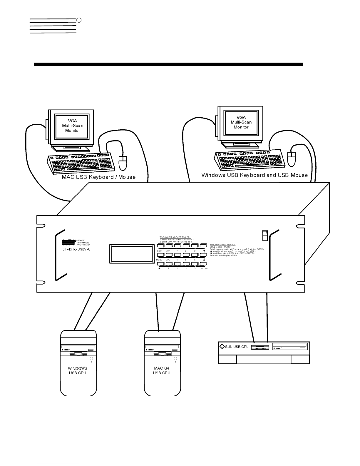
The NTI ST-nXm-USBV-U is a multi-user / USB KVM Switch, (n= number of users, m= number of CPUs). It allows multiple users
(up to 8), each with USB input devices and monitor, to communicate directly with any WINDOWS, MAC and/or SUN USB CPU (up
to 32) connected to the switch. These CPUs can be file servers, web servers, etc. The auto-boot circuitry in the ST-nXm-USBV-U
USB KVM switch allows all CPUs to boot simultaneously without keyboard and/or mouse error.
Definitions
• CPU
• Input Device
• System
• OSD
Enclosure that contains the operating system and processor
Keyboard or Mouse
One or more CPUs connected to one or more switches controlled by one or more input devices
On Screen Display
Limitations
• Only VGA multi-scan Monitors can be used with this product.
COMPATIBILITY
The ST-nXm-USBV-U USB KVM switch supports the following USB CPUs:
• Windows USB CPUs
• SUN (including all SUN Blades and SUN Rays) USB CPUs
• MAC USB CPUs
ORDERING INFORMATION
The ST-nXm-USBV-U USB KVM switch is built to a specific size ranging from 2 to 8 users and 8 to 32 CPUs. The s witch is built at
the factory based on the specified size ordered. The switch has USB inputs and outputs that support all platforms and are
configured with interface cables, see interface cable section. The “n” in the part number ST -nXm-USBV-U represents the number
of users. Select either 2, 4, or 8 user switches. The “m” in the part number represents the number of CPUs. The switch is
available with either 8, 16, 24, or 32 sets of CPU ports. It is not necessary to connect a user or CPU to each port (I.e. a ST-2x16
switch has the capability of supporting 16 CPUs, but can have only 10 CPUs connected and 6 unconnected ports.
ST-nXm-USBV-U
Replace the “n” with either 2, 4, or 8
Replace the “m” with either 8, 16, 24, or 32
The following list represents the available sizes that can be ordered:
ST-2x8-USBV-U ST-4X8-USBV-U ST-8X8-USBV-U
ST-2x16-USBV-U ST-4X16-USBV-U ST-8X16-USBV-U
ST-2X32-USBV-U ST-4X32-USBV-U ST-8X24-USBV-U
ST-8X32-USBV-U
1
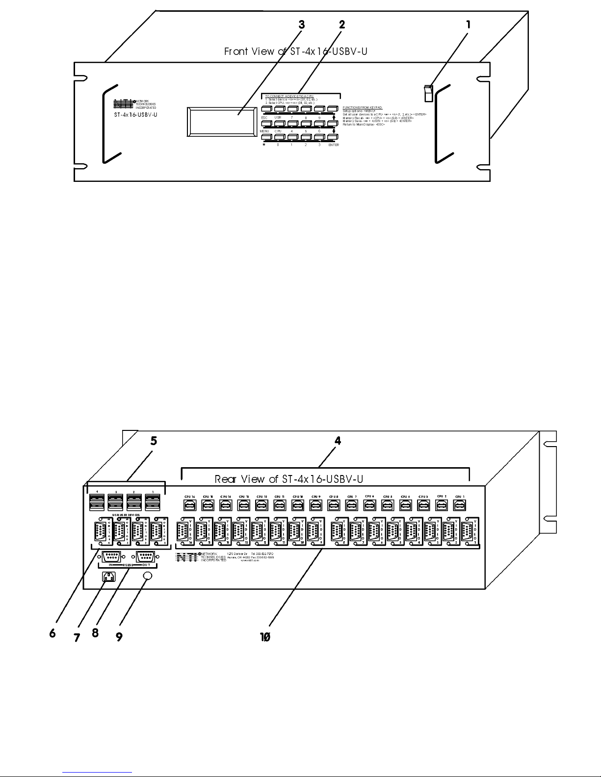
FEATURES AND FUNCTIONS
1. Power ON/OFF switch
2. Keypad- buttons for user control over switch functions
3. LCD Display- for visual indication of connection between the user and a specific CPU.
4. CPU x- USB Type B female connectors- for connection of CPU device cables
5. USB User Device x- USB Type A female connectors- for connection of user input device cables
6. Monitor x- 15HD female connectors- for connection of user monitors
7. IEC Power Connector- for attachment of power cord (not available on all units)
8. RS232 In/Out - for attaching RS232 interface cable from a CPU to control the functions of one or more
switches
9. Fuse Holder- holder for replaceable overcurrent protection fuse (not available on all units)
10. VIDEO x- 15HD female connectors- for attachment of video cables from CPUs
Additional Features
• A single CPU can be used by one or shared by several users.
• Any USB type input device can control any USB CPU (Windows, MAC, and SUN platforms).
• Power cycle circuit control allows the ST-nXm-USBV-U switch to be powered OFF, then ON, at any time without affecting the
attached CPUs. (This assumes that the CPU supports hot plugging.)
2

• Security features can be enabled on a user port by user port basis.
• A microprocessor is dedicated to each CPU, preventing connected CPUs from locking up.
• Any input device cable can be hot-plugged.
• Typically the LCD display indicates the CPU to which each user is connected.
• 10 configurations can be saved in memory by the user for instant setup recall.
• No dip-switches or jumpers necessary to configure.
• Video formats up to 1900X1200 can be displayed from all platforms. (A VGA multi-scan monitor must be used.)
• Users can control the switch using the On Screen Display (OSD):
• RS-232 control allows control of the switch with one CPU serial port. (Windows-based software is provided.)
• Matrix Switcher's Control Program provides easy and powerful graphical control of matrix switches through the RS-232
interface. (Windows only.)
Optional Features
• Dual redundant power supply.
MATERIALS
Materials Supplied with this kit:
• ST-nXm-USBV-U NTI Multi-user USB KVM Switch
Materials Not Supplied, but REQUIRED:
• USBVEXT-xx-MM cable for each CPU being connected to the switch
Where:
xx is the length of the cable in feet (3,6,10, or 15 feet available)
MM indicates male-to-male connector
Cables can be purchased from Network Technologies Inc by calling 800-RGB-TECH (800-742-8324) or 330-562-7070.
Options
The following options are available for the ST-nXm-USBV-U switch.
• Dual Redundant Power supply (see page 25)
This feature ensures constant power to the ST-nXm-USBV-U switch.
This feature is ordered by adding a -DRP suffix to the main part number.
3
INSTALLATION
It is not necessary to turn OFF power to CPUs or monitors during this installation unless RS-232 is going to be connected. All
cables, except for the RS-232 cables, may be hot plugged.
If using RS-232 Control see RS-232 section on page 21 for more information. Observe normal preca utions when connecting the
RS232 cables to the CPU. Refer to the owners manual for the CPU being connected for precautions, if any.
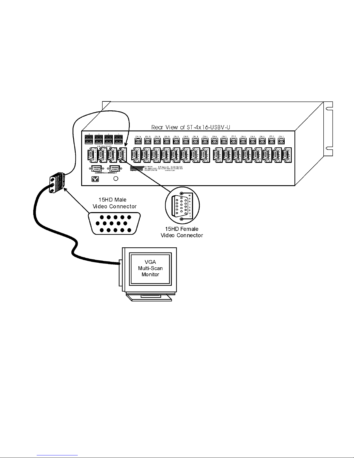
1. Connect the 15HD male cable end from each user monitor to the female 15HD ports labeled "MONITOR x " on the rear of the
ST-nXm-USBV-U switch. See Fig. 1.
Fig. 1
4
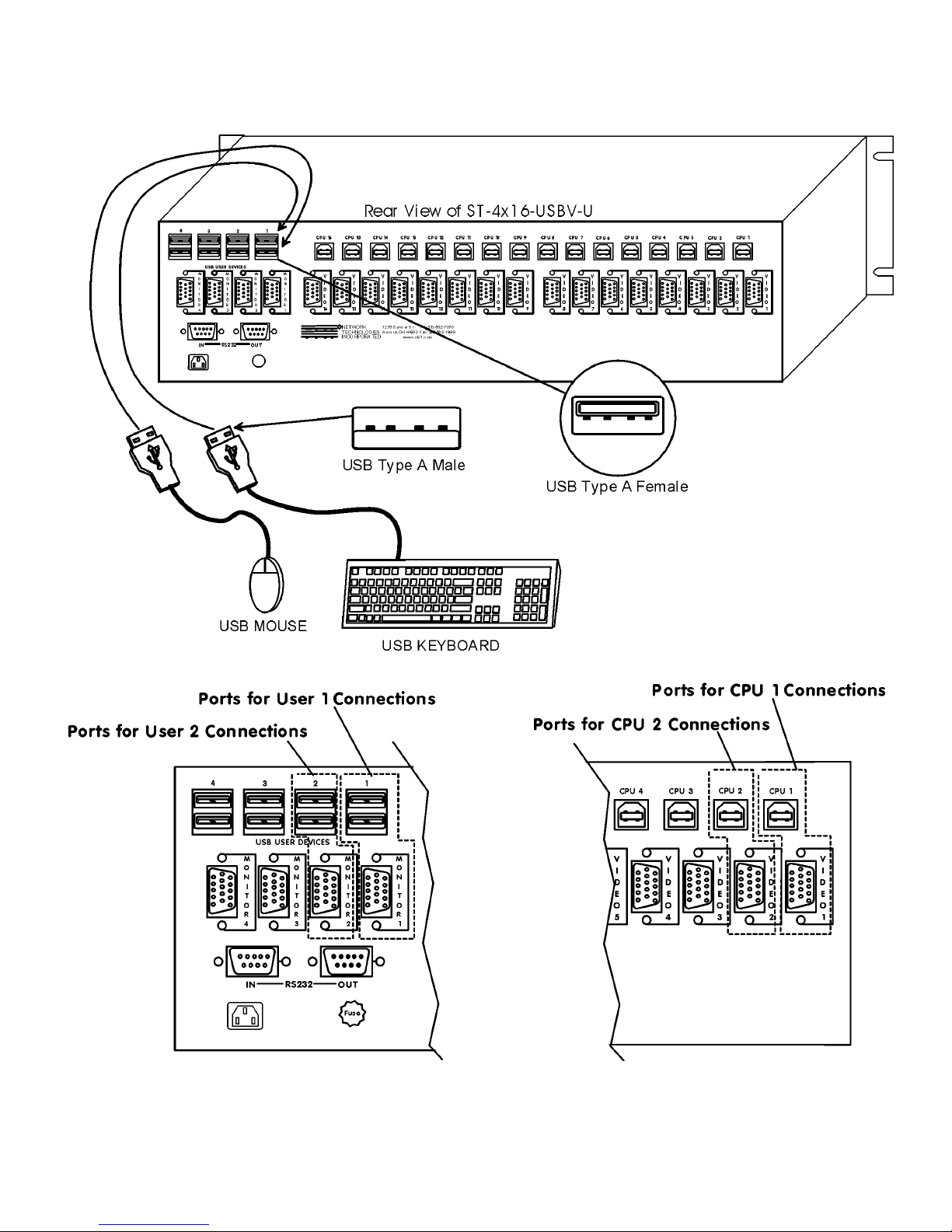
2. Connect the input devices to the USB type A female ports labeled USB USER DEVICES on the rear of the ST-nXm-USBV-U
switch. (See Fig. 2.) Ensure that the monitors and related input devices are connected to ports having the same port numbers.
(See Fig. 3.)
Fig. 2
Fig. 3 Fig. 4
5
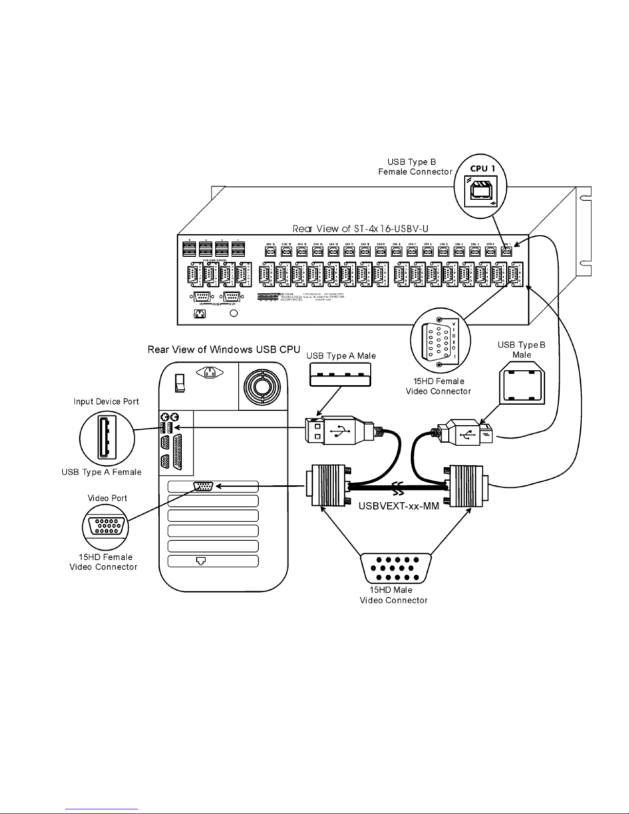
3. For each CPU:
• Connect a USB type A cable end of a USBVEXT-xxMM cable to a USB type A female input device port on a CPU.
Connect the USB type B cable end of the same cable to a CPU x port on the ST-nXm-USBV-U switch. Note the port’s
number. (See Fig. 3.)
• Connect the 15HD male cable ends of a USBVEXT-xx-MM cable from the video port of the same CPU to a VIDEO x port
of the ST-nXm-USBV-U switch with the same port number as the input device cable. (See Fig. 5.)
Note: Make sure the CPU is connected to a Keyboard port and a Video port with the same number. (See Fig. 4 on page 5.)
. Power-up
4
• Plug the ST-nXm-USBV-U switch into an AC power outlet.
• Turn ON power to the ST-nXm-USBV-U switch, the LCD should illuminate.
• Turn ON power to any or all CPUs connected to the ST-nXm-USBV-U switch (if they aren't ON already).
Note: The order in which the CPUs and switch are turned ON does not matter. A power strip can be used.
Fig. 5
6
USING THE NTI MULTI-USER USB KVM SWITCH
Basic Operation
The ST-nXm-USBV-U switch enables a user or several users (with sharin g enabled) to access any CPU at any time. A CPU can
be shared so that more than one user can use a CPU and work on the same project – each from their own cons ole. Resolution is
1900x1200 with no degradation – guaranteed. An LCD indicates the port to which each user is attach ed. The ST-nXm-USBV-U
can be controlled by three methods:
• keypad control with LCD via front panel
• OSD control via the user input devices
• RS-232 control
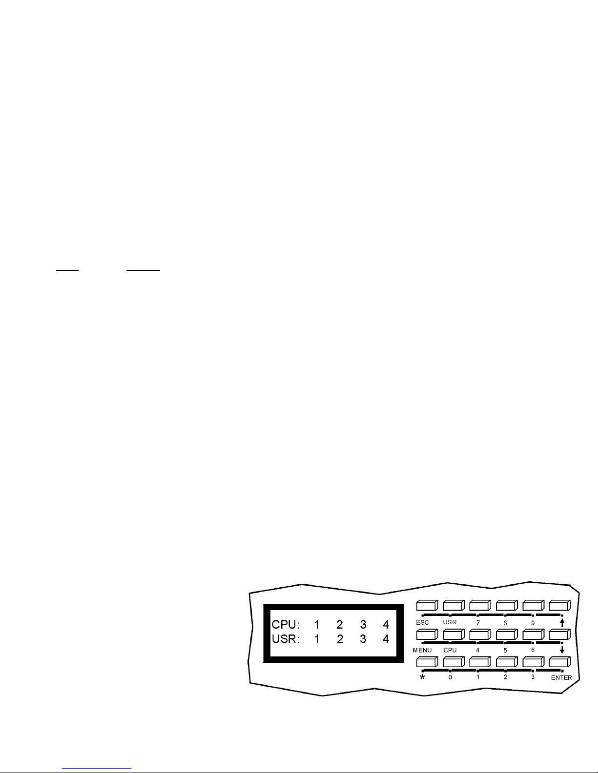
Keypad Control
The front panel keypad and LCD (see Fig. 6) display allo w the user to monitor switch status and route any user to any CPU on th e
switch. Along with the routing of the CPUs to the input devices the keypad and LCD allow the users to configure the RS-232
control interface. The keypad buttons perform the following functions:
Key Action
ESC Escape back to the main display.
0 – 9 Used to enter numbers. ( n )
USR The output user number can be entered (2 digits or 1 digit and ENTER)
followed by the desired CPU to be connected to.
CPU Used following single digit user entries.
ENTER Used following single digit entries.
Display next 4 users and the CPUs they are connected to.
Display previous 4 users and the CPUs they are connected to.
MENU The RS-232 menu is displayed. This allows the baud rate to be set at 9600, 2400, 1200 or 300 baud and the unit
address to be set to 1 - 15. See RS-232 control on page 21.
* Activate Memory Function- 10 memory locations (0 – 9), 0 is the power ON default.
to Save current connections
to Recall connections
Note: By default, the display will show all connections between CPUs and users, displaying 4 at a time, from the first to
the last, and repeating the cycle indefinitely. If the user presses either the up or down arrow to manually view
connections, the display will freeze on the chosen view. To resume the default cycle of displaying all connections, the
user must press and hold either the up or down arrow for 3 seconds, and then release it.
The following examples show various methods of routing user 3 to CPU 5. CPUs an d users can be entered as a t wo digit number
or a one digit number followed by ENTER.
USR - 3 - CPU - 5 - ENTER
USR - 3 - ENTER - 5 - ENTER
USR - 0 - 3 - 0 - 5
0 - 3 - 0 - 5
* - USR - n (0-9) - ENTER
* - CPU - n (0-9) - ENTER
Fig. 6
7
 Loading...