

NTI ST-nXm-U-HD Installation And Operation Manual
®
NODEMUX
HD Series
ST-nXm-U-HD
Multi-user / Universal KVM Switch
Installation and Operation Manual
MAN001 Rev Date 6/05/2006

TRADEMARK
NODEMUX is a registered trademark of Network Technologies Inc in the U.S. and other countries.
COPYRIGHT
Copyright © 2003, 2006 by Network Technologies Inc. All rights reserved. No part of this publication may be reproduced, stored
in a retrieval system, or transmitted, in any form or by any means, electronic, mechanical, photocopying, recording, or otherwise,
without the prior written consent of Network Technologies Inc, 1275 Danner Drive, Aurora, Ohio 44202.
CHANGES
The material in this guide is for information only and is subject to change without notice. Network Technologies Inc reserves the
right to make changes in the product design without reservation and without notification to its users.
CE Statement
We, Network Technologies Inc, declare under our sole responsibility that the NODEMUX HD Series switches described in this
manual are in conformity with European Standard EN5022.
i
MAN001 Rev Date 6/05/2006

TABLE OF CONTENTS
Introduction...................................................................................................................................................................... 1
Package Contents .......................................................................................................................................................1
Definitions ....................................................................................................................................................................1
Limitations.................................................................................................................................................................... 1
Compatibility ................................................................................................................................................................ 1
Ordering Information....................................................................................................................................................2
Interface Cables........................................................................................................................................................... 2
Features and Functions................................................................................................................................................... 3
Additional Features......................................................................................................................................................4
Installation ....................................................................................................................................................................... 5
Using the NODEMUX-HD Switch.................................................................................................................................... 7
Basic Operation ........................................................................................................................................................... 7
Keypad Control ............................................................................................................................................................ 7
OSD Control .................................................................................................................................................................... 9
Security Feature ..........................................................................................................................................................9
Enabling The Security Feature ................................................................................................................................. 9
Administrator Login ............................................................................................................................................ 9
User Login Mode.....................................................................................................................................................10
Additional OSD Modes Available With Security ........................................................................................................ 10
Administration Functions ........................................................................................................................................10
Administration Options ........................................................................................................................................10
Port Status Mode................................................................................................................................................. 11
Administrator Password................................................................................................................................... 11
User Name List.................................................................................................................................................... 12
System Access List ............................................................................................................................................. 12
User Access Functions.................................................................................................................................................. 13
Command Mode ........................................................................................................................................................13
Scan Mode................................................................................................................................................................. 15
Edit Mode................................................................................................................................................................... 16
Search Mode .............................................................................................................................................................16
Maintenance Mode ....................................................................................................................................................17
Keyboards ..................................................................................................................................................................... 19
Key Equivalents ......................................................................................................................................................... 19
SUN’s Startup Keys ................................................................................................................................................... 19
SUN’s 14 Extra Keys ................................................................................................................................................. 19
RS232 Control............................................................................................................................................................... 21
Remote Connection ..............................................................................................................
Baud Rate ............................................................................................................................................................... 21
Unit Address ...........................................................................................................................................................21
Command Protocol .................................................................................................................................................... 22
Autostatus............................................................................................................................................................22
RS232 Interface Test Program..................................................................................................................................23
Main Options...........................................................................................................................................................23
Matrix Options.........................................................................................................................................................23
Setup Options .........................................................................................................................................................23
Matrix Switcher's Control Program For Windows 9X, NT, 2000 and XP ......................................................................24
Safety and EMC Regulatory Statements ......................................................................................................................24
Technical Specifications................................................................................................................................................25
Troubleshooting............................................................................................................................................................. 26
Warranty Information.....................................................................................................................................................26
..................................... 21
ii
MAN001 Rev Date 6/05/2006

TABLE OF FIGURES
Figure 1- Connect devices to switch using interface cables...............................................................................................................5
Figure 2- Connect CPUs to switch using interface cables .................................................................................................................6
Figure 3- User login screen................................................................................................................................................................9
Figure 4- Administration Mode Menu...............................................................................................................................................11
Figure 5- Administrator password menu.....................................................................................................................................11
Figure 6- User Name List................................................................................................................................................................. 12
Figure 7- Command Mode main menu ............................................................................................................................................13
Figure 8- Maintenance Mode menu ................................................................................................................................................. 17
Figure 9- Keyboard Layouts.............................................................................................................................................................20
Figure 10- RS232 Connections for Daisy-chain...............................................................................................................................21
Appendices
Appendix A- Defaults ....................................................................................................................................................................... 25
Appendix B- General Information..................................................................................................................................................... 25
Appendix C- Cables.........................................................................................................................................................................25
Appendix D- Rack mounting Instructions ......................................................................................................................................... 26
iii
MAN001 Rev Date 6/05/2006

NTI NODEMUX HD Multi-user Universal KVM Switch
INTRODUCTION
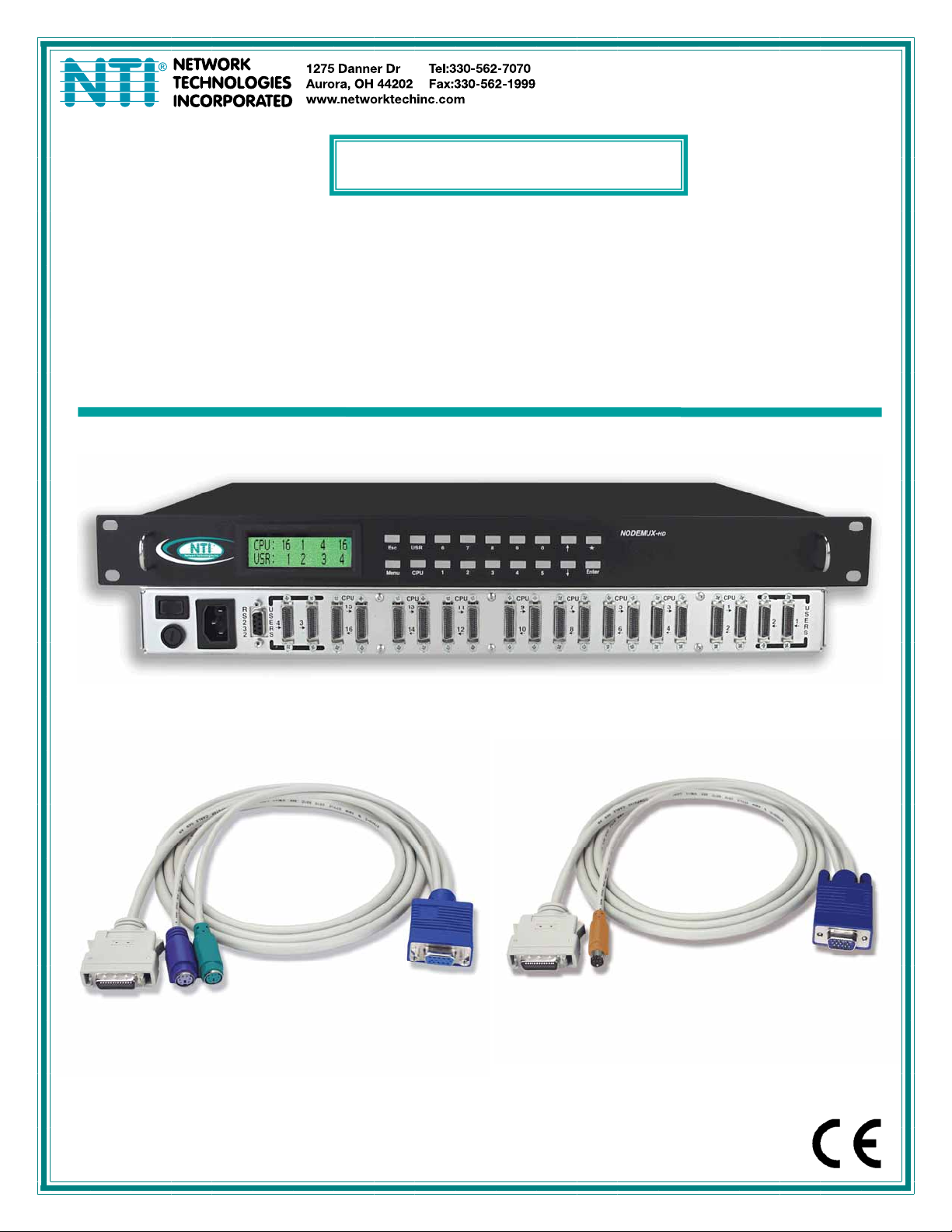
The NTI ST-nXm-U-HD (also known as NODEMUX-HD) is a multi-user / Universal Multi-Platform Matrix KVM switch, (n= number
of users, m= number of CPUs) with high density construction to require less rack space. It allows multiple users, up to 4, each
with a keyboard, monitor, and mouse, to communicate directly with any PS/2 or SUN workstation connected to the switch. A
single switch can connect to up to 16 CPUs. These CPUs can be file servers, network managers, etc. The auto-boot circuitry in
the NTI switch allows all CPUs to boot simultaneously without keyboard and/or mouse error. Resolution is supported through
1900x1200 with no degradation – guaranteed.
Package Contents
Materials Included with this kit:
9 NTI ST-nXm-U-HD Multi-User Universal KVM Switch
9 IEC Line Cord- country specific
9 CD with pdf file of this owner's manual
Definitions
• CPU
• User Device
• System
• OSD
Enclosure that contains the operating system and processor
Keyboard or Mouse
One or more CPUs connected to one or more switches controlled by one or more user devices
On Screen Display
Limitations
• Only VGA multi-scan monitors can be used with this product.
Compatibility
The ST-nXm-U-HD Universal Matrix KVM switch supports the following:
• Windows PS/2 CPUs
• SUN CPUs (including all SUN Ultras, SUN Blades and SUN Rays) (USB SUN CPU's need USB-SUN adapter)
• PS/2 laptops
• IntelliMouse
Note: The wheel on IntelliMouse is treated as the third button on Sun CPUs and treated as a wheel on PS/2 style CPUs.
1

NTI NODEMUX HD Multi-user Universal KVM Switch
Ordering Information
The ST-nXm-U-HD switch is built to a specific size ranging from 2 or 4 users and 8 or 16 CPUs. The switch is built at the factory
based on the specified size ordered. The switch has high density connectors (similar to SCSI) for inputs and outputs that support
PS/2 and SUN platforms and are configured with interface cables (see "Interface Cables" section below). The “n” in the part
number ST-nXm-U-HD represents the number of users. Select either 2 or 4 user switches. The “m” in the part number represents
the number of CPUs. The switch is available with either 8 or 16 CPU ports. It is not necessary to connect a user or CPU to each
port (ex. a ST-2x16 switch has the capability of supporting 16 CPUs, but can have only 10 CPUs connected and 6 empty ports.)
ST-nXm-U-HD
Replace the “n” with either 2 or 4
Replace the “m” with either 8 or 16
The following list represents the available sizes that can be ordered:
ST-2x8-U-HD ST-4X8-U-HD
ST-2x16-U-HD ST-4X16-U-HD
Interface Cables
Interface cables and adapters are not included and must be purchased separately.
A cable for each CPU being connected to the switch:
CPU to Switch
PS/2
CPU to Switch
SUN
• VMTINT-xx-MM for video, keyboard and mouse
OR
• SMTINT-xx-MM for video, keyboard and mouse
• 13W3M-15HDF (adapter for 13W3 to 15HD)
• USB-SUN Adapter (adapter for USB SUN CPU)
One of the following cables must be used to connect the keyboard/mouse and monitor:
PS/2
keyboard/mouse VMTINT-xx
OR
keyboard/mouse SMTINT-xx
SUN
where:
xx is the length of the cable in feet (3/6/10/15/25 foot cables available)
MM indicates male-to-male connector
Cables can be purchased from Network Technologies Inc by calling 800-RGB-TECH (800-742-8324) in the U.S. or (330) 5627070 worldwide.
interface
interface
2
NTI NODEMUX HD Multi-user Universal KVM Switch
6
7890
1 2 3
CPU
9
10
1
Front View of ST-4X16-U-HD
5
4
NODEMUX
*
ENTER
CPU
CPU
7
8
CPU
5
6
3
4
TM
HD
CPU
1
2
U
S
E
12
R
S
7
2
R
NTI
Network Technologies Inc
Rear View of ST-4X16-U-HD
CPU
U
R
S
S
E
2
4
R
3
S
2
56 7
4
3
15
3
16
CPU
13
14
CPU
USR
ESC
MENU
CPU
11
12
8
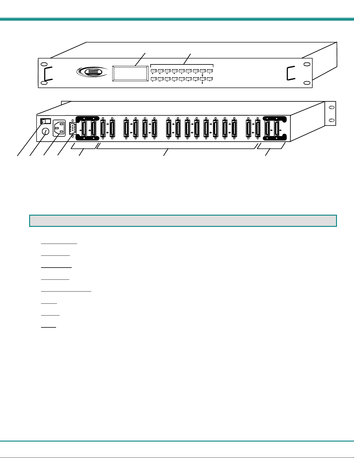
FEATURES AND FUNCTIONS
1. Keypad buttons- for user control over switch functions
2. LCD Display- for visual indication of connection between the user and a specific CPU.
3. Power switch- to power unit ON/OFF
4. Fuse Holder- for replaceable overcurrent protection fuse
5. IEC Power Connector
6. RS232
- 9D male connector- for attaching RS232 interface cable from a CPU to control the functions of one or more switches
7. USER x- high density female connectors- for connection of user device interface cables
8. CPU x -high density female connectors- for connection of CPU interface cables
- for attachment of country specific power cord
3

NTI NODEMUX HD Multi-user Universal KVM Switch
Additional Features
• Users can work individually or share the same CPU.
• Up to n users can work with m CPUs where n and m are the switch size acquired.
• High density (similar to SCSI) input and output ports that interface cables plug into adapt to PS/2 and SUN platform devices.
• Power cycle circuit control allows the NTI switch to be powered OFF, then ON, at any time without affecting the attached
CPUs.
• Power cycle circuit control allows the attached CPUs to be powered OFF, then ON, at any time without affecting the switch or
other attached CPU.
• OSD enabled system with security features optionally enabled on a port by port basis.
• A microprocessor is dedicated to each CPU, preventing connected CPUs from locking up.
• Each connected CPU can boot without a keyboard or mouse.
• Keyboard and mouse interface cable can be hot-plugged during operation.
• LCD display on the front panel shows the CPU to which each user is connected.
• 10 connection setups can be saved in memory by the user for instant setup recall.
• No dip switches or jumpers necessary to configure.
• Video formats up to 1900X1200 can be displayed from all platforms. (A VGA multi-scan monitor must be used)
• User’s keyboard and mouse can control the switch using the On Screen Display (OSD) of each user’s connections :
• Names can be assigned to the CPUs
• Password security on a port-enabled basis.
• RS-232 control allows control of the switch with one CPU serial port.
• Power required is 110 or 220 VAC @ 50-60 Hz at less than 50 watts.
4
NTI NODEMUX HD Multi-user Universal KVM Switch
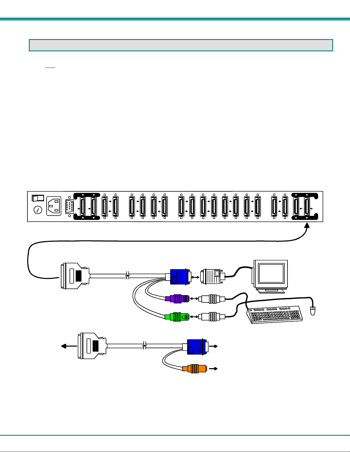
INSTALLATION
Turn OFF
cables.
1. If using RS-232 Control see RS-232 section (page 21) for more information.
2. Connect the monitors to the 15HD female connector ends of the VMTINT-xx or SMTINT-xx cables, depending upon what
3. Connect the keyboards to the purple 6 miniDIN female connector (PS/2) or orange 8 miniDIN female connector (SUN) of the
4. Connect the high density male connector end of the cable to a USER x port on the ST-nXm-U-HD switch.
NOTE: If it is desired for only a monitor to be connected to a user port, the device cable end(s) of the VMTINT-xx /
SMTINT-xx does not need to be connected to anything.
To USER x
port on
NODEMUX-HD
power to all CPUs that will be connected to the NTI NODEMUX-HD switch before connecting or disconnecting any
type of devices will be connected (PS/2 or SUN). See Fig. 1.
VMTINT-xx or SMTINT-xx (respectively). If using a PS/2 mouse, connect it to the green 6 miniDIN female connector on the
VMTINT-xx cable. See Fig. 1. Insure that the monitors and related keyboards are connected to the same interface cables.
Rear View of ST-4X16-U-HD
CPU
U
R
S
S
E
2
3
2
3
4
R
S
15
16
CPU
13
14
CPU
11
12
CPU
10
9
CPU
7
8
CPU
5
6
CPU
3
4
CPU
1
2
U
S
E
12
R
S
High Density
26 pin Male
VMTINT-3/6/10/15/25
High Density
26 pin Male
SMTINT-3/6/10/15/25
HD15-Female
(Dk Blue)
6mD-Female
(Purple-Keyboard)
6mD-Female
(Green-Mouse)
HD15-Female
(Dk Blue)
VGA
Multi-Scan
Monitor
PS/2 Keyboard
PS/2
Mouse
To a VGA
Multi-Scan
8mD-Female
(Light Orange)
Monitor
To a SUN
Keyboard/Mouse
Figure 1- Connect devices to switch using interface cables
5
 Loading...