

Page 1
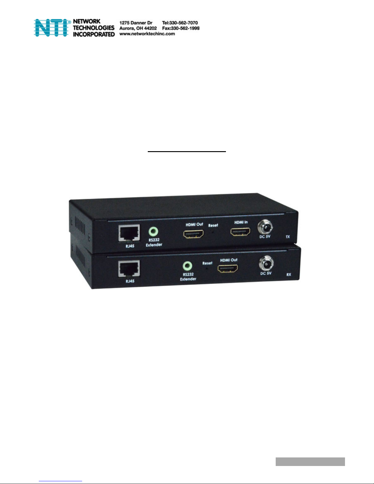
ST-IPHD-IR-LC
HDMI over Gigabit IP Extender
with IR and RS232
User Manual
Page 2

CONTENTS
1. Introduction
2. How It Connects
3. Features
4. Transmitter Unit Panel Layout
5. Transmitter Unit Panel Description
6. Receiver Unit Panel Layout
7. Receiver Unit Panel Description
8. Remote Control Panel Layout and Description
9. Connecting and Operating the Extender
10. Specification
Page 3

INTRODUCTION
The HDMI over IP Extender with LED extends HDMI signal over
just one 100 Ohm Cat.5e/Cat.6 cable -- up to 100 meters away.
The extender supports Full HD 1080p resolution. DVI-D Computer video
can also be transmitted with a DVI-to-HDMI cable or adaptor (Note: Audio
is not included in a DVI-D signal). Maximum screen resolution and
system performance is entirely dependent on the bandwidth and
features made available to the HDMI over IP Extender devices on the
local Gigabit network.
By using standard and widely available 100 Ohm Cat.6 cable, the
HDMI over IP Extender with LED makes HDMI signal networking
easier than larger, more expensive HDMI copper cable and more
robust than optical fiber cable.
Page 4

HOW IT CONNECTS
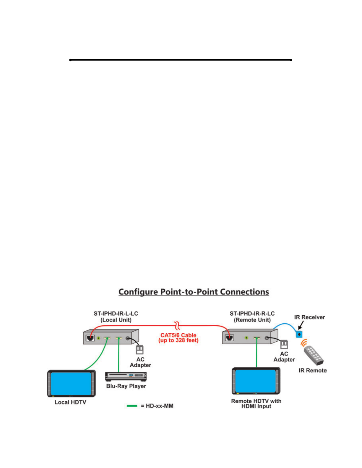
Point to Point
The HDMI over IP Extender with LED system consists of a
Transmitter and a Receiver (sold separately). The HDMI source
(set-top box, DVD/BluRay player, gaming console, etc.) connects to
the Transmitter unit. The Receiver unit connects to the HDTV display
in the same way. One 100 Ohm Cat5e/Cat.6 cable (up to 100 meters
long) links the Transmitter and Receiver. Power is applied to the
Transmitter and Receiver with 5V DC power supply (included). High
Definition picture and Sound are then transmitted into the HDTV
screen. HDMI Source Device can also be controlled remotely using
the built-in IR repeater in the System at the Receiver side.
Point to Multi-Point
The HDMI source connects to Transmitter unit via a high quality HDMI
cable. 100 Ohm Cat.5e/Cat.6 cables (each up to 100 meters in length)
link the Transmitter and Receivers via a Gigabit Full Duplex network
switch. The Receiver units connect to each of the HDTV displays via a
high quality HDMI cable. Power is applied to the Transmitters and
Receivers with 5V DC power supply (included). High Definition picture
and Sound are then transmitted into the HDTV screens, provided each
receiver unit which is set to the required source channel (remote
control supplied). HDMI Source Devices can also be controlled
remotely using the built in IR repeater in the HDMI over IP Extender
V2.0 with LED System at Receiver side.
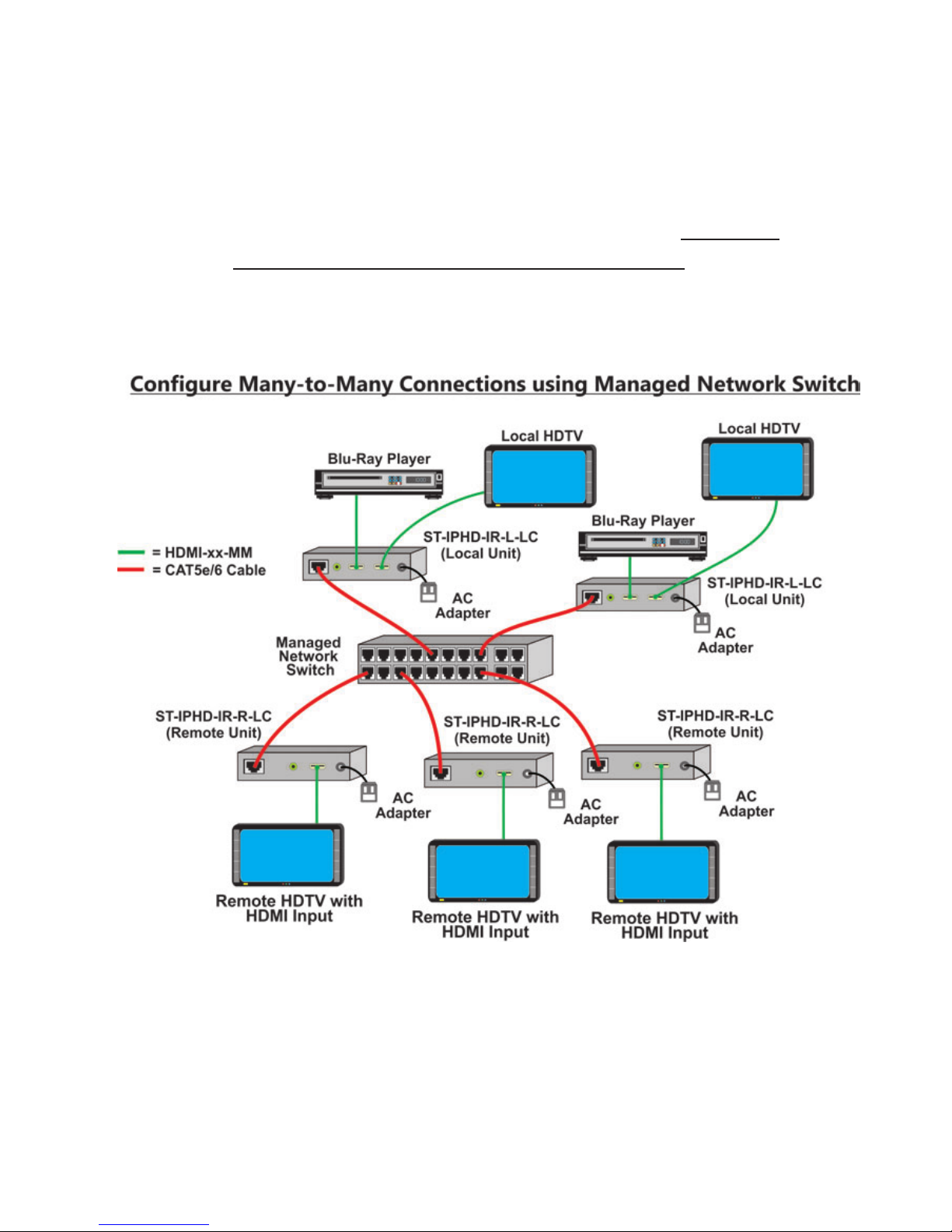
Multi-Point to Multi-Point
The HDMI source devices connect to each Transmitter unit (64 Max)
via a high quality HDMI cable. 100Ohm Cat.6 cables (each up to 100
meters in length) link the Transmitters and Receivers via a Gigabit Full
Duplex network switch that must support IGMP functionality. The
Receiver units connect to each of the HDTV displays via a high quality
HDMI cable. Power is applied to the Transmitters and Receivers with
5V DC power supply (included). High Definition picture and Sound are
then transmitted into the HDTV screens, provided each receiver unit is
set to the required source channel (remote control supplied). HDMI
Source Devices can also be controlled remotely using the built in IR
repeater in the HDMI over IP Extender with LED System at Receiver
side.
Note:ST-IPHD-IR-LC is HDCP 2.0 compliant.
Page 5

FEATURES
HDMI signal extension up to 100 meters
Supports HDTV resolution up to 1080p@60Hz
Supports PCM 2 Ch audio
Compliant with HDCP 2.0 standards
Audio and video are transmitted digitally over the 100 Ohm Cat.6 cable for
lower signal loss
Supports IR Pass thru function and control HDMI source devices (set-top
box, DVD player and Blue ray DVD Player) in Receiver by its IR remote
controller
It could control source channel from provided IR remote control, and LED
panel will show display source channel, which is easier for end user to
control.
Transmitter Package Includes
(1) 1x Transmitter
(2) 1x 5V DC Power Supply for Transmitter or Receiver
(3) 1x User Manual
(4) 1x RS232 Cable
Receiver Package Includes
(1) 1x Receiver
(2) 1x IR Receiver Cable
(3) 1x Remote Control
(4) 1x 5V DC Power Supply for Transmitter or Receiver
(5) 1x User Manual
(6) 1x RS232 Cable
Page 6
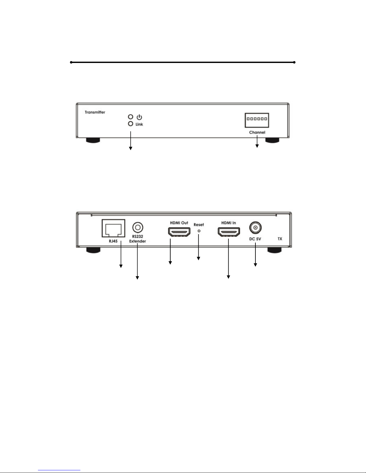
TRANSMITTER UNIT PANEL LAYOUT
Front Panel
Back Panel
Side Panel
Reset Button
RJ45 Port HDMI Output Port Power Input port
RS232 Extender Port HDMI Input Port
Power LED Dip Switch
Link LED
Page 7

TRANSMITTER UNIT PANEL DESCRIPTION
1. Power LED
This LED indicator will activate once the included 5V DC power
adapter has been properly connected between the Transmitter unit
and a power socket.
Note: the LED will blink during the initial power up time during which it
is loading the device firmware.
2. Link LED
This LED indicator will flash once Cat.6 cable has been properly
connected between the Transmitter and Receiver unit. Once both
devices are connected and powered up this LED will stop flashing
and stay on to indicate successful connection between Transmitter
and Receiver.
3. DIP Switch
It is possible (when network bandwidth allows) to have up to 64
transmitters and corresponding source devices running at once. The
DIP switch is designed to differentiate each transmitter unit and its
source device. System installers can change the combination of DIP
switch. If user differs DIP switch setting after system is set up, user
will need to reset the transmitter in order to let system identify new
source definition.
4. Power Input Port
Connect 5V DC power supply to this input port.
5. RJ45 Port
Connect a 100Ohm Cat.6 cable between this output port and the
RJ45 input port on Receiver unit or Gigabit network switch.
Note: for best performance we encourage the use of Stranded CAT6
shielded cable STP (750Mhz), as a minimum though please ensure
CAT6 UTP (550Mhz) cable is used or poor performance may result.
6. HDMI Input Port
Connect one HDMI cable between this port and HDMI output port of
the source device (DVD, Set-top box, blue-ray DVD)
7. HDMI Output Port
Connect on HDMI cable between this port and HDMI input port of the
display device can enable user to monitor the display from 100m
Page 8

away. The output from this port will be the same with the outpour from
receiver side.
8. RS232 Extender Port
Connect a serial communications port to this 3.5 mm connector for
bidirectional RS-232 communication.
Port Setup Parameters:
Baud Rate : 2400.
Data: 8bit.
Parity: none.
Stop:1bit.
Flow Control: none.
9. Reset
Occasionally like many network devices (routers, modems etc) it may
be necessary to reset the Transmitter. This can be done by using a
small tool (eg: toothpick) to gently press and hold the reset switch for
approximately 3 seconds. Upon releasing the switch the unit will
reboot and restore its factory settings. DIP switch settings will remain
as previously set and normal function should resume shortly.
Alternatively removing the Power Supply from the Power Input Port
for approximately 5 minutes will achieve the same result.
Page 9
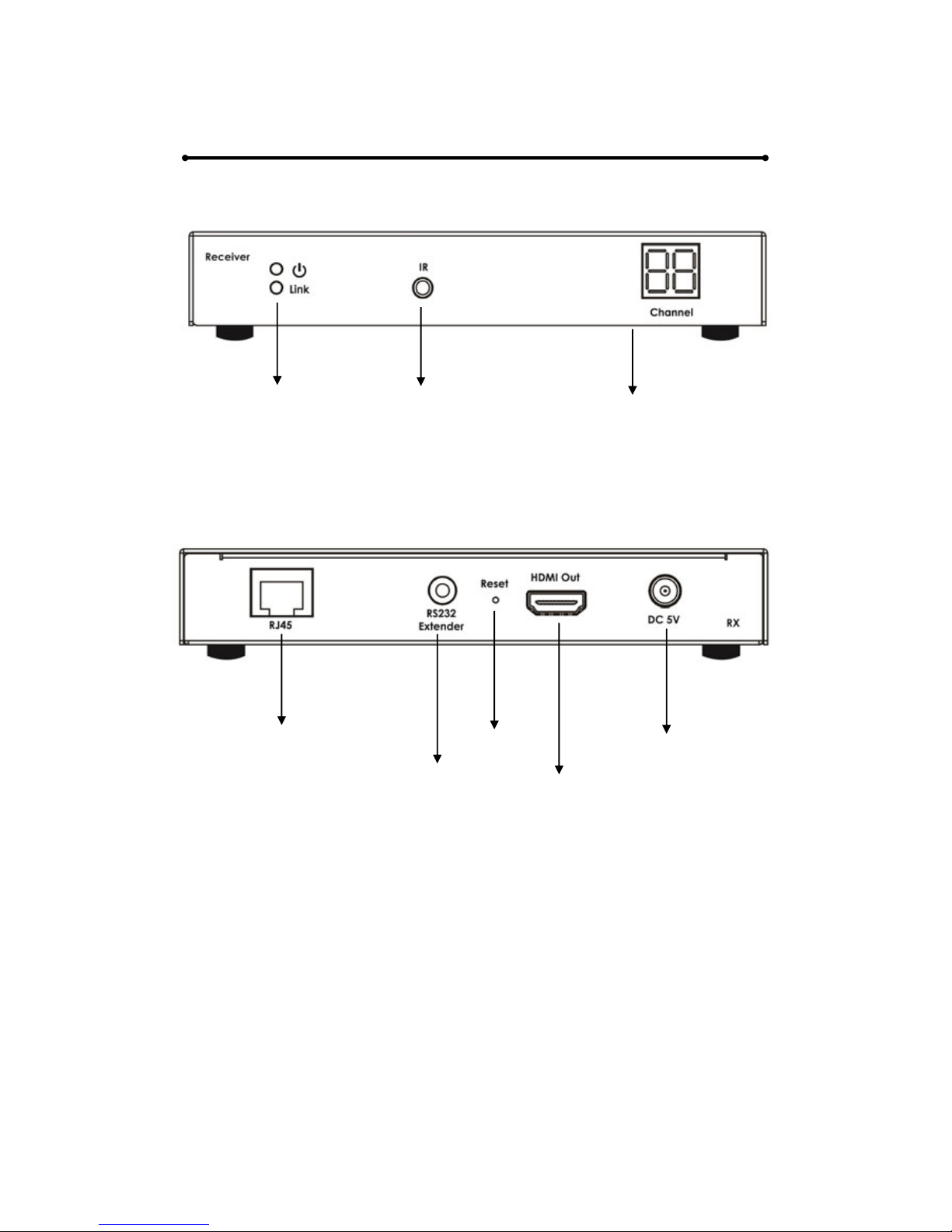
RECEIVER UNIT PANEL LAYOUT
Front Panel
Back Panel
Power LED IR Extender Port LED Display
Link LED
RJ45 Port Reset Button Power Input Port
RS232 Extender Port HDMI Output Port
Page 10

RECEIVER UNIT PANEL DESCRIPTION
1. Power LED
This LED indicator will activate once the included 5V DC power
adapter has been properly connected between the Transmitter unit
and a power socket.
Note: the LED will blink during the initial power up time during which it
is loading the device firmware.
2. Link LED
This LED indicator will flash once Cat 6. cable has been properly
connected between the Transmitter and Receiver unit. Once both
devices are connected and powered up this LED will stop flashing
and stay on to indicate successful connection between Transmitter
and Receiver.
3. IR Extender Port
Please connect the provided IR Extender cable to this port. This
allows the supplied remote control to function; the source device can
now also be controlled from the location of this receiver unit by way of
its original IR remote control or a universal type IR remote control.
4. LED Display
The LED Display is designed to identify which source device channel
the receiver is set to display. User can select source channel via the
provided remote control.
5. Power Input Port
Connect 5V DC power supply to this input port.
6. RJ45 Port
Connect a 100Ohm Cat.6 cable between this input port and the RJ45
output port from Transmitter unit or Gigabit network switch.
Note: for best performance we encourage the use of Stranded
CAT6A shielded cable STP (750Mhz), as a minimum though please
ensure CAT6 UTP (550Mhz) cable is used or poor performance may
result.
7. HDMI Output Port
Connect one HDMI cable between this output port and HDMI input
port of HDTV display.
Page 11

8. RS232 Extender Port
Connect a serial communications port to this 3.5 mm connector for
bidirectional RS-232 communication.
Port Setup Parameters:
Baud Rate : 2400.
Data: 8bit.
Parity: none.
Stop:1bit.
Flow Control: none.
9. Reset
Occasionally like many network devices (routers, modems etc) it may
be necessary to reset the Receiver. This can be done by using a
small tool (eg: toothpick) to gently press and hold the reset switch for
approximately 3 seconds. Upon releasing the switch the unit will
reboot and restore its factory settings. Source channel settings will
remain as previously set and normal function should resume shortly.
Alternatively removing the Power Supply from the Power Input Port
for approximately 5 minutes will achieve the same result.
Page 12
REMOTE CONTROL
PANEL LAYOUT & DISCRIPTION
Front Panel
1. Figure Keys : 0-9
The figure keys allows user to key in the source channel and shows
channel number on LED display of receiver. (It is ten-digit on LED
display, from CH00 – CH99, limitation depends on the quantity of
sources).
2. Upward Selection Button
This button allows user to switch to a higher source channel (from
source 00 to source 63). Hold this button down to change quickly.
3. Downward Selection Button
This button allows user to switch to a lower source channel (from
source 63 to source 00). Hold this button down to change quickly.
Press to switch
source channel
numerically
Press figure keys
to choose source
channel.
Page 13
CONNECTING AND OPERATING
How to Connect HDMI Over IP Extender with LED
One Source to One Display
1. Connect one HDMI Cable between the HDMI output port of source
device and the HDMI input port of Transmitter unit (5 Meters Max)
2. Connect one HDMI Cable between the HDMI input port of display
device and the HDMI output port of Receiver unit. (5 Meters Max)
3. Connect one 100 Ohm Cat.6 cable between the RJ45 port of
Transmitter unit and RJ45 port of Receiver unit.
Note: CAT.6 is to be no longer than 100 meters in length and should
not run parallel to mains power cables.
4. Connect 5V DC power supplies to both Transmitter and Receiver
unit.
5. Power on the display device first and then the source device.
6. Use the supplied remote control to select the related channels that
have been set to on the transmitters.
Note:
IR Function is able to receive signal from the IR remote control of
your source device and the remote control supplied with the
Receiver unit.
Page 14

CONNECTING AND OPERATING
How to Connect HDMI Over IP Extender with LED
One Source to Many Displays
1. Connect one HDMI Cable between the HDMI output port of source
device and the HDMI input port of Transmitter unit (5 Meters Max)
2. Connect one HDMI Cable between the HDMI input port of display
device and the HDMI output port of Receiver units. (5 Meters Max)
3. Connect one 100 Ohm Cat.6 cable between the RJ45 port of
transmitter and input port of a Full Duplex Gigabit Ethernet switch
(consult your network specialist for advice on choosing a suitable
Gigabit switch). Note: CAT.6 is to be no longer than 100 meters in
length and should not run parallel to mains power cables.
4. Connect one 100 Ohm Cat.6 cable between the output ports of the
Full Duplex Gigabit Ethernet switch and RJ45 port of each Receiver
unit. Note: CAT.6 is to be no longer than 100 meters in length and
should not run parallel to mains power cables.
5. Connect 5V DC power supplies to both Transmitter and Receiver
unit.
6. Power ON the Display device first and then the source device.
7. Use the supplied remote control to select the related channels that
the transmitters have been set to.
Note:
1. IR Function is able to receive signal from the IR remote control of
your source devices (or Universal Remote Control) and the
remote control supplied with the Receiver unit.
2. As the Transmitter units can support over 60,000 IP address for
different receiver units, it can connect up to 60,000 Receiver
units at once, this function, however, is completely limited by the
Gigabit LAN’s Bandwidth capacity. At times it may be necessary
to reduce the output resolution of your source devices to
compensate for lower than required bandwidth availability within
the network.
3. Please note that the Ethernet switch should be a Full Duplex
Gigabit Ethernet switch.
Page 15
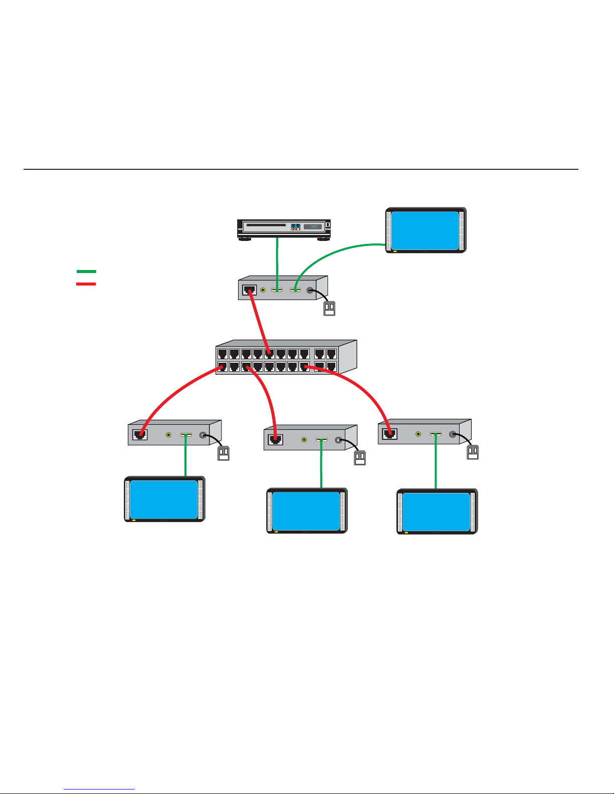
Configure Point-to-Many Connections using Un-Managed Network Switch
Local HDTV
Blu-Ray Player
= HDMI-xx-MM
= CAT5e/6 Cable
ST-IPHD-IR-R-LC
(Remote Unit)
Remote HDTV with
HDMI Input
Unmanaged
Network
Switch
ST-IPHD-IR-R-LC
(Remote Unit)
AC
Adapter
Remote HDTV with
HDMI Input
ST-IPHD-IR-L-LC
(Local Unit)
AC
Adapter
AC
Adapter
Remote HDTV with
ST-IPHD-IR-R-LC
(Remote Unit)
AC
Adapter
HDMI Input
Page 16

CONNECTING AND OPERATING
How to Connect HDMI Over IP Extender with LED
Many Sources to Many Displays
1. Connect one HDMI Cable between the HDMI output port of source
device and the HDMI input port of Transmitter unit (5 Meters Max)
2. Connect one HDMI Cable between the HDMI input port of display
device and the HDMI output port of Receiver unit. (5 Meters Max)
3. Connect one 100 Ohm Cat.6 cable between the RJ45 port of each
transmitter and the input ports of a Full Duplex Gigabit Ethernet
switch (consult your network specialist for advice on choosing a
suitable Gigabit switch). Note: CAT.6 is to be no longer than 100
meters in length and should not run parallel to mains power cables.
4. Connect one 100 Ohm Cat.6 cable between the output ports of the
Full Duplex Gigabit Ethernet switch and RJ45 port of each Receiver
unit. Note: CAT.6 is to be no longer than 100 meters in length and
should not run parallel to mains power cables.
5. Connect 5V DC power supplies to all Transmitter units and Receiver
units.
6. For each Transmitter, please use a different DIP switch combination to
differentiate its ID. User can connect at most 64 Transmitters to the
system as our DIP switch gives at most 64 combinations. After
setting up ID for each Transmitter, users can select the required
source device which is chosen to display on each screen by using
the supplied remote control with each Receiver unit to select the
associated channel.
Note.
1. IR Function is able to receive signal from the IR remote control of
your Source Device and the IR remote control Supplied with the
Receiver unit.
2. As the Transmitter units can support over 60,000 IP address for
different receiver units, it can connect up to 60,000 Receiver
units at once, this function however is completely limited by the
Gigabit LAN’s Bandwidth capacity. At times it may be necessary
Page 17
to reduce the output resolution of your source devices to
compensate for lower than required bandwidth availability within
the network.
3. Users can connect at most 64 Transmitters to the system.
4. Please note that the Ethernet switch should be a Full Duplex
Gigabit Ethernet switch that supports IGMP functions.
Page 18
SPECIFICATION
PERFORMANCE
HDTV Resolutions
480p, 720p, 1080i, 1080p
Color Depth
8 Bit
Audio Format
PCM 2 Ch audio
IR Range
30 kHz to 50 kHz
Maximum Cable Range
HDMI Input: 5 meters Max,
HDMI Outputs: 5 meters Max
Video Bandwidth
150MHz via LAN
Input Video Signal
3.3 Volts P-P
Input DDC Signal
5.0 Volts P-P
I/O CONNECTORS
Transmitter
Inputs
1 x HDMI-A 19PIN Socket
1 x 2.5mm DC Jack
1 x 3.5mm RS232 Extender
Outputs
1 x RJ45 Jack
1 x HDMI-A 19PIN Socket
Receiver
Inputs
1 x RJ45 Jack
1 x 2.5mm DC Jack
1 x 3.5mm RS232 Extender
Outputs
1 x HDMI-A 19PIN Socket
1 x 3.5 mm Jack - IR Receiver
MECHANICAL
Transmitter
Dimensions (H-W-D)
155x79x25mm
Weight
0.7kg
Receiver
Dimensions (H-W-D)
155x101.5x25mm
Weight
0.6kg
WARRANTY
Page 19
Limited Warranty
24 months
ENVIRONMENTAL
Operating Temperature
+0 to +40° C (+32° to 104° F)
Operating Humidity
10% to 85% (Non-condensing)
Storage Temperature
-20° to +60° (+20° to +140° F)
Storage Humidity
10% to 85% (Non-condensing)
POWER REQUIREMENTS
External Power Supply
SAFETY
Certificate
FCC, CE, RoHS
Power Adapter
UL, FCC, CE, RoHS
Page 20
Appendix 1.
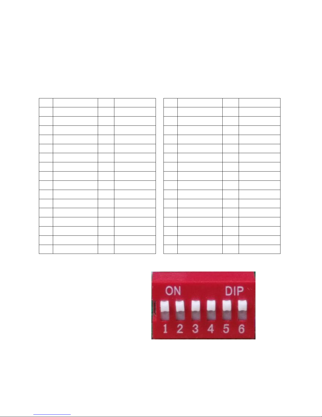
There are 64 combinations for the DIP switch, please refer to the following
table which defines 64 source channels for the Transmitter.
Note:
0 = ▽ Down
1 = △ Up
CH
Combination
CH
Combination
00
000000
16
000010
01
100000
17
100010
02
010000
18
010010
03
110000
19
110010
04
001000
20
001010
05
101000
21
101010
06
011000
22
011010
07
111000
23
111010
08
000100
24
000110
09
100100
25
100110
10
010100
26
010110
11
110100
27
110110
12
001100
28
001110
13
101100
29
101110
14
011100
30
011110
15
111100
31
111110
CH
Combination
CH
Combination
32
000001
48
000011
33
100001
49
100011
34
010001
50
010011
35
110001
51
110011
36
001001
52
001011
37
101001
53
101011
38
011001
54
011011
39
111001
55
111011
40
000101
56
000111
41
100101
57
100111
42
010101
58
010111
43
110101
59
110111
44
001101
60
001111
45
101101
61
101111
46
011101
62
011111
47
111101
63
111111
 Loading...