

XTENDEX
®
Series
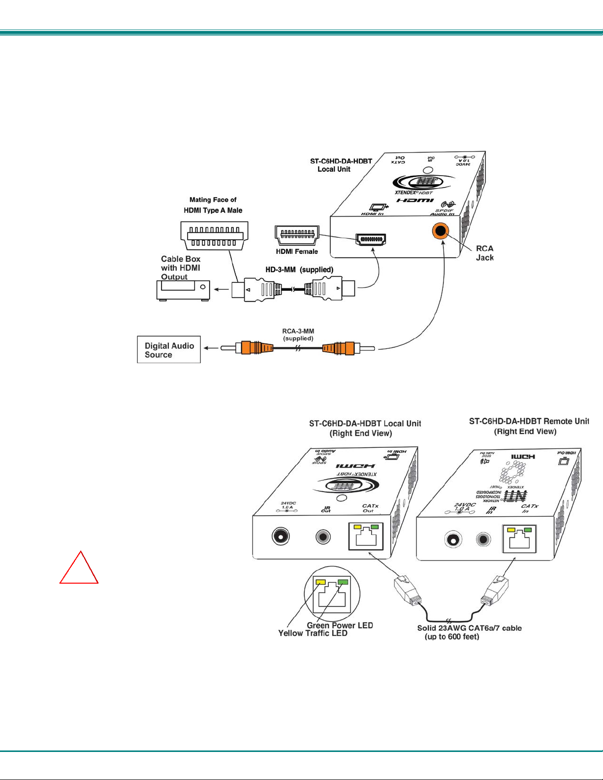
ST-C6HD-DA-HDBT Local Unit
(Left and Right End Views)
ST-C6HDE-HDBT Local Unit
(Left and Right End Views)
ST-C6HD-HDBT
ST-C6HD-DA-HDBT
ST-C6HD(A)E-HDBT
ST-C64K-300
HDMI, Digital/Stereo Audio, Ethernet, RS232
and IR Extender
Installation and Operation Manual
MAN150 Rev Date 10/30/2017

TRADEMARK
XTENDEX is a registered trademark of Network Technologies Inc in the U.S. and other countries.
COPYRIGHT
Copyright © 2008,2017 by Network T echnologies Inc. All rights reserved. No part of this publication may be reproduc ed, stored
in a retrieval system, or transmitted, in any form or by any means, electronic, mechanical, photocopying, recording, or otherwise,
without the prior written consent of Network Technologies Inc, 1275 Danner Drive, Aurora, Ohio 44202.
CHANGES
The material in this guide is for information only and is subject to change without notice. Network Technologies Inc reserves the
right to make changes in the product des ign without reservation and without notification to its users.
Note: CATx connection cable used between NTI XTENDEX Series Local and Remote or any XTENDEX Series products
should not be run underground, outdoors or between buildings.
WARNING: Outdoor or underground runs of CATx cable could be dangerous and will void the warranty.
WARNING: The CATx connection cable used between NTI XTENDEX Series Local and Remote or any XTENDEX Series
products must be wired straight through (pin 1 to pin 1, pin 2 to pin 2, etc.) The use of a CROSSOVER CABLE will
damage the extender and void your warranty.
i

TABLE OF CONTENTS
Introduction ...................................................................................................................................................................... 1
Materials .......................................................................................................................................................................... 2
Connectors and LEDs ..................................................................................................................................................... 4
Limitations ....................................................................................................................................................................... 6
Preparation for Installation .............................................................................................................................................. 6
Installation ....................................................................................................................................................................... 7
Installing The Remote Unit .......................................................................................................................................... 7
Installing The Local Unit .............................................................................................................................................. 8
Connect the CATx Cables ........................................................................................................................................... 8
Plug-in and Boot Up ................................................................................................................................................... 10
Infrared Control ............................................................................................................................................................. 11
100BaseT + RS232 Support ......................................................................................................................................... 12
Technical Specifications ................................................................................................................................................ 13
Interconnection Cable Wiring Method ........................................................................................................................... 14
Troubleshooting ............................................................................................................................................................. 15
Warranty Information ..................................................................................................................................................... 15
TABLE OF FIGURES
Figure 1- Connect the extended components to the Remote Unit ..................................................................................................... 7
Figure 2- Installation with DVI-only monitor ....................................................................................................................................... 7
Figure 3- Connect the XTENDEX Local Unit to the source ................................................................................................................ 8
Figure 4- Connect CATx cable ........................................................................................................................................................... 8
Figure 5- Connect the AC adapter to either the Remote Unit or the Local Unit ............................................................................... 10
Figure 6- Connect IR Emitter and Receiver ..................................................................................................................................... 11
Figure 7- Connections for Ethernet and RS232 Support.................................................................................................................. 12
Figure 8- View looking into RJ45 fem ale.......................................................................................................................................... 14
ii

NTI XTENDEX 600 Foot HDMI and IR Extender
INTRODUCTION
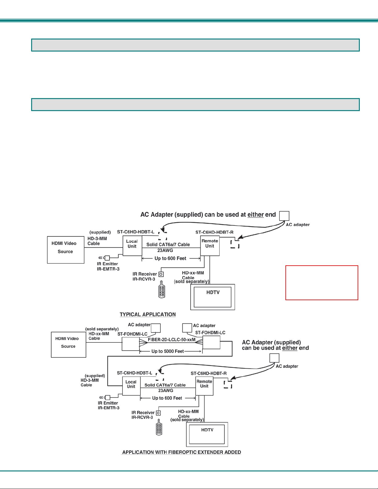
The XTENDEX Series ST-C6HD-HDBT HDMI HDBase-T Extender transmits uncompressed digital HDMI signal, IR , and optional
SPDIF digital audio up to 600 feet over a single CAT6a/7 23AWG cable (o r up to 450 feet with solid CAT5e/6) usi ng HDBase-T
technology. Each video extender consists of a local unit that connects t o an HDMI source and IR emitter; and a remote unit that
connects to an HDMI display, IR receiver, and optional SPDIF speakers .
The XTENDEX Series ST-C64K-300 4K HDMI Extender transmits uncompressed digital HDMI signal, and IR up to 300 feet over a
single CATx solid wire cable. Each video extender consists of a local unit that connects to an HDMI source and IR emitter; and a
remote unit that connects to an HDMI display and IR receiver.
The XTENDEX Series Extender is extremely simple to install and has been thoroughly tested to insure reliab le performance.
Through the use of CAT5e/6/6a/7 (CATx) cable it is possible to economically increase the flexibility of an entertainment system.
Here are some of the features and ways this can benefit you:
ST-C6HD-HDBT Features:
• Transmits an uncompressed high speed HDMI s i gnal over one CATx cable.
• Supports HDTV resolutions to 1080p and video resolutions to 1920x1200.
o Extend 1080p up to 5,600 feet when combined with NTI's ST-FOHDMI-LC HDMI Extender via Fiber Optic
Cable.
• HDMI features supported:
o 1920x1200 resolution
o x.v.Color, sYCC601 color, Adobe RGB Color and Adobe YCC601 color
o Dolby TrueHD, DTS-HD Master Audio, Dolby Di gi tal, and DTS
o Bandwidth up to 154 MHz (3.76Gbps)
o Support for CEC (consumer electronic control) compatible devices.
o Lip Sync
• HDCP compliant.
• Supports the DDC2B protocol.
• High quality, rugged steel construction with durable powder coat finish.
• Only one power supply is necessary. (Power supply can be connected to either the local or remote unit.)
• Full Infrared Remote (IR) control of HDMI source from remote HDTV using existi ng source remote control.
Options:
Available with optional SPDIF Digital Audio support. (order ST-C6HD-DA-HDBT)
Available with optional SPDIF Di gital Audio and Stereo Audio support ( order ST-C6HDA-HDBT)
Available with Ethernet port for 100BaseT ext ension to support a Local or Wide Area Network (LAN/WAN) connection + an
RS232 port for serial devices such as Touch Screen monitors (order ST-C6HDE-HDBT).
Available with “12VDC 2A” power rating ( order ST-C6HD-HDBT-12VNPS)- 2.1 x 5.5mm power jack, AC adapter sold separately
1
NTI XTENDEX 600 Foot HDMI and IR Extender
ST-C64K-300 Features:
• Transmits an uncompressed high speed HDMI signal over one CATx cable.
• Supports Ultra HD 4Kx2K resolutions to 3840x2160(30Hz) 2K resolutions to 2048x1080, HDTV resolutions to 108 0p and
computer resolutions to 1920x1200.
• Supports embedded digital audio through HDMI compatible TV’s or audio receivers.
• HDMI features supported:
o HDMI 1.4
o x.v.Color, sYCC601 color, Adobe RGB Color and Adobe YCC601 color
o Dolby TrueHD, DTS-HD Master Audio, Dolby Di gi tal, and DTS
o Bandwidth up to 340MHz (10.2Gbps)
o Support for CEC (consumer electronic control) compatible devices.
o Lip Sync
• HDCP compliant.
• Supports the DDC2B protocol.
• High quality, rugged steel const ruction with durable powder coat finish.
• Only one power supply is necessary. (Power supply can be connected to either the local or remote unit.)
• Full Infrared Remote (IR) control of HDMI source from remote HDTV using existi ng source remote control.
MATERIALS
Materials Included with ST-C6HD-HDBT/ST-C64K-300 kit:
NTI XTENDEX Local Unit
NTI XTENDEX Remote Unit
1-HD-3-MM 3 foot male-to-male HDMI video cable
1-RCA-3-MM 3 foot male-to-male RCA cable (ST-C6HD-DA-HDBT and ST-C6HDA(E)-HDBT models only)
1- SA-3-MM 3 foot male-to-male 3.5mm stereo audio c able (ST-C6HDA(E)-HDBT models only)
1-100VAC to 240VAC at 50 or 60Hz-24VDC/1.0A AC Adapter (NTI#PS4202) (NOT included with ST-C6HD-HDBT-12VNPS)
1- Power Cord- country specific (NOT included with ST -C6HD-HDBT-12VNPS)
3 Foot IR-EMITTER (IR-EMTR-3)
3 Foot IR-RECEIVER (IR-RCVR-3)
2.1x.5.5mm DC Plug with 36” Lead (ST-C6HD-HDBT-12VNPS only)
Additional Materials Included with ST-C6HDE-HDBT kit:
CT6182 DB9 Female-to-RJ45 Female adapter
CT6488 DB9 Male-to-RJ45 Female adapter
2-CB4352 5 foot RJ45-to-RJ45 CAT5 patch cable
Additional materials may be required but are not supplied:
CAT5e solid UTP ; 6/6a solid UTP; CAT6a solid UTP 23A WG; /CAT7 solid STP 23AWG (CATx) twisted-pair cables
terminated with RJ45 connectors wired straight thru- pin 1 to pin 1, etc. (see page 14 for proper EIA/TIA 568 B wiring method)
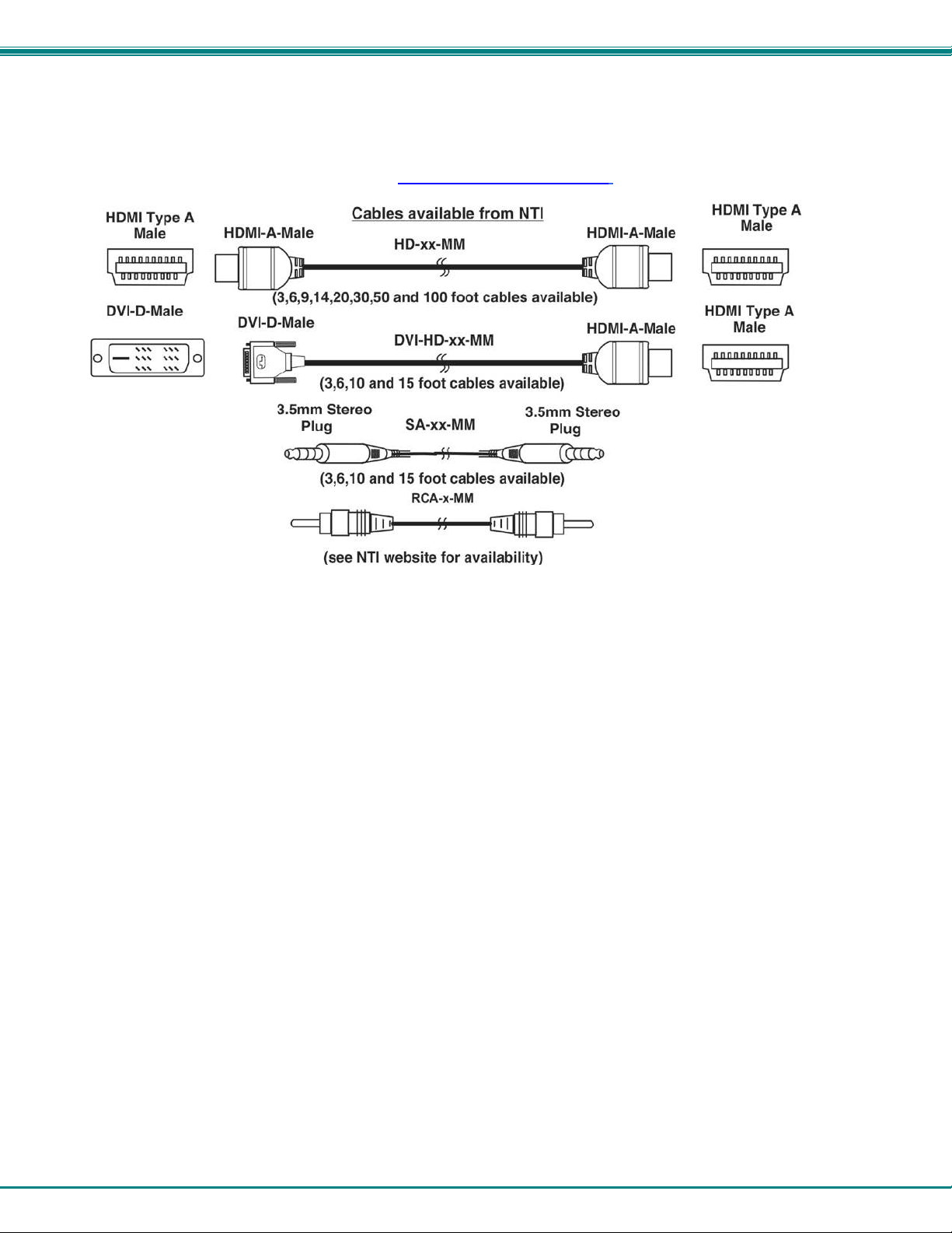
HDMI male-male cable to connect a HDMI source or display (Order NTI # HD-xx-MM where xx=3, 6, 9,14,20, 30, 50 and 100
foot cable).
DVI-D male to HDMI-A male single link cable t o connect a DVI source or display (Order NTI # DVI-HD-xx-MM where xx=3, 6,
10, or 15 foot cable)
2
NTI XTENDEX 600 Foot HDMI and IR Extender
RCA male-male cable to connect the SPDIF digit al audio (when supported) t o an audio output device (Order NTI # RCA-x-
MM – see website for available lengths)
Always use the shortest possible cab le for best performance.
Contact your nearest NTI distributor or N TI directly for all of your KVM nee ds at 800-RGB-TECH (800-742-8324) in US & C anada
or 330-562-7070 (Worldwide) or at our website at http://www.networktechinc.com and we will be happy to be of ass istance.
3
NTI XTENDEX 600 Foot HDMI and IR Extender
#
LABEL
CONNECTOR
DESCRIPTION
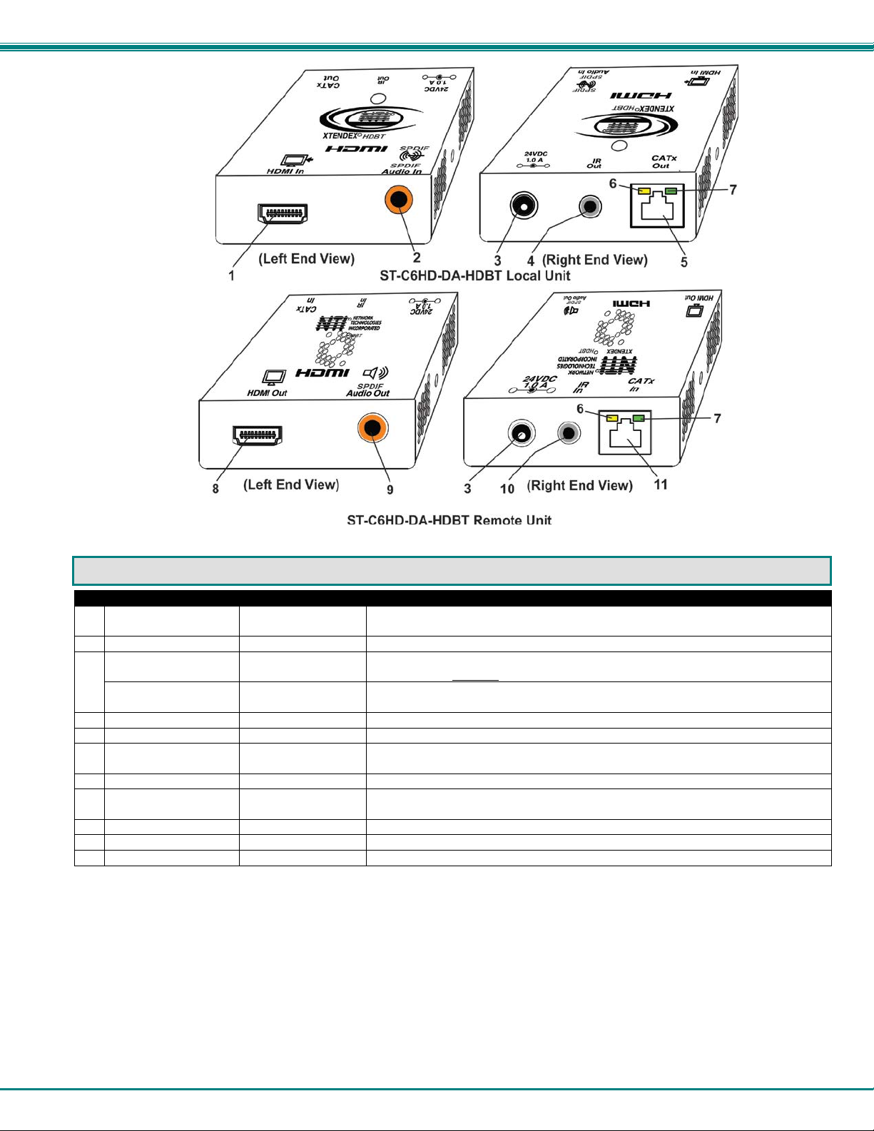
1
HDMI In
HDMI female video
connector
for connecting an HDMI cable between the Local Unit and the video source
2
SPDIF Audio In
RCA Jack
For connecting SPDIF digital audio source (ST-C6HD-DA-HDBT only)
3 24VDC- 1.0A
1.0mm Power Jack
connection jack for the AC adapter (on ly the Local or the Remote Unit needs to
be powered, not both) (Not applicable to ST-C6HD-HDBT-12VNPS)
12VDC- 2.0A
2.1X5.5mm Power
Jack
connection jack for the 12V AC adapter (only the Local Unit) (ST-C6HDHDBT-12VNPS model only)
4
IR Out
3.5mm Stereo Jack
for connecting the IR Emitter
5
CATx Out
RJ45 connector
for connecting the CAT5e/6/6a/7 cable between the Local and Remote units
6
Yellow LED
--
traffic indicator- illuminates when there is communication between the local
and remote units.
7
Green LED
--
power indicator- illuminates when power has been supplied to the unit
8
HDMI Out
HDMI female video
connector
for connecting the remote display dev i c e
9
SPDIF Audio Out
RCA Jack
For connecting SPDIF digital audio device (ST-C6HD-DA-HDBT only)
10
IR In
3.5mm Stereo Jack
for connecting the IR Receiver
11
CATx In
RJ45 connector
for connecting the CAT5e/6/6a/7 cable between the Local and Remote units
CONNECTORS AN D LEDS
Note: ST-C64K-300 has same connections as ST-C6HD-HDBT (above). (SPDIF Audio is not supported)
4

NTI XTENDEX 600 Foot HDMI and IR Extender
#
LABEL
CONNECTOR
DESCRIPTION
1
HDMI In
HDMI female video
connector
for connecting an HDMI cable between the Local Unit and the video source
3 24VDC- 1.0A
1.0mm Power Jack
connection jack for the AC adapter (on ly the Local or the Remote Unit needs to
be powered, not both)
4
IR Out
3.5mm Stereo Jack
for connecting the IR Emitter
5
CATx Out
RJ45 connector
for connecting the CAT5e/6/6a/7 cable between the Local and Remote units
6
Yellow LED
--
traffic indicator- illuminates when there is communication between the local
and remote units.
7
Green LED
--
power indicator- illuminates when power has been supplied to the unit
8
HDMI Out
HDMI female video
connector
for connecting the remote display dev i c e
10
IR In
3.5mm Stereo Jack
for connecting the IR Receiver
11
CATx In
RJ45 connector
for connecting the CAT5e/6/6a/7 cable between the Local and Remote units
12
Ground
Ground terminal
for connecting external ground wire
13
Ethernet
RJ45 connector
for connecting cable to either the LAN or an extended Ethernet connected
device (model with 100BaseT support only)
14
RS232 (DTE)
RJ45 connector
for connecting serial cable to touchscreen monitor
15
RS232 (DCE)
RJ45 connector
for connecting serial cable from CP U
16
SPDIF Audio In
RCA connector
for connecting SPDIF digital audio source
17
Stereo Audio In
3.5mm Jack
for connecting stereo audio source
18
SPDIF Audio Out
RCA connector
for connecting SPDIF digital speaker system
19
Stereo Audio Out
3.5mm Jack
for connecting stereo speakers
CONNECTORS AN D LEDS
WARNING: If the CATx IN or CATx OUT ports of a powered Remote o r Local extender are connected to th e R S 232 port of
another Remote or Local unit, the CATx port will be damaged and render the XTENDEX unusable and void the warranty.
5
NTI XTENDEX 600 Foot HDMI and IR Extender
12V model is powered
LIMITATIONS
• The use of CAT5e or of any stranded cabling will re duce the maximum distance and resolut ion.
WARNING: If the CATx IN or CATx OUT ports of a powered Remote or Local extender are connected to the RS232 port of
another Remote or Local unit, the CATx port will be damaged and render the XTENDEX unusable and void the warranty.
PREPARATION FOR INSTALLATION
• Locations should be chosen for the monitor that also has space to connect the Remote unit within the distance provid ed by
the cables. If extension cables are needed, contact NTI for the cables requir ed.
• The CATx cables must be run to the locations where the Remote and Local units will be connected. Be careful to route the
cables away from any sources of m agnetic fields or electrical interference that might reduce the quality of the video signal
(i.e. AC motors, welding equipment, fluoresc ent lighting, etc.).
• All cables should be installed in such a way t hat they do not cause stress on their connec tions to the equipment. Extended
lengths of cable hanging from a connect ion may interfere with the quality of that connection. Secure cables as needed to
minimize this.
• Properly shut down and disconnect the power from the video source and monitor to be separated. If other equipment is
involved whose connections are being interrupted, be sure to refer t o the instruction manuals for that equipment for proper
disconnection and reconnection pr ocedures before proceeding.
• Be very careful not to obstruct the air vents on the Remote Unit in its installed locati on.
at the Local Unit only.
Power supply sold
separately.
6

NTI XTENDEX 600 Foot HDMI and IR Extender
INSTALLATION
Installing The Remote Unit
1. Position the Remote Unit such that the CATx cable, the monitor cable(s), and audio cables (if applicable) can each
reach the Remote Unit without put ting strain on the cables.
2. Connect a HD-xx-MM (or DVI-HD-xx-MM cable depending upon what connector your display will accept) t o the
female HDMI video connector labeled " HDMI Out" on the Remote Unit.
3. Connect the RCA cable (optional) between the audio device and the “SPDIF A udi o Out” on the Remote Unit.
Note: The audio signal will be present at the “SPDIF Audio Out” connector if an audio source is connected to the “SPDIF
Audio In” connector on the Local Unit.
Note: Be very careful that the installed location does not obstruct the air vents in Remote Unit case.
Figure 1- Connect the extended components to the Remote Unit
Figure 2- Installation with DVI-only monitor
7
NTI XTENDEX 600 Foot HDMI and IR Extender
!
Installing The Local Unit
1. Connect an HD-3-MM (supplied) or DVI-HD-xx-MM cable (page 3) between the video source and the " HDMI In" connector on
the Local Unit.
2. Connect a RCA-3-MM (supplied) between an aud i o out port on the audio source and the “ SPDIF Audio In” connector on the
Local Unit (model ST-C6HD-DA-HDBT only).
Figure 3- Connect the XTENDEX Local Unit to the source
Connect the CATx Cables
Connect the CATx cable between t he “CATx”
ports on the Local and Remote Unit. (S ee
Figure 4) When properly inserted the cable
ends should snap into place.
Note: The ST-C64K-300 can be connected
with a maximum 300 foot cable (CAT6a/ 7
STP).
WARNING: Never connect the
XTENDEX to an Ethernet card, Ethernet
router, hub or switch or other Ethernet
RJ45 connector of an Ethernet device.
Damage to devices connected to the
Ethernet may result.
Figure 4- Connect CATx cable
WARNING: The CATx connection cab le used between NTI XTENDEX Series Local and Remote or any XTENDEX Series
products must be wired straight through (pin 1 to pin 1, pin 2 to pin 2, etc.) The use of a CROSSOVER CABLE will
damage the extender and void your warranty.
8

NTI XTENDEX 600 Foot HDMI and IR Extender
SPDIF and Stereo Audio Feature
Models ST-C6HDA(E)-HDBT include extra ports to support the connection of a separate audio source if desired. Either a SPDIF
digital audio source OR a stereo audi o source can be connected (not both
the Remote Unit through digital speakers and/or self-powered stereo are connected to it.
) to the Local Unit. The audio source will be heard at
Figure 5- Connect an audio source to the Local Unit
Figure 6- Connect SPDIF Digital and/or Stereo Speakers
9

NTI XTENDEX 600 Foot HDMI and IR Extender
The AC adapter can be
XTENDEX function
Plug-in and Boot Up
1. Plug the power cord from the monitor into the power outlet .
2. Connect an AC adapter power connector to the 24VDC port on either the Remote Unit or the Local Unit. Plug t he A C
adapter into a power outlet. The gr een LE D on the RJ45 connector of both the Rem ote and Local Units should illumi nate,
indicating that a proper power connection has been made to them. (See
3. Turn ON the video source and monitor. The yellow LED on both t he Local and Remote Units should illu minate. The video
source and monitor should each reac t as if directly connected to each other.
NOTE: The ST-C6HD-HDBT-12VNPS is powered by a 12VDC 2A power supply (sold separately) and at t he Local Unit
only. The Remote Unit is powered by the Local Unit through the CATx cable.
connected to either the
Local Unit OR the
Remote Unit to make the
Figure 7)
Figure 7- Connect the AC adapter to either the Remote Unit or the Local Unit
10

NTI XTENDEX 600 Foot HDMI and IR Extender
3.5MM Mono Plug
IR Emitter
3.5MM Stereo Plug
IR Receiv er
IR-RCVR-3
IR-EMTR-3
Note: The IR Emitter and Receiver work within a frequency range of 30-50kHz. Check the
INFRARED CONTROL
The XTENDEX includes ports for connec ting an infrared emitter and receiver (included) to work in conjunction with the IR remote
control used to operate the signal source. Connect the receiver to the “IR IN” port on the Remote Unit and the emitter t o the “IR
OUT” port on the Local unit. Position t he end of the receiver such that the signal fr om the remote control can easily reach the IR
sensor. Position the end of the emitter such that the extended signal can be sent t o the signal source.
specifications for the device you are extending to make sure the XTENDEX will work with it.
Figure 8- Connect IR Emitter and Receiver
11
NTI XTENDEX 600 Foot HDMI and IR Extender
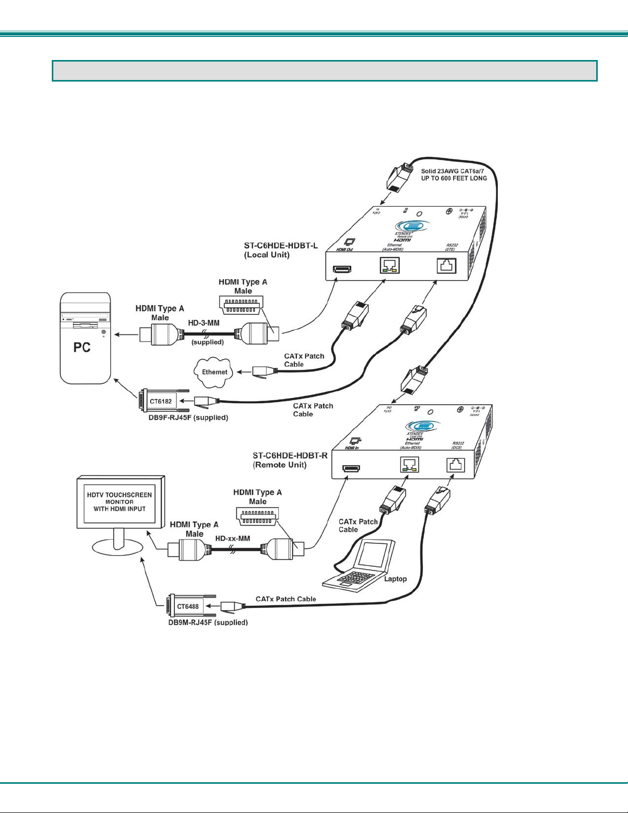
100BASET + RS232 SUPPORT
If you have purchased the STC6HDE-HDBT, then your unit includes additional support for 100BaseT and RS232 extension.
With the 100BaseT support option, the “Ethernet Port” can be used to extend a Loc al or Wide Area Network (LAN/WAN)
connection. The Local or Remote unit c an be used to connect a modem, Blu-Ray player, router or switch or a network device
(PC, printer, hub etc) If the net work device is connected at the Local Unit , then the LAN/WAN connection must be at the Remote
Unit, and visa versa.
Figure 9- Connections for Ethernet and RS232 Support
Additionally, RS232 extension provides support for serial device communication, like touchscreen m oni tors as shown in the
figure above.
• Connect the DB9F to RJ45 adapter (su pplied) to the CPU and a CATx patch cable b etween the adapter and the “RS232”
port on the Local Unit.
• Connect the DB9M to RJ45 adapter (supplied) to the monitor and a CATx patch c able between the adapter and the
“RS232” port on the Remote Unit.
WARNING: If the CATx IN or CATx OUT ports of a powered Remote or Local extender are connected to the RS232 port of
another Remote or Local unit, the CATx port will be damaged and render the XTENDEX unusable and void the warranty.
12
NTI XTENDEX 600 Foot HDMI and IR Extender
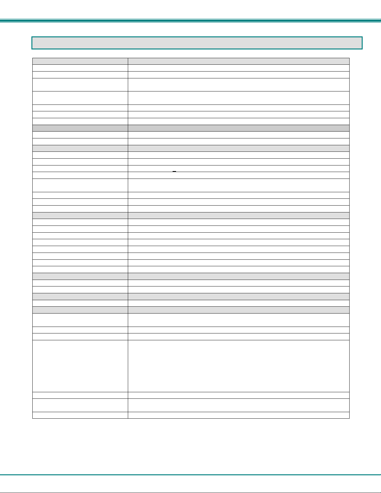
Video
Video Connectors
HDMI Type A Female
Input Video Signal
TMDS
Bandwidth
340MHz (10.2Gbps) (ST-C64K-300 model only)
154 MHz (3.76Gbps) (All other models )
HDMI Version
HDMI1.4 (ST-C64K-300 model only)
HDMI 1.2 (All other models)
DVI Support
DVI 1.0
DDC Support
DDC2b
HDCP Version
HDCP 1.2
Digital Audio (where supported)
Audio Connectors
RCA phono plug
Audio Format (SPDIF)
LPCM,Dolby Digital (AC3)(Plus),DTS,DSD, Dolby TrueHD,DTS-HD Master Audio
Stereo Audio (where supported)
Audio Connectors
3.5mm stereo jacks
Signal Type
Line Level, stereo, unbalanced
Audio Frequency Response
20Hz to 20Khz, + 1dB
Signal-to-noise ratio
-85 dB
Total Harmonic Distortion and
Noise
0.05%
Stereo Crosstalk
-80 dB
Audio Maximum I/O Levels
2V RMS input 1V RMS output
Output Impedance
Max 20 Ohms, unbalanced
IR
Input/Output
3.5mm Stereo Jack
Signal Type
TTL, 0-5VDC
Input Impedance
1.5 kohm
Output Impedance
33 ohm
Maximum Input/Output Level
5.0 Vp-p
Center Carrier Frequency
36kHz
Frequency Range
30-50kHz
Maximum Distance (from receiver)
10 feet, straight; 5 feet at 45 degree angle
Ethernet (where supported)
Input/Output
RJ45 Female
Speed
100BaseT
RS232 (where supported)
Input/Output
RJ45 Female
General
Interconnect Cable
CAT5e solid UTP/STP; CAT 6/6a Solid UTP/STP; CAT7 Solid STP EIA/TIA 568 B
wiring with male RJ45 connect or s (see table page 14)
Operating Temperature
0-50º C
Operating Humidity Range
17 to 90% non-condensing RH
Power
ST-C6HD(-DA)-HDBT- 100V to 240VAC at 50 or 60Hz-24VDC/1.0A via AC Adapter
(for Remote or Local, not both)
Enclosure type
Electro-galvanized steel black powder coated
Size (In.) WxDxH
2.54x3.08x1.08 (ST-C6HD-(DA)-HDBT and ST-C64K-300)
6.06x3.05x1.08 (ST-C6HD(AE)-HDBT only)
Compliance Certifications
CE, RoHS
TECHNICAL SPECIFICATIONS
(Included) (for Remote or Local, not both)
ST-C6HD(AE)-HDBT- 100V to 240VAC at 50 or 60Hz-24VDC/1.0A via AC Adapter
(Included) (for Remote or Local, not both)
ST-C6HD-HDBT-12VNPS- 12VDC/ 2.0A via AC Adapter (sold separately) (Local Unit
only)
ST-C64K-300- 100V to 240VAC at 50 or 60Hz-24VDC/1.0A via AC Adapter (Included)
13
NTI XTENDEX 600 Foot HDMI and IR Extender
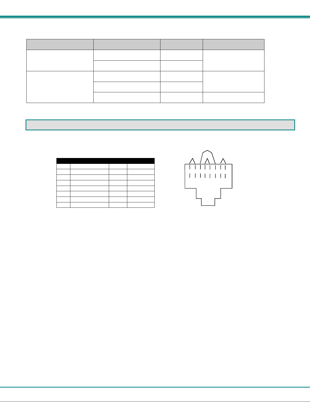
Cable Length
(In Feet)
Pin
Wire Color
Pair
Function
1 White/Orange
2 T 2 Orange 2 R
3 White/Green
3
T
4 Blue 1 R
5 White/Blue
1
T
6 Green 3 R
7 White/Brown
4 T 8 Brown 4 R
T
1
+
R
2
-
T
3
+
R
4
-
T
5
+
R
6
-
T
7
+
R
8
-
Pair 2 Pair 1
Pair 4
Pair 3
Cable Ranges Tested
Model Cable Type
Resolution
ST-C6HD(AE)-HDBT CAT5e/6 450 1900x1200, 1080p@60Hz
CAT6a/7 23AWG 600
ST-C64K-300 CAT5e/6 Solid UTP 150 3840x2160 @30Hz
CAT5e/6 Solid STP 250
CAT6a/7 Solid STP 300 3840x2160 @30Hz
INTERCONNECTION CABLE WIRING MET HOD
The CATx connection cables between the Remote and Local are terminated with RJ45 connectors and must be wired according
to the EIA/TIA 568 B industry standar d. Wiring is per the table and drawing below.
Figure 10- View looking into RJ45 female
14

NTI XTENDEX 600 Foot HDMI and IR Extender
Problem
Cause
Solution
Power LED does not
• Power supply is not connected or
• Make sure outlet is live and AC adapter is plugg ed-in.
Power LED illuminates
other
• CATx cable not properly
• Check the CATx cable connection at both en ds.
No Video on monitor
• One or more video cables is loose
• HDMI/DVI cable is too long
• Check all video cable connections
Video Picture is noisy
• All Video Cables are not firmly
• Check all connections. Make sure all cables are fully
Monitor flashes or goes
• Electrical power system is very
• HDMI/DVI cable is too long
• Make sure the interconnection cable is not near any
• Switch to shorter cable
TROUBLESHOOTING
Each and every piece of every product pro duced by Network Technologie s Inc is 100% tested to exacting specificat i ons. We
make every effort to insure trouble-free installation and operation of our products. If problems are experienced while installing this
product, please look over the troubleshooting chart below to see if perhaps we can answer any questions that aris e. If the
answer is not found in the chart, a solution may be found in the knowledgebase on our website at
http://information.networktechinc.com/jive/kbindex.jspa or please call us dir ec tly at (800) 742-8324 (800-RGB-TECH) or (330)
562-7070 and we will be happy to assist i n any way we can.
illuminate
on one end, and not the
plugged-in.
connected
or disconnected.
• No power to Remote Unit.
• CATx cable is not connected.
• CATx cable is too long
seated.
• CATx /HDMI/DVI cable is too long
• The CATx cable is not properly
connected.
• CATx cable is poor quality for the
length of cable used
• CATx cable is installed near noisy
equipment
• Make sure 24VDC jack is fully connected
• Make sure “Power” LED is illuminated on local and
remote. If not, see solutions for first problem above.
• With all the cables properly connected, power cycle the
video/audio source. Make sure “Traffic” LED on local
and remote is illuminated.
• Make sure they are snapped-in properly and completely
and reboot.
• Switch to shorter cable or lower resolution
seated.
• Switch to shorter cable or lower resolution
• Check cable connections. Make sure they are snapped-
in properly and completely.
• Install a higher quality CATx cable.
• Relocate run of CATx cable away from other electrical
equipment
blank for a second or two
WARNING: If the CATx IN or CATx OUT ports of a powered Remote or Local extender are connected to the RS232 port of
another Remote or Local unit, the CATx port will be damaged and render the XTENDEX unusable and void the warranty.
noisy, particularly the ground.
• The CATx cable is not properly
connected.
• CATx cable is too long
WARRANTY INFORMATION
The warranty period on this product (parts and labor) is two (2) years from the date of purchase. Please contact Network
Technologies Inc at (800) 742-8324 (800-RGB-TECH) or (330) 562-7070 or visit our website at
http://www.networktechinc.com/return-policy.html for information regarding repairs and/or returns . A return authorization number
is required for all repairs/returns.
WARNING: The CATx connection cab le used between NTI XTENDEX Series Local and Remote or any XTENDEX Series
products must be wired straight through (pin 1 to pin 1, pin 2 to pin 2, etc.) The use of a CROSSOVER CABLE will
damage the extender and void your warranty.
Manual 150 Rev. 10/30/17
power lines.
• Check cable connections. Make sure ends ar e s napped-
in properly and completely.
• Switch to shorter cable or lower resolution (maximum
length is 600 feet).
15
 Loading...