

NTI ST-C5V-600, VOPEX-M12V-4, ST-C5VA-600, ST-C5KVMRS-600, ST-C5VRS-600 Installation And Operation Manual
NTI
NETWORK
R
TECHNOLOGIES
INCORPORATED
1275 Danner Dr
Aurora, OH 44202
www.networktechinc.com
Tel:330-562-7070
Fax:330-562-1999
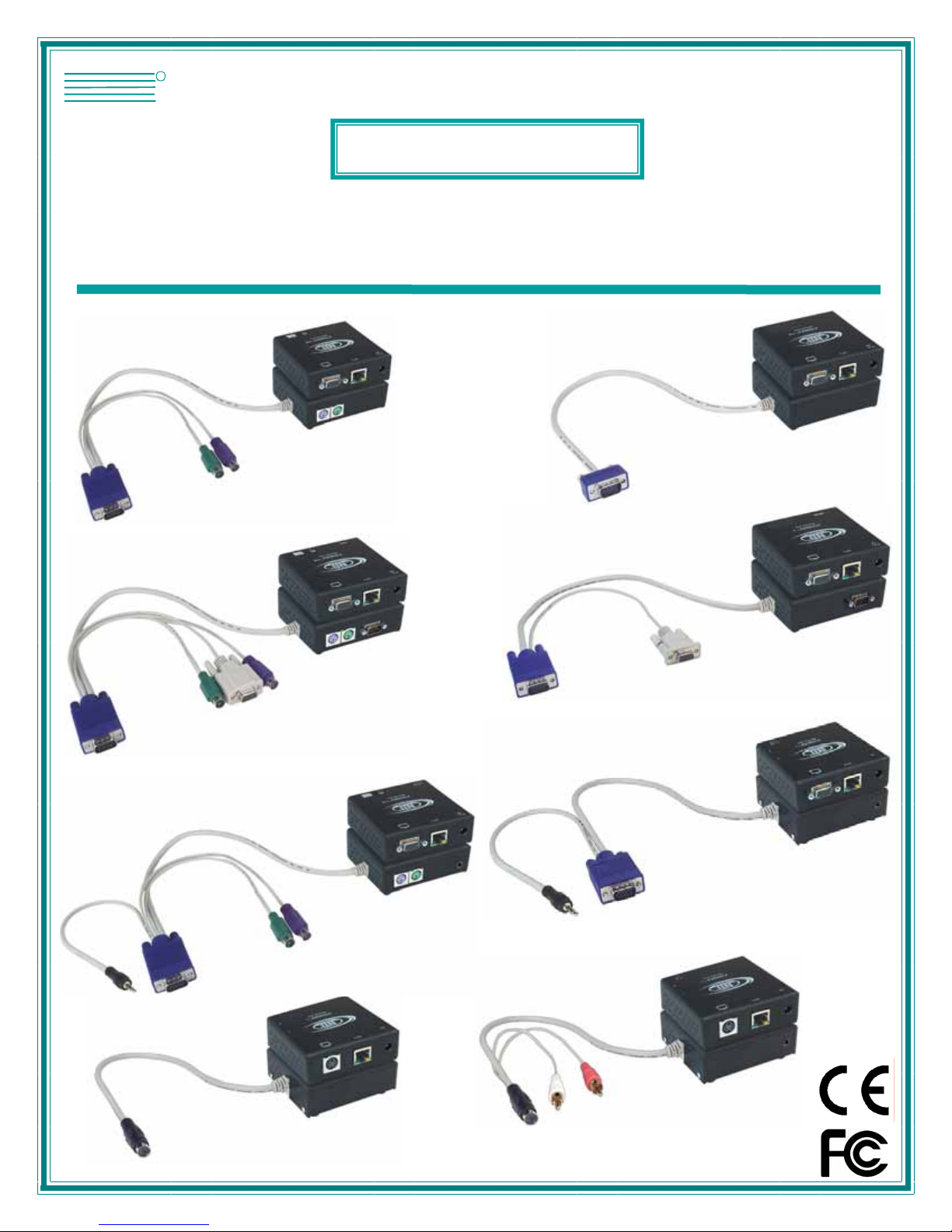
XTENDEX®Series
EXTENDERS
Installation and Operation Manual
ST-C5KVM-600
PS/2 KVM Extender
ST-C5KVMRS-600
PS/2 KVM and RS232
ST-C5SV-600
S-Video Extender
ST-C5KVMA-600
PS/2 KVM and Audio
ST-C5SV-600
S-Video Extender
ST-C5SVA-600
S-Video and
Audio Extender
ST-C5VA-600
Video and Audio
ST-C5V-600
Video Extender
ST-C5VRS-600
Video and RS232
Man014 Rev. 8/2/07

TRADEMARK
XTENDEX is a registered trademark of Network Technologies Inc in the U.S. and other countries.
COPYRIGHT
Copyright © 2003-2007 by Network Technologies Inc. All rights reserved. No part of this publication may be reproduced, stored
in a retrieval system, or transmitted, in any form or by any means, electronic, mechanical, photocopying, recording, or otherwise,
without the prior written consent of Network Technologies Inc, 1275 Danner Drive, Aurora, Ohio 44202.
CHANGES
The material in this guide is for information only and is subject to change without notice. Network Technologies Inc reserves the
right to make changes in the product design without reservation and without notification to its users.
Note: Shielded
CAT 5,5e, or 6 cable must be used to connect to LOCAL and REMOTE units in order to meet CE emission
and immunity requirements.
Note: CAT5 connection cable used between NTI XTENDEX Series Local and Remote or any XTENDEX Series products
should not be run underground, outdoors or between buildings.
WARNING: Outdoor or underground runs of CAT5 cable could be dangerous and will void the warranty.
CE Statement
We, Network Technologies Inc, declare under our sole responsibility that the ST-C5KVM-600, STC5KVMRS-600, STC5VMA-600,
ST-C5V-600, STC5VRS-600, ST-C5VA-600, ST-C5SV-600, and ST-C5SVA-600 is in conformity with European Standard
EN55022.
Federal Communications Commission Radio Frequency Interference Statement
This device complies with Part 15 of the FCC rules. Operation is subject to the following two conditions:
(1) This device may not cause harmful interference and
(2) this device must accept any interference received, including interference that might cause undesired operation.
This device complies with Part 15 of the FCC rules. This equipment has been tested and found to comply with the limits for a
Class A digital device, pursuant to Part 15 of the FCC rules. These limits are designed to provide reasonable protection against
harmful interference when the equipment is operated in a commercial environment.
Warning: This equipment generates, uses and can radiate radio frequen cy energy, and, if not installed and used in
accordance with the instruction manual, may cause harmful interference to radio communications.
i
Man014 Rev. 8/2/07

TABLE OF CONTENTS
Introduction......................................................................................................................................................................1
Materials..........................................................................................................................................................................2
Features and Functions...................................................................................................................................................3
Limitations .......................................................................................................................................................................5
Preparation for Installation ..............................................................................................................................................5
Installation .......................................................................................................................................................................6
Installing The Local Unit (models with VGA video connectors)..................................................................................6
Installing The Local Unit (models with S-Video connectors)......................................................................................8
Connect The CAT5 Cable............................................................................................................................................9
Installing The Remote Unit (models with VGA video connectors).............................................................................10
Installing The Remote Unit (models with S-Video connectors).................................................................................11
Connect the CAT5 cable............................................................................................................................................12
Plug-in and Boot Up...................................................................................................................................................12
Video Quality.................................................................................................................................................................13
Technical Specifications................................................................................................................................................14
Interconnection Cable Wiring Method...........................................................................................................................15
Troubleshooting.............................................................................................................................................................15
Warranty Information.....................................................................................................................................................16
TABLE OF FIGURES
Figure 1- Connect the Local Unit with VGA video and RS232 support to the CPU............................................................................6
Figure 2- Connect the Local Unit with Audio support to the CPU ......................................................................................................7
Figure 3- Connect the local user to the XTENDEX Local Unit...........................................................................................................7
Figure 4- Connect stereo speakers to XTENDEX Local Unit with audio support...............................................................................8
Figure 5- Connect the S-Video Local Unit to the s-video/audio source..............................................................................................8
Figure 6- Connect S-Video display and speakers to Local Unit with s-video support........................................................................9
Figure 7- Connect CAT5 cable to Local Unit......................................................................................................................................9
Figure 8- Connect the Extended Components to the Remote Unit..................................................................................................10
Figure 9- Connect speakers to the Remote Unit..............................................................................................................................11
Figure 10- Connect components to an S-Video Remote Unit..........................................................................................................11
Figure 11- Connect the CAT5 cable to the Remote Unit..................................................................................................................12
Figure 12- Connect the AC adapter to the Remote Unit ..................................................................................................................12
Figure 13- Buttons for video quality adjustment...............................................................................................................................13
Figure 14- View looking into RJ45 female........................................................................................................................................15
ii
NTI EXTENDEX Extenders
INTRODUCTION
The XTENDEX Series CAT5 Extender (XTENDEX) is designed to enable one CPU to be controlled by two users, one local and
one remote. The remote user can be located as much as 600 feet away from a PS/2 CPU via Category 5 unshielded twistedpair cable. The local user will be located near the CPU.
The XTENDEX Series Extender is extremely simple to install and has been thoroughly tested to insure reliable performance.
Through the use of Category 5 cable it is possible to economically increas e the flexibility of a computer system. Here are some of
the features and ways this can benefit any workplace:
• Allows the placement of computer peripherals (monitor, keyboard, and mouse) in a location where
only these parts are needed without having the CPU there too, taking up valuable space
• Allows a PS/2 CPU to be accessed b y both a local and remote user (up to 600 feet away)
• Compatible with XGA, VGA, and SVGA systems
• Provides crisp and clear resolution up to 1024 x 768 @ 600 feet (see page 8 for more details)
• Compatible with all NTI switches and splitters, enabling the joining of products to create a system that
satisfies all networking needs
• Video quality adjustment, for varying lengths of cable, is automatic (most models, see below and
page 13) providing optimum image quality
• Audio frequency response is 20Hz to 20Khz, +
• Digital transmission of au dio signals reduces any loss in quality (models with audio support only)
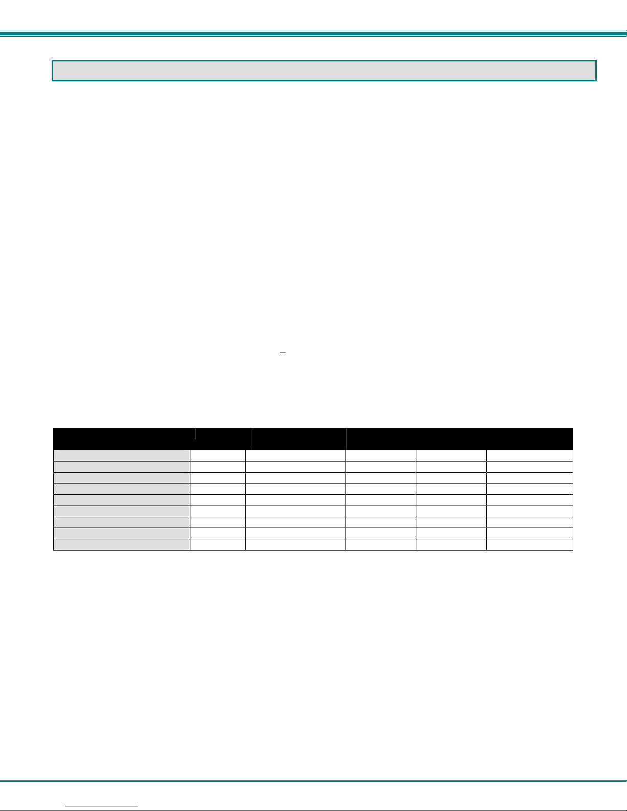
This manual covers each of the XTENDEX Series CAT5-600 Extender models offered. Some features described in this manual
are available in some models and not in others. The chart below shows the features supported in each:
Model Video Keyboard Mouse
ST-C5KVM-600
ST-C5KVMA-600
ST-C5KVMRS-600
ST-C5V-600
ST-C5VA-600
ST-C5VRS-600
ST-C5SV-600
ST-C5SVA-600
ST-C5KVMRS-600-SC5
VGA Yes No No Automatic
VGA Yes Yes No Automatic
VGA Yes No Yes Automatic
VGA No No No Manual
VGA No Yes No Automatic
VGA No No Yes Automatic
S-Video No No No Manual
S-Video No Yes (RCA) No Automatic
VGA Yes No Yes Manual
Support
1Db (models with audio support only)
Audio
Support
RS232
Support
1
Video Quality
Adjustment
NTI EXTENDEX Extenders
MATERIALS
Materials Included with this kit:
9 NTI XTENDEX Local Unit
9 NTI XTENDEX Remote Unit
9 2- 120VAC or 240VAC at 50 or 60Hz-9VDC/1.0A AC Adapters
9 CD with a pdf file of this owner's manual
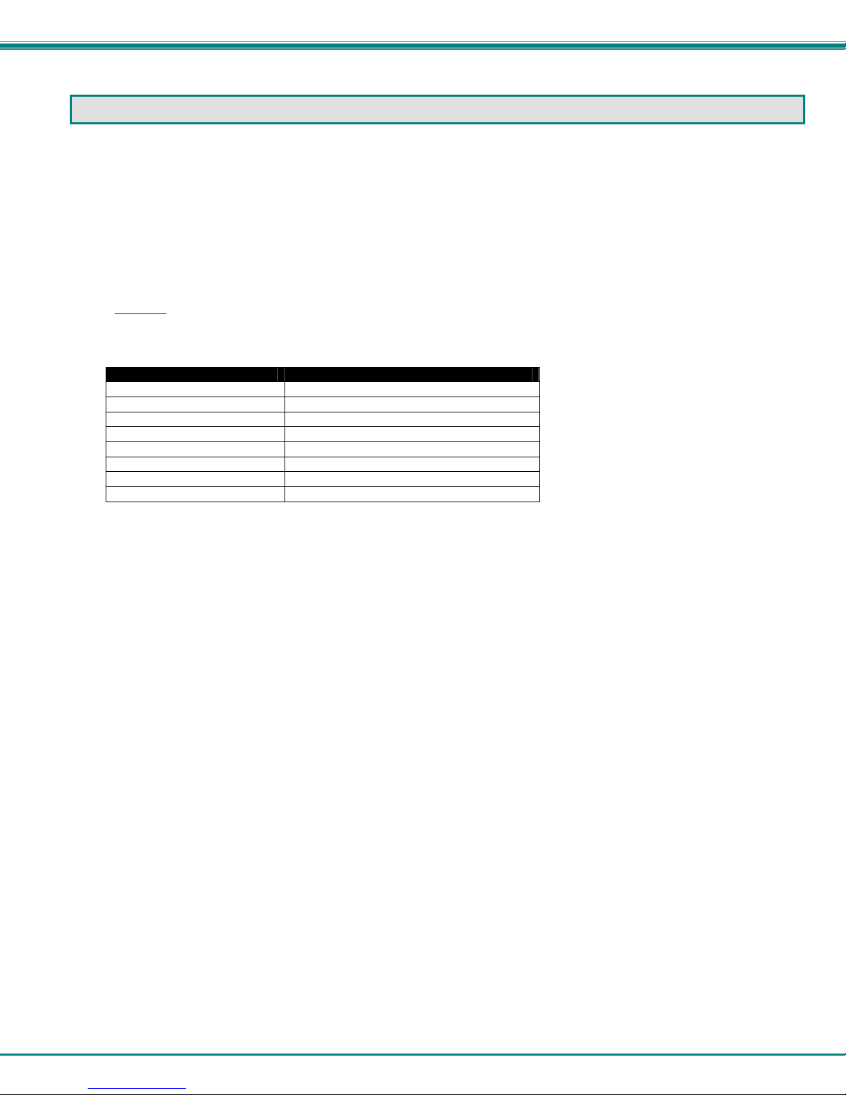
Additional materials may need to be ordered, depending upon the configuration:
¾ CAT5/5e/6 unshielded twisted-pair cable(s) terminated with RJ45 connectors wired straight thru- pin 1 to pin 1, etc. (see pg.
8 for proper EIA/TIA 568 B wiring method)
Note: Shielded
requirements.
¾ Cable(s) needed if Local Unit will be located further than 15" from the CPU
Model Cable(s) needed
ST-C5KVM-600 VKMEXT-xx
ST-C5KVMRS-600 VKMEXT-xx and DINT-xx
ST-C5KVMA-600 VKMEXT-xx and SA-xx-MF
ST-C5V-600 VEXT-xx
ST-C5VRS-600 VEXT-xx and DINT-xx
ST-C5VA-600 VEXT-xx and SA-xx-MF
ST-C5SV-600 SVEXT-xx
ST-C5SVA-600 SVEXT-xx and SA-xx-MF
Contact your nearest NTI distributor or NTI directly for all of your KVM needs at 800-RGB-TECH (800-742-8324) in US & Canada
or 330-562-7070 (Worldwide) or at our website at http://www.networktechinc.com and we will be happ y to be of assistance.
CAT 5,5e, or 6 cable must be used to connect to LOCAL and REMOTE units in order to meet CE emission
2
NTI EXTENDEX Extenders
8a 9 10
8a 9 10
8b 11c
11a
11b
11d
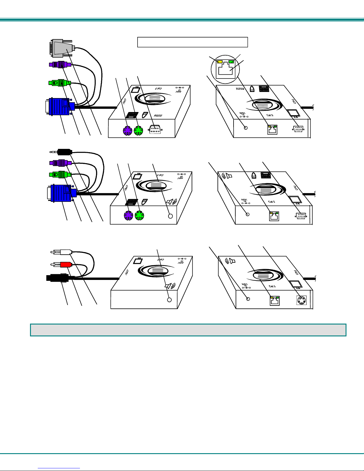
FEATURES AND FUNCTIO NS
2
5a
6
7
+
-
R
NTI
Network T e chnologie s Inc
XTENDEX
15
(Front View) (Rear View)
ST-C5KVMRS-600 Local Unit
6
7
5b
NTI
Network Technologies Inc
XTENDEX
15
+
-
R
(Front View) (Rear View)
ST-C5KVMA-600 Local Unit
15
NTI
Network T e chnologie s Inc
XTENDEX
5b
+
-
R
(Front View) (Rear View)
ST-C5SVA-600 Local Unit
1
3
+
-
3
+
-
3
+
-
R
4a
R
4a
4b
XTENDEX
Network Technologies Inc
NTI
XTENDEX
Network Technologies Inc
NTI
R
XTENDEX
Network T e chnologie s Inc
NTI
FEA TURES AND FUNCTIONS
1. Green LED- traffic indicator- illuminates when there is communication between the local and remote uni ts.
2. Yellow LED- power indicator- illuminates when power has been supplied to the unit
3. Cat 5- RJ45 female- for connecting the CAT 5 cable
4a. Video Connector- 15HD female- for connecting the local user's VGA monitor
4b. S-Video Connector- 4 pin miniDIN female- for connecting the local user's S-video display (S-Video models
5a. RS232 Connector- 9D male- for connecting the local user's touchscreen monitor (models with RS232
support only)
5b. Audio Jack- 3.5mm stereo audio jack- for connecting to local speakers (models with audio support onl y)
6. Mouse Connector- green female 6 miniDIN- for connecting the local user's mouse
7. Keyboard Connector- purple female 6 miniDIN- for connecting the local user's keyboard
only)
3
 Loading...