

NTI XTENDEX, ST-C5KVM-600, ST-C5KVM-600M Installation And Operation Manual
XTENDEX®Series
600 FOOT EXTENDERS
Installation and Operation Manual
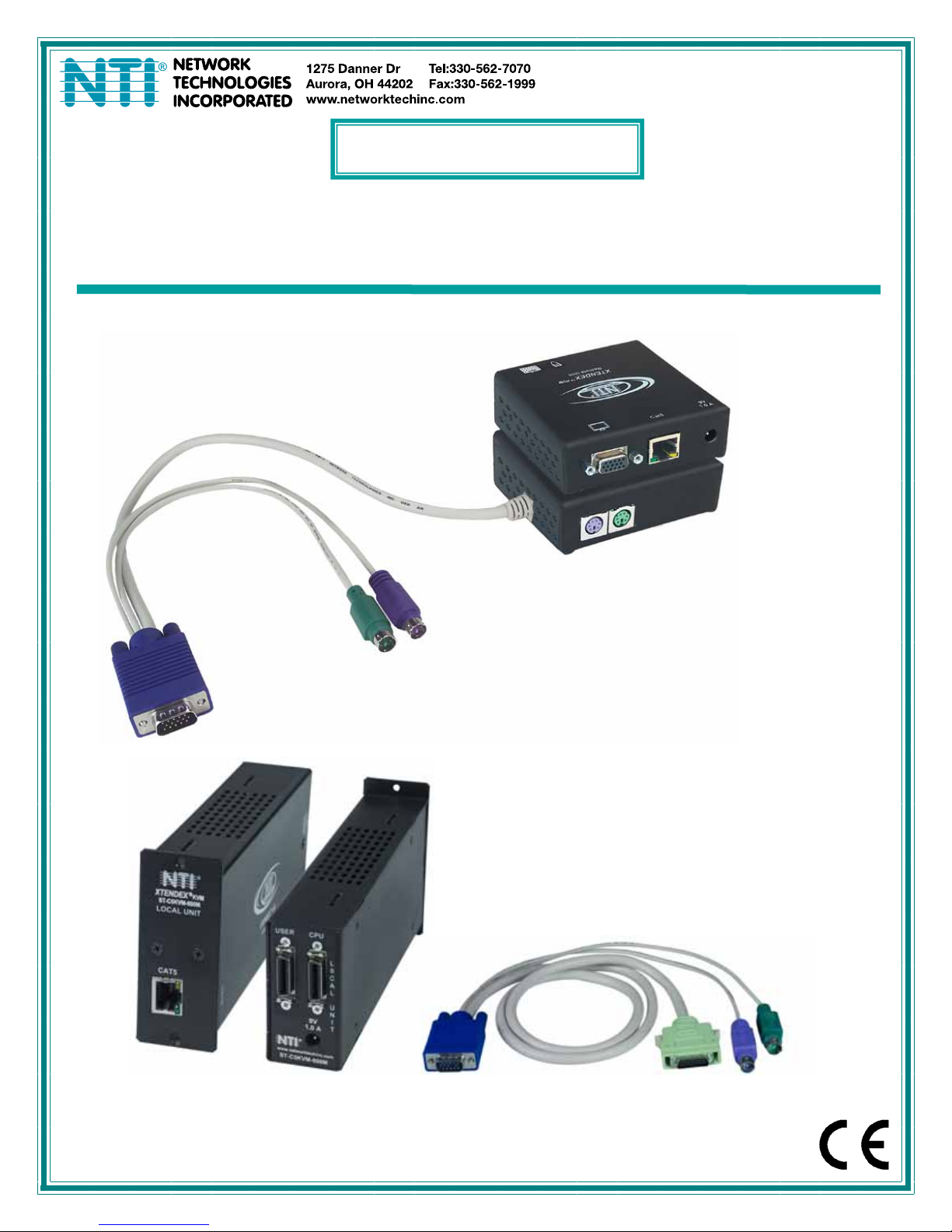
ST-C5KVM-600
PS/2 KVM Extender
ST-C5KVM-600M
PS/2 KVM Extender
VMCTINT-3-MM
(sold separately)
Man014 Rev. 6/26/09

TRADEMARK
XTENDEX is a registered trademark of Network Technologies Inc in the U.S. and other countries.
COPYRIGHT
Copyright © 2003, 2009 by Network Technologies Inc. All rights reserved. No part of this publication may be reproduced, stored
in a retrieval system, or transmitted, in any form or by any means, electronic, mechanical, photocopying, recording, or otherwise,
without the prior written consent of Network Technologies Inc, 1275 Danner Drive, Aurora, Ohio 44202.
CHANGES
The material in this guide is for information only and is subject to change without notice. Network Technologies Inc reserves the
right to make changes in the product design without reservation and without notification to its users.
Note: Shielded
CAT 5,5e, or 6 cable must be used to connect to LOCAL and REMOTE units in order to meet CE emission
and immunity requirements.
Note: CAT5 connection cable used between NTI XTENDEX Series Local and Remote or any XTENDEX Series products
should not be run underground, outdoors or between buildings.
WARNING: Outdoor or underground runs of CAT5 cable could be dangerous and will void the warranty.
CE Statement
We, Network Technologies Inc, declare under our sole responsibility that the ST-C5KVM-600(M), STC5KVMRS-600(M),
STC5VMA-600(M), ST-C5V-600(M), STC5VRS-600(M), ST-C5VA-600(M), ST-C5SV-600, and ST-C5SVA-600 is in conformity
with European Standard EN55022.
Federal Communications Commission Radio Frequency Interference Statement
This device complies with Part 15 of the FCC rules. Operation is subject to the following two conditions:
(1) This device may not cause harmful interference and
(2) this device must accept any interference received, including interference that might cause undesired operation.
This device complies with Part 15 of the FCC rules. This equipment has been tested and found to comply with the limits for a
Class A digital device, pursuant to Part 15 of the FCC rules. These limits are designed to provide reasonable protection against
harmful interference when the equipment is operated in a commercial environment.
Warning: This equipment generates, uses and can radiate radio frequency energy, and, if not installed and used in
accordance with the instruction manual, may cause harmful interference to radio communications.
i

TABLE OF CONTENTS
Introduction...................................................................................................................................................................... 1
Materials .......................................................................................................................................................................... 2
Features and Functions................................................................................................................................................... 4
Limitations ....................................................................................................................................................................... 6
Preparation for Installation ..............................................................................................................................................6
Installation ....................................................................................................................................................................... 7
Installing The Local Unit (models with VGA video connectors).................................................................................. 7
Installing The Local Unit (models with S-Video connectors) ......................................................................................9
Installing the Local Unit (models with only KM connectors) ......................................................................................10
Connect The CAT5 Cable.......................................................................................................................................... 11
Installing The Remote Unit (models with VGA video connectors)............................................................................. 11
Installing The Remote Unit (models with S-Video connectors) ................................................................................. 13
Installing The Remote Unit (models with only KM connectors) .................................................................................14
Connect the CAT5 cable............................................................................................................................................ 14
Plug-in and Boot Up................................................................................................................................................... 15
Rackmount Modules (optional)................................................................................................................................. 16
Mount the ST-C5RCK-12 Rackmount Extender Module Tray................................................................................ 16
Connect the CPU .................................................................................................................................................... 18
Connect the Devices............................................................................................................................................... 19
Connect the CAT5 cable......................................................................................................................................... 20
Plug-in and Boot Up................................................................................................................................................... 21
Video Quality .................................................................................................................................................................22
Technical Specifications................................................................................................................................................ 23
Interconnection Cable Wiring Method ........................................................................................................................... 24
Troubleshooting............................................................................................................................................................. 24
Index..............................................................................................................................................................................25
Warranty Information..................................................................................................................................................... 25
TABLE OF FIGURES
Figure 1- Connect the Local Unit with VGA video and RS232 support to the CPU............................................................................ 7
Figure 2- Connect the Local Unit with Audio support to the CPU ......................................................................................................8
Figure 3- Connect the local user to the XTENDEX Local Unit ...........................................................................................................8
Figure 4- Connect stereo speakers to XTENDEX Local Unit with audio support............................................................................... 9
Figure 5- Connect the S-Video Local Unit to the s-video/audio source.............................................................................................. 9
Figure 6- Connect S-Video display and speakers to Local Unit with s-video support ......................................................................10
Figure 7- Connect Local Unit with only keyboard and mouse support ............................................................................................. 10
Figure 8- Connect CAT5 cable to Local Unit.................................................................................................................................... 11
Figure 9- Connect the Extended Components to the Remote Unit .................................................................................................. 12
Figure 10- Connect speakers to the Remote Unit ............................................................................................................................ 12
Figure 11- Connect components to an S-Video Remote Unit ..........................................................................................................13
Figure 12- Connect keyboard and mouse to Remote Unit ............................................................................................................... 14
Figure 13- Connect the CAT5 cable to the Remote Unit.................................................................................................................. 14
Figure 14- Connect the AC adapter to the Remote Unit ..................................................................................................................15
Figure 15- Mount ST-C5RCK-12 Extender Module Tray in a rack...................................................................................................16
Figure 16- Secure each module to the tray...................................................................................................................................... 16
Figure 17- Secure each power supply to the tray ............................................................................................................................17
Figure 18- Connect cable between CPU and module...................................................................................................................... 18
Figure 19- Connect cable between user and module ......................................................................................................................19
Figure 20- Connect the CAT5 cable between the Local and Remote Units ..................................................................................... 20
Figure 21- Connect AC adapters ..................................................................................................................................................... 21
Figure 22- Buttons for video quality adjustment............................................................................................................................... 22
Figure 23- View looking into RJ45 female........................................................................................................................................ 24
ii
NTI XTENDEX 600 Foot Extenders
INTRODUCTION
The XTENDEX Series CAT5 Extender (XTENDEX) is designed to enable one CPU to be controlled by two users, one local and
one remote. The remote user can be located as much as 600 feet away from a PS/2 CPU via Category 5 unshielded twistedpair cable. The local user will be located near the CPU.
Option:
Rackmount Modules- The XTENDEX Series CAT5 Extenders can be ordered as rackmount modules (Remote and/or Local
Units)- add “M” to the model number (i.e. ST-C5KVM-600M). When ordering rackmount modules, also order the ST-C5RCK-12
Rackmount Extender Module Tray (see page 16).
The XTENDEX Series Extender is extremely simple to install and has been thoroughly tested to insure reliable performance.
Through the use of Category 5 cable it is possible to economically increase the flexibility of a computer system. Here are some of
the features and ways this can benefit any workplace:
• Allows the placement of computer peripherals (monitor, keyboard, and mouse) in a location where
only these parts are needed without having the CPU there too, taking up valuable space
• Allows a PS/2 CPU to be accessed by both a local and remote user (up to 600 feet away)
• Compatible with XGA, VGA, and SVGA systems
• Provides crisp and clear resolution up to 1024 x 768 @ 600 feet (see page 21 for more details)
• Compatible with all NTI switches and splitters, enabling the joining of products to create a system that
satisfies all networking needs
• Video quality adjustment, for varying lengths of cable, is automatic (most models, see below and
page 20) providing optimum image quality
• Audio frequency response is 20Hz to 20Khz, +
• Digital transmission of audio signals reduces any loss in quality (models with audio support only)
This manual covers each of the XTENDEX Series CAT5-600 Extender models offered. Some features described in this manual
are available in some models and not in others. The chart below shows the features supported in each:
Model Video Keyboard Mouse
ST-C5KVM-600
ST-C5KVMA-600
ST-C5KVMRS-600
ST-C5V-600
ST-C5VA-600
ST-C5VRS-600
ST-C5SV-600
ST-C5SVA-600
ST-C5KVMRS-600-SCI
ST-C5KM-600
Note: Rackmount modules are not available with S-Video support
VGA Yes No No Automatic
VGA Yes Yes No Automatic
VGA Yes No Yes Automatic
VGA No No No Manual
VGA No Yes No Automatic
VGA No No Yes Automatic
S-Video No No No Manual
S-Video No Yes (RCA) No Automatic
VGA Yes No Yes Manual
NO Remote only No No Not Applicable
Support
1Db (models with audio support only)
Audio
Support
RS232
Support
1
Video Quality
Adjustment
NTI XTENDEX 600 Foot Extenders
MATERIALS
Materials Included with this kit:
9 NTI XTENDEX Local Unit
9 NTI XTENDEX Remote Unit
9 2- 120VAC or 240VAC at 50 or 60Hz-9VDC/1.0A AC Adapters (only 1 ST-C5KM-600)
9 CD with a pdf file of this owner's manual
Additional materials may need to be ordered, depending upon the configuration:
¾ CAT5/5e/6 unshielded twisted-pair cable(s) terminated with RJ45 connectors wired straight thru- pin 1 to pin 1, etc. (see pg.
8 for proper EIA/TIA 568 B wiring method)
Note: Shielded
requirements.
¾ Cable(s) needed if Local Unit will be located further than 15" from the CPU
Model Cable(s) needed
ST-C5KVM-600 VKMEXT-xx (xx= 3/6/10/15/25/35/50/75/100 feet)
ST-C5KVMRS-600 VKMEXT-xx and DINT-xx
ST-C5KVMA-600 VKMEXT-xx and SA-xx-MF
ST-C5V-600 VEXT-xx
ST-C5VRS-600 VEXT-xx and DINT-xx
ST-C5VA-600 VEXT-xx and SA-xx-MF
ST-C5SV-600 SVEXT-xx
ST-C5SVA-600 SVEXT-xx and SA-xx-MF
ST-C5KM-600 VVKINT-xx or VVKEXT-xx
Cables Lengths Available
Cable xx= Length in feet
VKMEXT-xx 3/6/10/15/25/35/50/75/100
VEXT-xx 3/6/10/15/25/35/50/75/100
DINT-xx 6/10/15
SA-xx-MF 6/12/25/50
SVEXT-xx 1/3/6/10/15/25/35/50/75/100
VVKINT-xx 3/6/10/15/25
VVKEXT-xx 35/50/75/100
For Rackmount Modules the following materials are required- not supplied
Model
ST-C5KVM-600M VMCTINT-xx-MM and VMCTINT-xx
ST-C5KVMRS-600M VMRSTINT-xx-MM and VMRSTINT-xx
ST-C5KVMA-600M VMATINT-xx-MM and VMATINT-xx
ST-C5V-600M VTINT-xx-MM and VTINT-xx
ST-C5VRS-600M VRSTINT-xx-MM and VRSTINT-xx
ST-C5VA-600M VATINT-xx-MM and VATINT-xx
Legend:
xx= 3, 6, 10, 15 or 25 foot length
MM= cables have male connectors on both ends (except for the DB9) and are only used with Local Units
Note: If two users will be connected (one local and one remote), two of the cables without the “MM”
(i.e. VMCTINT-xx) will be needed.
Contact your nearest NTI distributor or NTI directly for all of your KVM needs at 800-RGB-TECH (800-742-8324) in US & Canada
or 330-562-7070 (Worldwide) or at our website at http://www.networktechinc.com and we will be happy to be of assistance.
CAT 5,5e, or 6 cable must be used to connect to LOCAL and REMOTE units in order to meet CE emission
:
Cables needed
2
NTI XTENDEX 600 Foot Extenders
8a 9 10
11a
8a 9 10
11b
8b 11c
11d
6
7
(Front View) (Rear View)
6
7
6
7
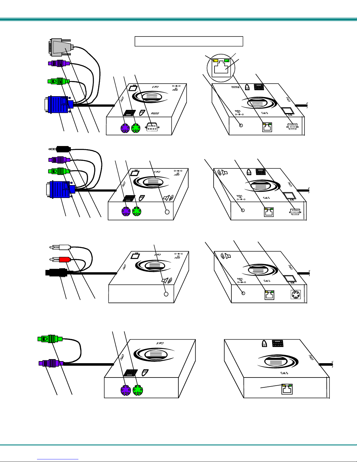
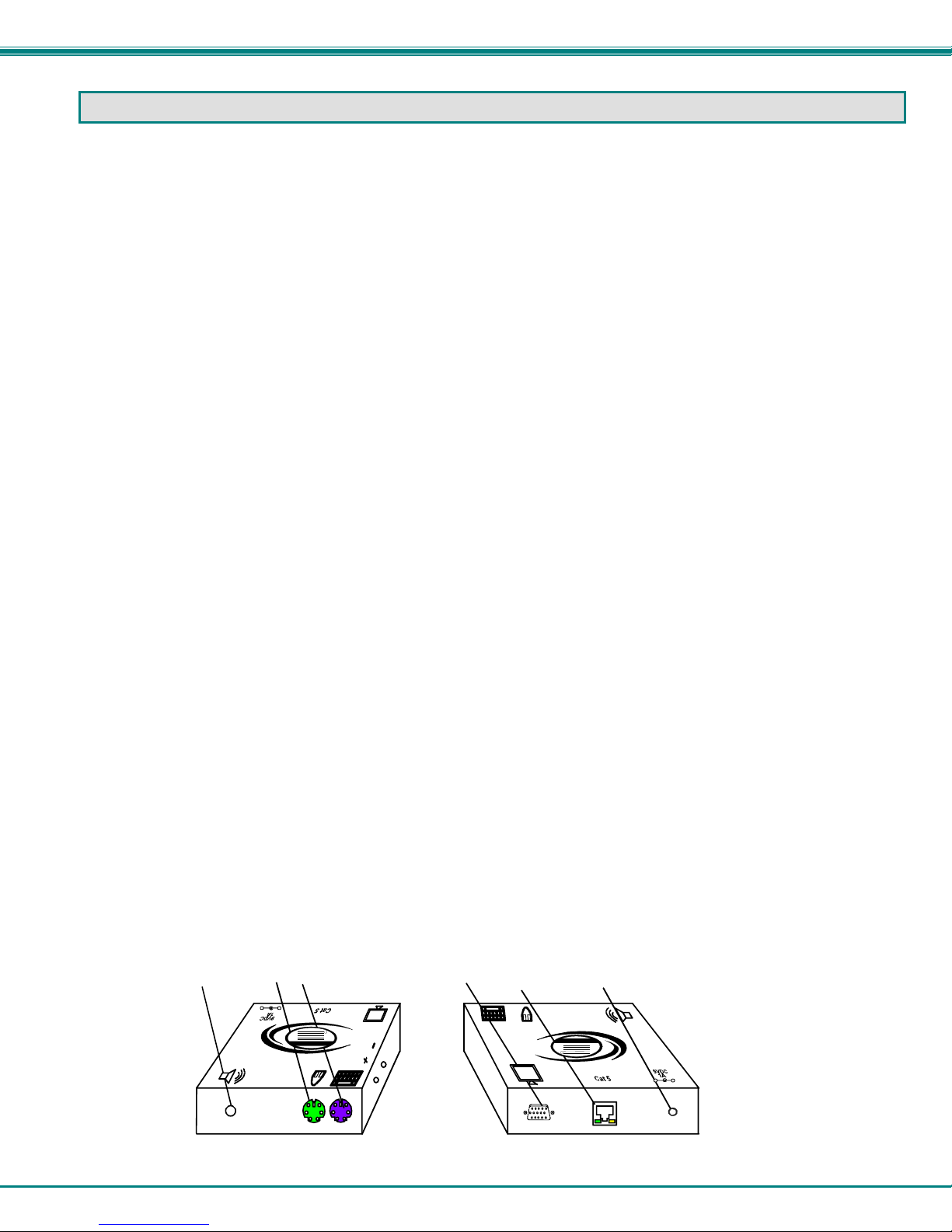
FEATURES AND FUNCTIONS
2
5a
NTI
Network T echnolo gies Inc
XTENDEX
+
-
R
15
ST-C5KVMRS-600 Local Unit
5b
NTI
Network Technologies Inc
XTENDEX
+
-
R
15
(Front View) (Rear View)
ST-C5KVMA-600 Local Unit
15
NTI
Network T echnolo gies Inc
XTENDEX
5b
+
-
R
(Front View) (Rear View)
ST-C5SVA-600 Local Unit
R
NTI
Network Tech nologies Inc
XTENDEX
1
3
4a
XTENDEX
Network Technologies Inc
NTI
R
+
-
3
3
4a
XTENDEX
Network Technologies Inc
NTI
R
+
-
4b
XTENDEX
Network T echnolo gies Inc
NTI
R
+
-
R
XTENDEX
Network Tech nologies Inc
NTI
910
3
(Front View) (Rear View)
ST-C5KM-600 Local Unit
3
NTI XTENDEX 600 Foot Extenders
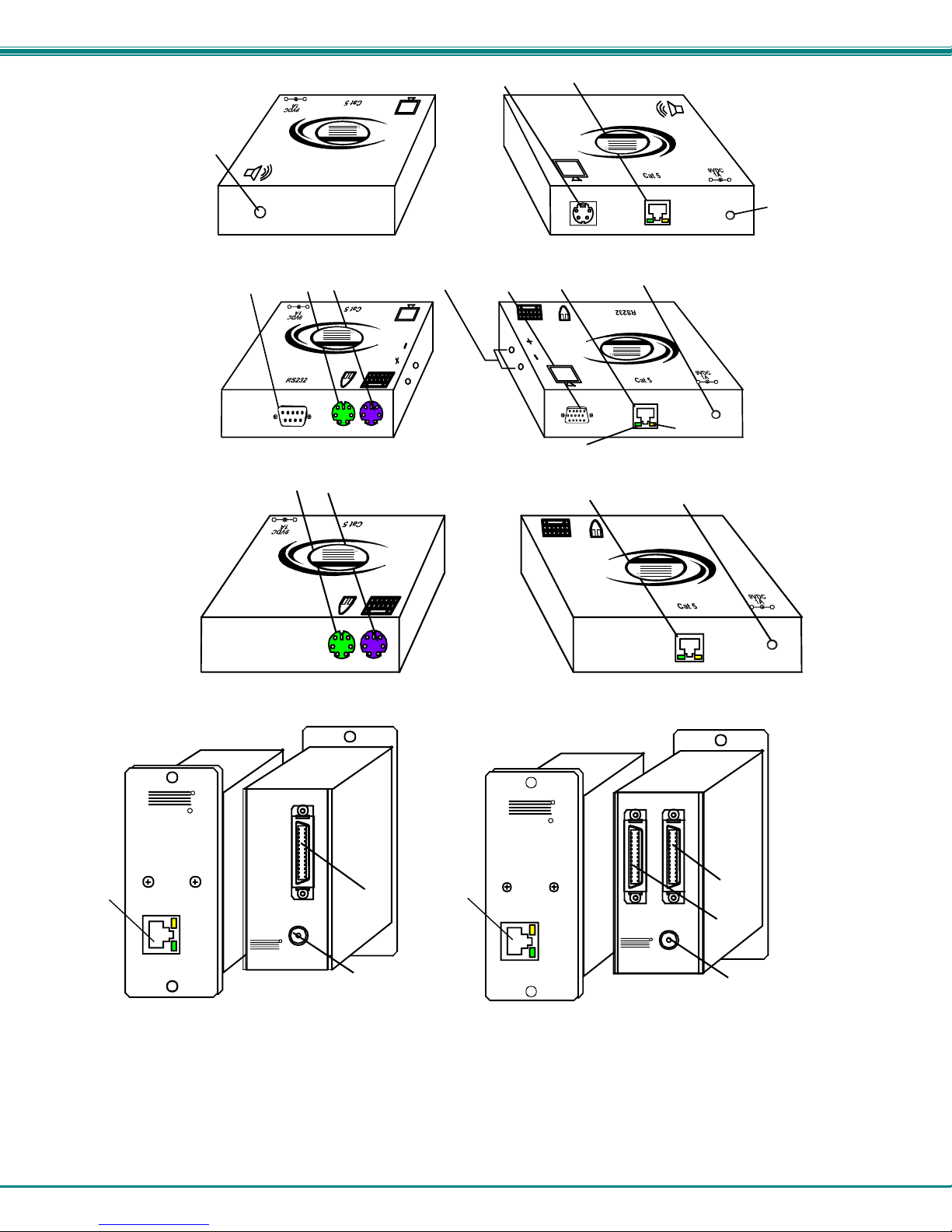
FEATURES AND FUNCTIONS
1. Green LED- traffic indicator- illuminates when there is communication between the local and remote units.
2. Yellow LED- power indicator- illuminates when power has been supplied to the unit
3. Cat 5- RJ45 female- for connecting the CAT 5 cable
4a. Video Connector- 15HD female- for connecting the local user's VGA monitor
4b. S-Video Connector- 4 pin miniDIN female- for connecting the local user's S-video display (S-Video models
5a. RS232 Connector- 9D male- for connecting the local user's touchscreen monitor (models with RS232
support only)
5b. Audio Jack- 3.5mm stereo audio jack- for connecting to local speakers (models with audio support only)
6. Mouse Connector- green female 6 miniDIN- for connecting the local user's mouse
7. Keyboard Connector- purple female 6 miniDIN- for connecting the local user's keyboard
8a. Video Connector- blue 15HD male- for connecting to the video port on the CPU or KVM switch
8b. S-Video Connector- black 4 pin miniDIN male- for connecting to the s-video port on the video source
(S-Video models only)
9. Mouse Connector- green male 6 miniDIN- for connecting to the mouse port on the CPU or KVM switch
10. Keyboard Connector- purple male 6 miniDIN- for connecting to the keyboard port on the CPU or KVM switch
11a. RS232 Connector- light gray 9D female- for connecting to the RS232 port on the CPU or KVM switch
(models with RS232 support only)
11b. Audio Plug- 3.5mm stereo audio plug- for connecting to CPU audio line out (models with audio support
only)
11c. Audio Plug- red RCA plug- for connecting to the right channel audio (model ST-C5SVA-600 only)
11d. Audio Plug- white RCA plug- for connecting to the left channel audio (model ST-C5SVA-600 only)
12. Keyboard Connector- purple female 6 miniDIN- for connecting the remote user's keyboard
13. Mouse Connector- green female 6 miniDIN- for connecting the remote user's mouse
14a. RS232 Connector- 9D male- for connecting the remote user's touchscreen monitor (models with RS232
support only)
14b. Audio Jack- 3.5mm stereo audio jack- for connecting to remote speakers (models with audio support only)
15. 9VDC- 1.0A- connection jack for the AC adapter
16a. Video Connector- 15HD female- for connecting the remote user's monitor
16b. S-Video Connector- 4 pin miniDIN female- for connecting the remote user's S-video display (S-Video
models only)
17. Buttons- for manually adjusting video quality (models ST-C5V-600, ST-C5SV-600, and ST-C5KVMRS-600-SCI only)
14b
only)
1213
+
-
NTI
Network Technologies Inc
XTENDEX
(Front View) (Rear View)
16a
R
ST-C5KVMA-600 Remote Unit
3
15
XTENDEX
Network Tec hnologies Inc
NTI
R
+
-
4
NTI XTENDEX 600 Foot Extenders
+
14b
-
R
NTI
Network Technolo gies Inc
XTENDEX
16b
3
Network Technolo gies Inc
NTI
R
(Front View) (Rear View)
12
-
13
+
XTENDEX
NTI
Network Tec hnologies Inc
14a
ST-C5SVA-600 Remote Unit
17
R
16a
3
R
15
Network Tec hnologies Inc
NTI
(Front View) (Rear View)
ST-C5KVMRS-600-SCI Remote Unit
1213
+
-
1
3
R
NTI
Network Tech nologies Inc
XTENDEX
R
(Front View) (Rear View)
ST-C5KM-600 Remote Unit
3
XTENDEX
ST-C5KVM-600M
REMOTE UNIT
NTI
CAT5
R
R
KVM
USER
9V
1.0 A
R
NTI
www.netw orktechin c.com
ST-C5KVM- 600M
R
NTI
LOCAL UNIT
CAT5
R
KVM
XTENDEX
R
E
M
O
T
E
U
N
T
18
I
ST-C5KVM-600M
3
USER
NTI
www.netw orktechin c.com
ST-C5KVM-600M
15
ST-C5KVM-600M
Remote Module
Front and Rear Views
ST-C5KVM-600M
Local Module
Front and Rear Views
(All XTENDEX 600 foot extender modules have the same connections)
18. USER- .05 SCSI II Female- for connecting cable between module and the user devices
19. CPU- .05 SCSI II Female- for connecting cable between the module and the CPU
R
XTENDEX
XTENDEX
1.0 A
CPU
9V
2
15
Network Tech nologies Inc
NTI
+
-
15
+
-
XTENDEX
+
-
L
0
C
A
L
U
19
N
I
T
18
15
5
NTI XTENDEX 600 Foot Extenders
LIMITATIONS
• Hot-plugging of devices is supported provided devices were originally connected at power-up.
• In order for two users to share a PS/2 CPU, the user in control must pause for at least 3 seconds before another user can
take control. After the 3 second pause, either user can take control of the CPU.
For models with RS232 support:
• The RS232 ports on the Local and Remote Units will support serial devices other than touchscreen monitors as follows:
• 2 simple devices (i.e. mice) connected to each
• 1 complex device (i.e. serial modem, RS232 command port on an NTI switch) connected to
either
• In order for two users to share a PS/2 CPU, the user in control must pause for at least 3 seconds before another user can
take control. After the 3 second pause, either user can take control of the CPU.
• The RS232 port supports all baud rates up to 56K bits per second and the attached CPU must be configured accordingly.
For models with audio support:
• The audio input of the XTENDEX with audio support is compatible with the following standard CPU audio outputs:
• To connect the ST-C5SVA-600 to a CPU, it may be necessary to use an RCA phono-to-3.5mm stereo jack adapter
• The audio output of the XTENDEX with audio support is compatible with self-powered stereo speakers.
the Remote or Local Unit.
• Line out - typically lime green in color
• Speaker out- typically orange in color
• Headphone out- typically located on the CD-ROM
unit, or
PREPARATION FOR INSTALLATION
• Locations should be chosen for the monitors, mice, and keyboards that also have space to connect the Remote and Local
Units within the distance provided by the cables. If extension cables are needed, contact NTI for the cables required.
• The CAT5 cables must be run to the locations where the Remote and Local Units will be connected. Be careful to route the
cables away from any sources of magnetic fields or electrical interference that might reduce the quality of the video signal
(i.e. AC motors, welding equipment, etc.).
• All cables should be installed in such a way that they do not cause stress on their connections to the equipment. Extended
lengths of cable hanging from a connection may interfere with the quality of that connection. Secure cables as needed to
minimize this.
• Properly shut down and disconnect the power from the CPU and monitors to be separated. If other equipment is involved
whose connections are being interrupted, be sure to refer to the instruction manuals for that equipment for proper
disconnection and re-connection procedures before proceeding.
Note: CAT5 connection cable used between NTI XTENDEX Series Local and Remote or any XTENDEX Series products
should not be run underground, outdoors or between buildings.
WARNING: Outdoor or underground runs of CAT5 cable could be dangerous and will void the warranty.
6
 Loading...