

NTI ST-2C5VA-L-600, ST-C5V-600, ST-C5VRS-600, ST-2C5V-L-600, ST-C5KVMRS-600-SCI Installation And Operation Manual
...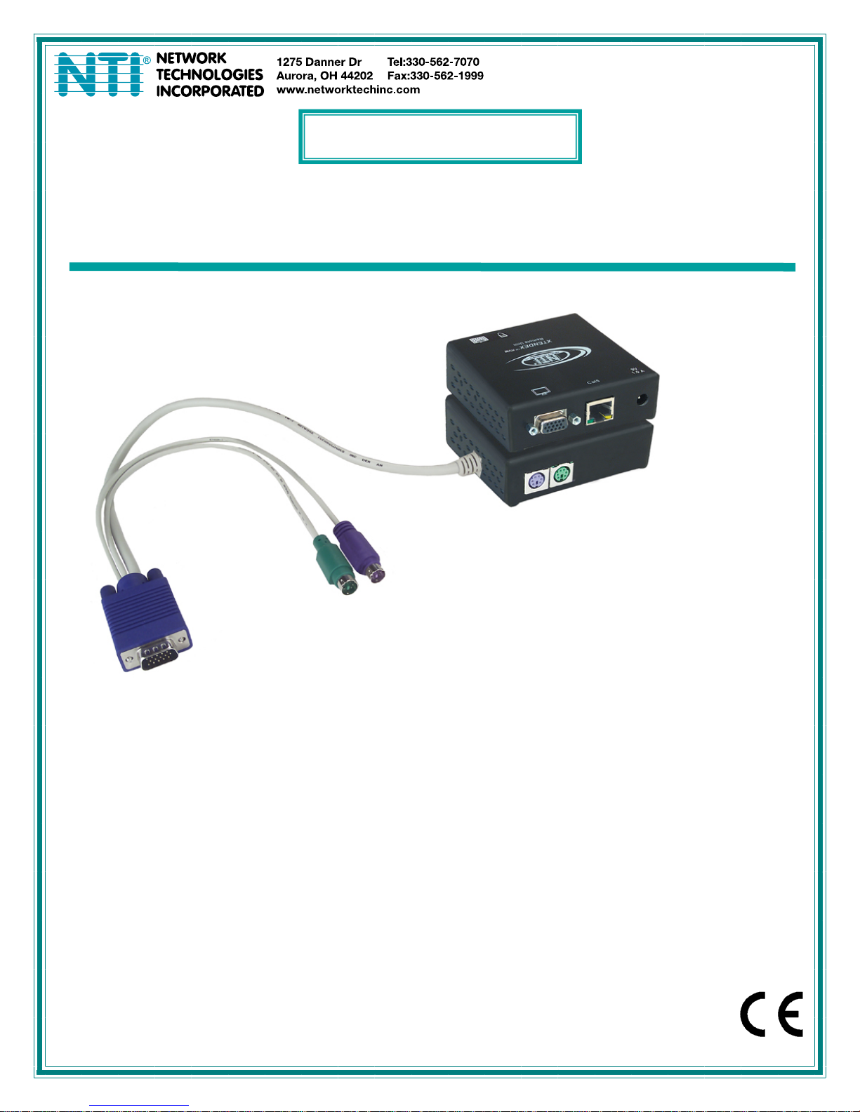
XTENDEX
®
Series
600 FOOT EXTENDERS
Installation and Operation Manual
ST-C5KVM-600
PS/2 KVM Extender
Man014 Rev. 9/11/18
TRADEMARK
XTENDEX is a registered trademark of Network Technologies Inc in the U.S. and other countries.
COPYRIGHT
Copyright © 2003, 2018 by Network Technologies Inc. All rights reserved. No part of this publication may be reproduced, stored
in a retrieval system, or transmitted, in any form or by any means, electronic, mechanical, photocopying, recording, or otherwise,
without the prior written consent of Network Technologies Inc, 1275 Danner Drive, Aurora, Ohio 44202.
CHANGES
The material in this guide is for information only and is subject to change without notice. Network Technologies Inc reserves the
right to make changes in the product design without reservation and without notification to its users.
Note: Shielded
CAT 5,5e, or 6 cable must be used to connect to LOCAL and REMOTE units in order to meet CE emission
and immunity requirements.
Note: CATx connection cable used between NTI XTENDEX Series Local and Remote or any XTENDEX Series products
should not be run underground, outdoors or between buildings.
WARNING: Outdoor or underground runs of CATX cable could be dangerous and will void the warranty.
WARNING: The CATx connection cable used between NTI XTENDEX Series Local and Remote or any XTENDEX Series
products must be wired straight through (pin 1 to pin 1, pin 2 to pin 2, etc.) The use of a CROSSOVER CABLE will
damage the extender and void your warranty.
CE Statement
We, Network Technologies Inc, declare under our sole responsibility that the ST-C5KVM-600, STC5KVMRS-600, STC5KVMA600, ST-C5V-600, STC5VRS-600 and ST-C5VA-600 is in conformity with European Standard EN55022.
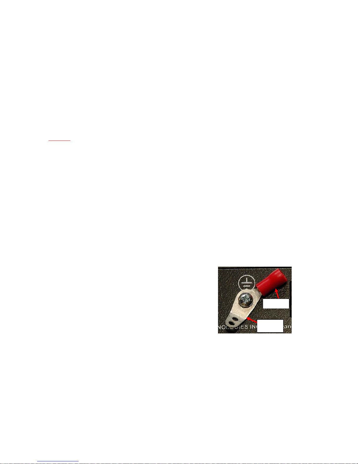
External Ground
This product is equipped with grounding hardware to prevent interference
from sources of electrical noise that could interfere with the normal operation
of the XTENDEX or damage it. Use either the crimp-on lug or solder terminal
to secure a properly grounded wire (connected to earth ground) to the
XTENDEX.
Failure to make this connection may result in poor video quality at the
connected monitor(s).
Crimp-on
Solder
terminal
i

TABLE OF CONTENTS
Introduction....................................................................................................................................................................1
Materials.........................................................................................................................................................................2
Features and Functions................................................................................................................................................4
Limitations .....................................................................................................................................................................6
Preparation for Installation...........................................................................................................................................7
Installation......................................................................................................................................................................8
Installing The Local Unit (models with VGA video connectors)..................................................................................8
Installing the Local Unit (models with only KM connectors)......................................................................................10
Connect The CATx Cable..........................................................................................................................................11
Installing The Remote Unit (models with VGA video connectors).............................................................................11
Installing The Remote Unit (models with only KM connectors).................................................................................13
Connect the CATx cable......................................................................................................... ...................................13
Models With One Remote.......................................................................................................................................13
Models With Two Remotes.....................................................................................................................................14
Plug-in and Boot Up...................................................................................................................................................15
Video Quality ...............................................................................................................................................................16
Command Mode........................................................................................................................................................17
Enter Command Mode............................................................................................................................................17
General Video Quality Adjustment ......................................................................................................................17
Update DDC at Remote.......................................................................................................................................17
Update DDC at Local...........................................................................................................................................17
Mix DDC ..............................................................................................................................................................18
Reset Defaults.....................................................................................................................................................18
Exit Command Mode ..............................................................................................................................................18
Other DDC Support ...................................................................................................................................................18
Automatic EDID Updates........................................................................................................................................18
Manual EDID Capture.............................................................................................................................................19
More About DDC .................................................................................................................................................20
Technical Specifications ............................................................................................................................................21
Interconnection Cable Wiring Method ......................................................................................................................22
Troubleshooting..........................................................................................................................................................23
Index.............................................................................................................................................................................24
Warranty Information..................................................................................................................................................24
TABLE OF FIGURES
Figure 1- Connect the Local Unit with VGA video and RS232 support to the CPU............................................................................8
Figure 2- Connect the Local Unit with Audio support to the CPU ......................................................................................................9
Figure 3- Connect the local user to the XTENDEX Local Unit...........................................................................................................9
Figure 4- Connect stereo speakers to XTENDEX Local Unit with audio support.............................................................................10
Figure 5- Connect Local Unit with only keyboard and mouse support.............................................................................................10
Figure 6- Connect CATx cable to Local Unit....................................................................................................................................11
Figure 7- Connect the Extended Components to the Remote Unit..................................................................................................12
Figure 8- Connect speakers to the Remote Unit..............................................................................................................................12
Figure 9- Connect keyboard and mouse to Remote Unit.................................................................................................................13
Figure 10- Connect the CATx cable to the Remote Unit..................................................................................................................13
Figure 11- Connect CATx cables between Local and Remote Units ...............................................................................................14
Figure 12- Connect the AC adapter to the Remote Unit ..................................................................................................................15
Figure 13- Buttons for video quality adjustment...............................................................................................................................16
Figure 14- DDC Update Button on Local with Dual Remote Support...............................................................................................19
Figure 15- Connect remote monitor for EDID capture .....................................................................................................................19
Figure 16- View looking into RJ45 female........................................................................................................................................22
ii
NTI XTENDEX 600 Foot Extenders
INTRODUCTION
The XTENDEX Series CAT5 Extender (XTENDEX) is designed to enable one CPU to be controll ed by two users, one local and
one remote. The remote user can be located as much as 600 feet away from a PS/2 CPU via Category 5/5e/6 (CATx)
unshielded twisted-pair cable. The local user will be located near the CP U.
Options:
Local Supporting Two Remotes- The XTENDEX series 600 foot PS/2 extender is available supporting two Remote Units from a
single Local Unit if needed. See chart below for available models and features. When ordering the XTENDEX with dual Remote
support, Remote Units are ordered separately.
The XTENDEX Series Extender is extremely simple to install and has been thoroughly tested to insure reliab le p erformance.
Through the use of Category 5\5e\6 cable it is possible to economically increase the flexibility of a computer system. Here are
some of the features and ways this can benefit any workplace:
Allows the placement of computer peripherals (monitor, keyboard, and mouse) in a location wh ere
only these parts are needed without having the CPU there too, taking up valuable space
Allows a PS/2 CPU to be accessed by both a local and remote user (up to 600 feet awa y)(most models-see chart below)
Compatible with XGA and VGA systems
Provides crisp and clear resolution up to 1024 x 768 @ 600 feet (see pa ge 21 for more details)
Compatible with all NTI switches and splitters, enabling the joining of products to create a system that
satisfies all networking needs
Video quality adjustment, for varying lengths of cable, is automatic (most models, see below and
page 20) providing optimum image quality
Audio frequency response is 20Hz to 20Khz, + 1dB (models with audio s upport only)
Digital transmission of audio signals reduces any loss in quality (models with audio support only)
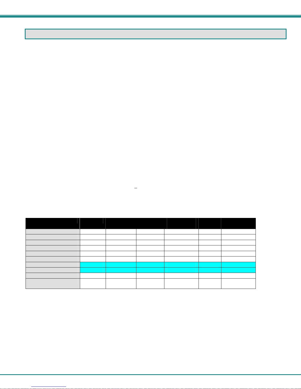
This manual covers each of the XTENDEX Series CAT5-600 Extender models offered. Some features described in this manual
are available in some models and not in others. The chart below shows the features supported in each:
Model Video Kybd/ Mse
ST-C5KVM-600
ST-C5KVMA-600
ST-C5KVMRS-600
ST-C5V-600
ST-C5VA-600
ST-C5VRS-600
ST-2C5V-L-600
ST-2C5VA-L-600
ST-C5KVMRS-600-SCI
ST-C5KM-600
Note: Models shaded in blue (ST-2C5V(A)-L-600) provide Remote Unit-only support for devices, no L ocal Unit support.
VGA Yes No 1 No Automatic
VGA Yes Yes 1 No Automatic
VGA Yes No 1 Yes Automatic
VGA No No 1 No Manual
VGA No Yes 1 No Automatic
VGA No No 1 Yes Automatic
VGA No No 2 No Manual
VGA No Yes 2 No Automatic
VGA Yes No 1 Yes Manual
NO On Remote
Support
only
Audio
Support
# of Remotes
Supported
RS232
Support
Video Quality
Adjustment
No 1 No Not Applicable
1
NTI XTENDEX 600 Foot Extenders
MATERIALS
Materials supplied with ST-C5xxxx-600:
NTI XTENDEX Local Unit
NTI XTENDEX Remote Unit
2- 120VAC or 240VAC at 50 or 60Hz-9VDC/1.0A AC Adapters (only 1 ST-C5KM-600)
Materials supplied with ST-2C5xxxx-L-600:
NTI XTENDEX Local Unit
1- 120VAC or 240VAC at 50 or 60Hz-9VDC/1.0A AC Adapter
Additional materials may need to be ordered, depending upon the configuration:
CAT5/5e/6 unshielded twisted-pair cable(s) terminated with RJ45 connectors wired straight thru- pin 1 to pin 1, etc. (see pg.
8 for proper EIA/TIA 568 B wiring method)
Note: Shielded CAT5, 5e, or 6 cable must be used to connect to LOCAL and REMOTE units in order to meet CE emission
requirements.
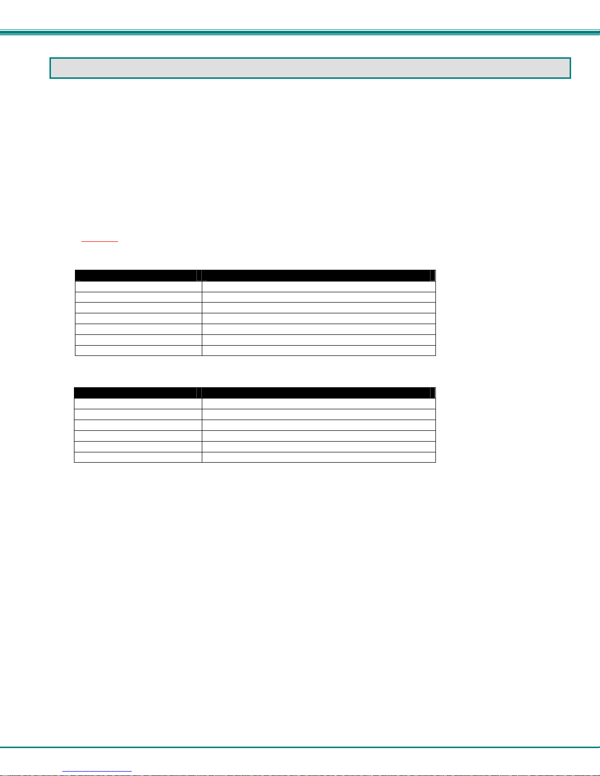
Cable(s) needed if Local Unit will be located further than 15" from the CPU
Model Cable(s) needed
ST-C5KVM-600 VKMEXT-xx (xx= 3/6/10/15/25/35/50/75/100 feet)
ST-C5KVMRS-600 VKMEXT-xx and DINT-xx
ST-C5KVMA-600 VKMEXT-xx and SA-xx-MF
ST-C5V-600 VEXT-xx
ST-C5VRS-600 VEXT-xx and DINT-xx
ST-C5VA-600 VEXT-xx and SA-xx-MF
ST-C5KM-600 VVKINT-xx or VVKEXT-xx
The chart above also applies to Local Unit models with support for two remotes.
Cables Lengths Available
Cable xx= Length in feet
VKMEXT-xx 3/6/10/15/25/35/50/75/100
VEXT-xx 3/6/10/15/25/35/50/75/100
DINT-xx 6/10/15
SA-xx-MF 6/12/25/50
VVKINT-xx 3/6/10/15/25
VVKEXT-xx 35/50/75/100
Legend:
xx= 3, 6, 10, 15 or 25 foot length
MM= cables have male connectors on both ends (except for the DB9) and are only used with Local Units
Note: If two users will be connected (one local and one remote), two of the cables without the “MM”
(i.e. VMCTINT-xx) will be needed.
Contact your nearest NTI distributor or NTI directly for all of your KVM needs at 800-RGB-TECH (800-742-8324) in US & Canada
or 330-562-7070 (Worldwide) or at our website at http://www.networktechinc.com and we will be happy to be of assistance.
2
NTI XTENDEX 600 Foot Extenders
3

NTI XTENDEX 600 Foot Extenders
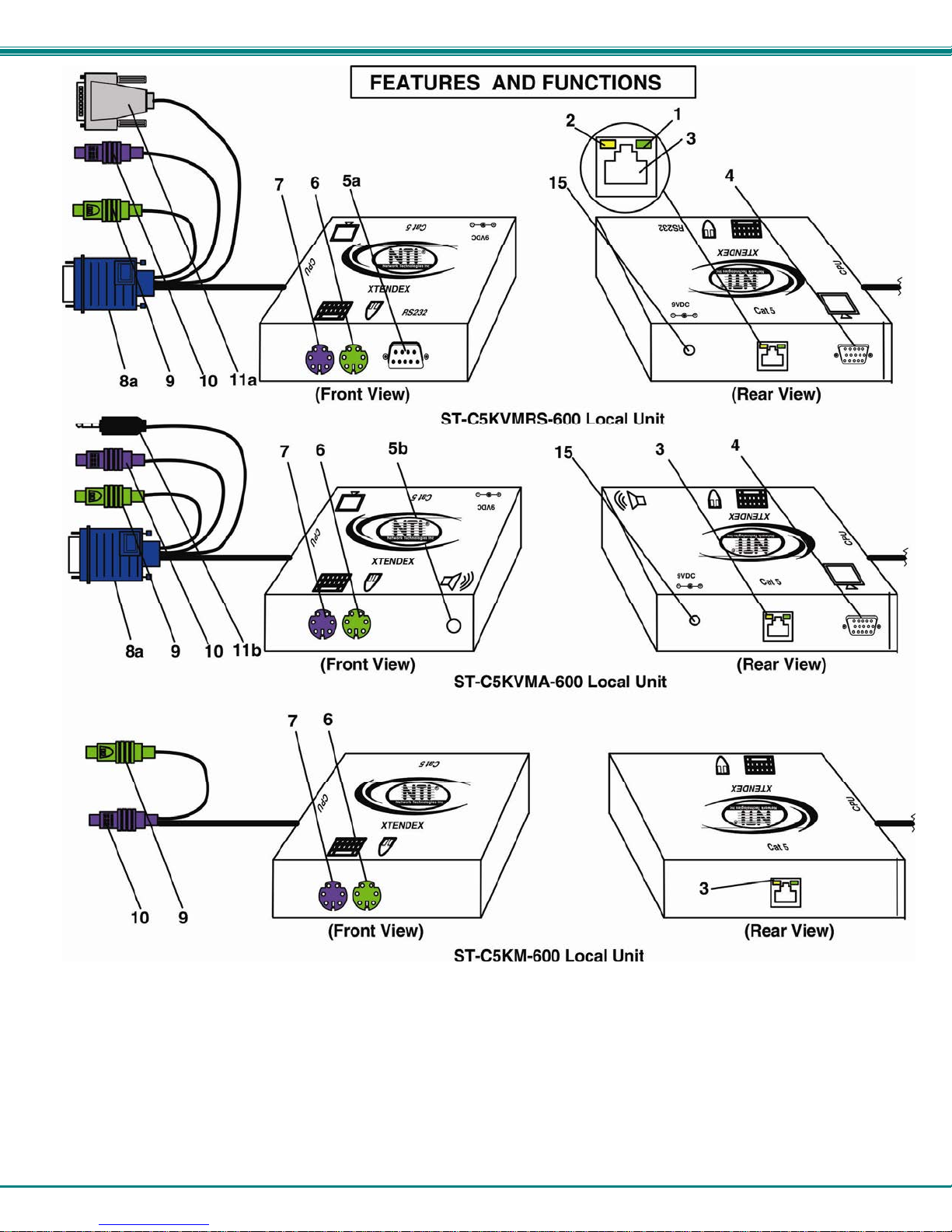
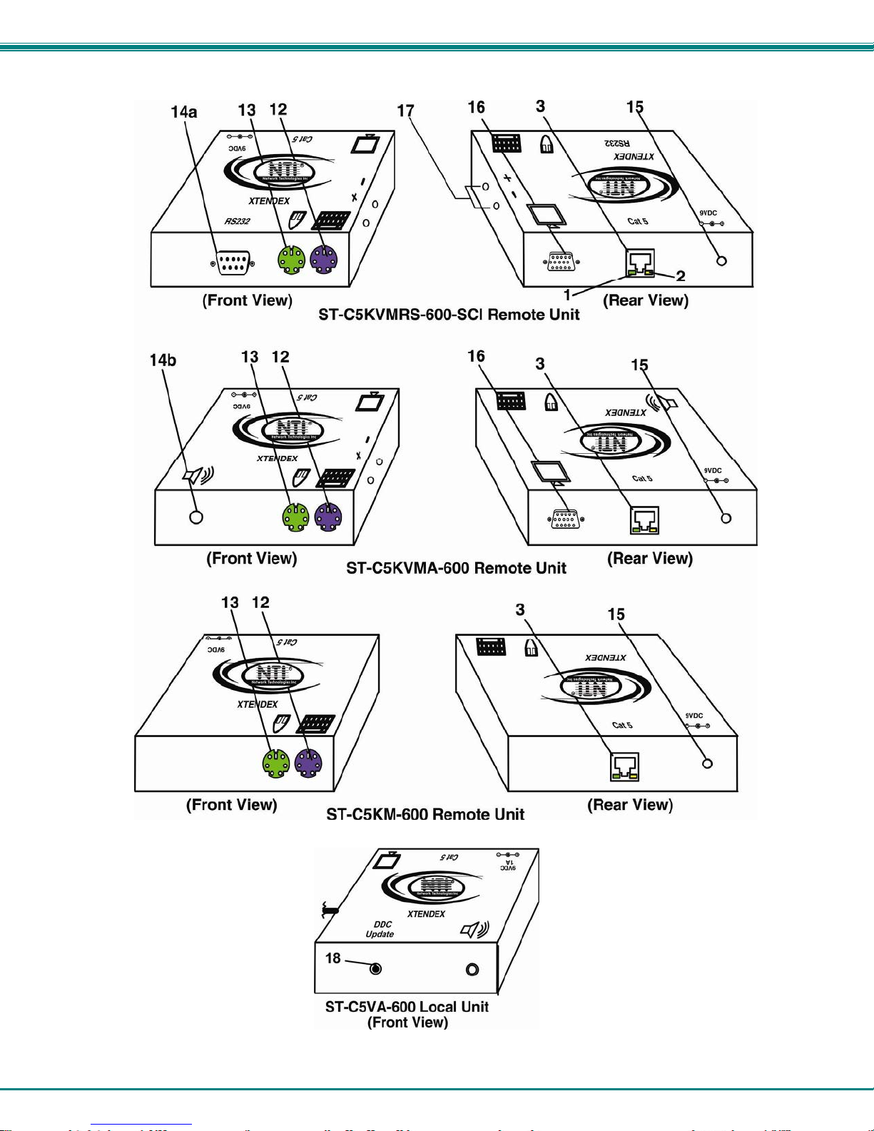
FEATURES AND FUNCTIONS
1. Green LED- power indicator- illuminates when power has been supplied to the unit
2. Yellow LED- traffic indicator- illuminates when there is communication between the local and remote units.
3. Cat 5- RJ45 female- for connecting the CAT 5 cable
4. Video Connector- 15HD female- for connecting the local user's VGA monitor
5a. RS232 Connector- 9D male- for connecting the local user's touchscreen monitor (models with RS232
support only)
5b. Audio Jack- 3.5mm stereo audio jack- for connecting to local speakers (models with audio support only)
6. Mouse Connector- green female 6 miniDIN- for connecting the local user's mouse
7. Keyboard Connector- purple female 6 miniDIN- for connecting the local user's keyboard
8. Video Connector- blue 15HD male- for connecting to the video port on the CPU or KVM switch
9. Mouse Connector- green male 6 miniDIN- for connecting to the mouse port on the CPU or KVM switch
10. Keyboard Connector- purple male 6 miniDIN- for connecting to the keyboard port on the CPU or KVM switch
11a. RS232 Connector- light gray 9D female- for connecting to the RS232 port on the CPU or KVM switch
(models with RS232 support only)
11b. Audio Plug- 3.5mm stereo audio plug- for connecting to CPU audio line out (models with audio support
only)
12. Keyboard Connector- purple female 6 miniDIN- for connecting the remote user's keyboard
13. Mouse Connector- green female 6 miniDIN- for connecting the remote user's mouse
14a. RS232 Connector- 9D male- for connecting the remote user's touchscreen monitor (models with RS232
support only)
14b. Audio Jack- 3.5mm stereo audio jack- for connecting to remote speakers (models with audio support only)
15. 9VDC- 1.0A- connection jack for the AC adapter
16. Video Connector- 15HD female- for connecting the remote user's monitor
17. Buttons- for manually adjusting video quality (models ST-C5V-600 and ST-C5KVMRS-600-SCI only)
18. DDC Update- Button used to send updated EDID to the graphics card in the CPU (supported models only)
Note: The 15HD female port on the ST-2C5V(A)-L-600 is used for EDID capture only (see page 18).
4
NTI XTENDEX 600 Foot Extenders
5

NTI XTENDEX 600 Foot Extenders
LIMITATIONS
Hot-plugging of devices is supported provided devices were originally conn ected at power-up.
In order for two users to share a PS/2 CPU, the user in control must pause for at least 3 seconds before another user can
take control. After the 3 second pause, either user can take control of the CPU.
For models with RS232 support:
The RS232 ports on the Local and Remote Units will support serial devices other than touchscreen monitors as follows:
2 simple devices (i.e. mice) connected to each
1 complex device (i.e. serial modem, RS232 command port on an NTI switch) connected to
either
In order for two users to share a PS/2 CPU, the user in control must pause for at least 3 seconds before another user can
take control. After the 3 second pause, either user can take control of the CPU.
The RS232 port supports all baud rates up to 56K bits per second and the attached CPU must be configured accordingly.
For models with audio support:
The audio input of the XTENDEX with audio support is compatible with the following standard CPU aud io outputs:
The audio output of the XTENDEX with audio support is compatible with self-powered stereo speakers.
the Remote or Local Unit.
Line out - typically lime green in color
Speaker out- typically orange in color
Headphone out- typically located on the CD-ROM
unit, or
6
 Loading...