

NTI ST-8U-R, ST-8U-RO, ST-4U-RO, ST-4U-R Installation And User Manual
NTINTI
NETWORK
TECHNOLOGIES
INCORPORATED
1275 Danner Dr
Aurora, OH 44202
Tel:330-562-7070
Fax:330-562-1999
ST-xU (Universal KVM Switch)
INSTALLATION / USER GUIDE
MAN064 Rev Date 11/23/2001
VGA
Multi-Scan
Monitor
Macintosh
SUN WORKSTATION
PS/2
PS/2
PC, SUN, or MAC Keyboard / Mouse
ST-8U
NETWORK
TECHNOLOGIES
NTI
INCORPORATED
2 3 4 5 6 7 8
1
SCAN
OFF
ON
MODE
BROAD
CAST
1 2 3 4 5 6 7 8
COM
MAND
REMOTE REMOTE
OUT IN
PS/2
Macintosh
SUN WORKSTATION
PS/2

TABLE OF CONTENTS
INTRODUCTION ..................................................................................................................................................................................................1
MATERIALS ...........................................................................................................................................................................................................2
Materials Supplied with this kit:...................................................................................................................................................................2
Materials Not Supplied, but REQUIRED:.................................................................................................................................................2
INSTALLATION .....................................................................................................................................................................................................3
1. LIMITATIONS ...........................................................................................................................................................................................7
2. CASCADED INSTALLATION.................................................................................................................................................................8
3. CONFIGURATION OF DIP-SWITCHES 1-6:....................................................................................................................................9
USING THE NTI UNIVERSAL KVM SWITCH ............................................................................................................................................9
FRONT PANEL CONTROL ..........................................................................................................................................................................9
MODES OF OPERATION ...........................................................................................................................................................................10
1. BASIC COMMAND MODE....................................................................................................................................................................10
2. SCAN MODE.............................................................................................................................................................................................11
3. BROADCAST MODE ..............................................................................................................................................................................11
4. NORMAL MODE.......................................................................................................................................................................................11
OPTIONAL OSD SECURITY ADMINISTRATION ..................................................................................................................................11
USING THE SECURITY FEATURE ........................................................................................................................................................12
USER LOGIN MODE ....................................................................................................................................................................................12
ADMINISTRATION MODE..........................................................................................................................................................................13
USER NAME LIST.........................................................................................................................................................................................13
SYSTEM ACCESS LIST..............................................................................................................................................................................13
OPTIONAL OSD CONTROL..........................................................................................................................................................................14
OSD COMMAND MODE .............................................................................................................................................................................14
SCAN MODE ...................................................................................................................................................................................................15
BROADCAST MODE....................................................................................................................................................................................15
NORMAL MODE.............................................................................................................................................................................................15
EDIT MODE......................................................................................................................................................................................................16
SEARCH MODE.............................................................................................................................................................................................16
MAINTENANCE MODE ...............................................................................................................................................................................17
HELP MODE....................................................................................................................................................................................................18
Other Control Options.......................................................................................................................................................................................18
Keyboard Mapping .............................................................................................................................................................................................18
KEYBOARD-TO-COMPUTER TRANSLATION .......................................................................................................................................19
Mouse Click Equivalents..............................................................................................................................................................................19
HOW TO DISABLE OPERATING MODES ...............................................................................................................................................19
CONFIGURING THE JUMPER BLOCK.................................................................................................................................................23
TECHNICAL SPECIFICATIONS ...................................................................................................................................................................23
TROUBLESHOOTING ......................................................................................................................................................................................24
WARRANTY INFORMATION.........................................................................................................................................................................24
COPYRIGHT ....................................................................................................................................................................................................24
CHANGES ........................................................................................................................................................................................................24

1
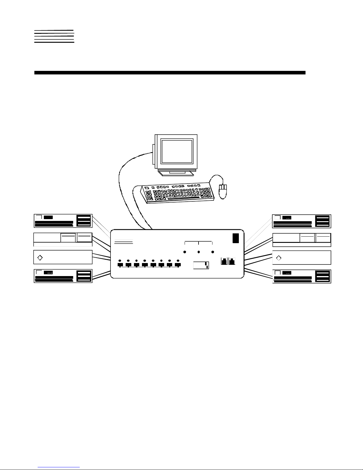
INTRODUCTION
The NTI UNIVERSAL KVM Switch connects the user’s keyboard, monitor, and mouse directly to any legacy PC, MAC, or SUN
workstation connected to the switch (up to 32 computers as a single switch or 152 computers when switches are cascaded).
These computers can be file servers, network managers, etc. Through the connection made by the Universal KVM switch, the
user is able to control any one workstation connected to the system. The microprocessor driven circuitry in the NTI Switch allows
all computers to boot simultaneously without keyboard error.
NOTE: A VGA multi-scan monitor must be used with this product unless you have purchased an ST-xU-13W3 which will
also work with a multi-scan PC compatible SUN monitor.
Available Options:
• Switch models are available in 60 or 50 Hz, and 110 or 220V.
• Built-in 13W3 monitor port for SUN multi-scan PC compatible monitors. (Model ST-xU-13W3)
• LCD display (Allows selection and control of computers by name through a display on the front panel of the switch.)(Model
ST-xU-X)
• OSD (On Screen Display Control feature will superimpose operating menus directly onto the monitor for security
administration and control.)(Model ST-xU-O)
• RS232 (Control the system from the serial port of any host computer with an RS232 port.)(Model ST-xU-RS)
SPECIAL NOTE: In order to use models ST-8U-R, ST-8U-RO, ST-4U-R, and ST-4U-RO in conjunction with a wired remote
control, they must be connected as slaves, daisy-chained in a cascaded system (See CASCADING on page 7). The connection
sockets for use in conjunction with a remote control (normally labeled “REMOTE IN” and “REMOTE OUT”), on these models, are
labeled “DAISY IN” and “DAISY OUT”.
See our catalog, visit our website at http://www.nti1.com, or contact an NTI sales representative at 800-742-8324
(800-RGB-TECH) or 330-562-7070 for more details.

2
MATERIALS
Materials Supplied with this kit:
1. NTI UNIVERSAL KVM Switch
Materials Not Supplied, but REQUIRED:
1. A set of 2 cables for each computer being connected to the switch:
PS/2 computer to Switch 1. VEXT-xx-MM for video interface
2. VKTINT-xx-MM for keyboard and mouse interface
OR
SUN computer to Switch 1. VEXT-xx-MM for video interface
2. 13W3M-15HDF (adapter for 13W3 to 15HD)
3. SKTINT-xx-MM for keyboard/mouse interface
OR
MAC computer to Switch 1. VEXT-xx-MM for video interface
2. 15DM-15HDF (adapter for 15D to 15HD)
3. MKTINT-xx-MM for keyboard/mouse interface
2. One of the following cables must be used to connect the keyboard/mouse:
PS/2 keyboard and mouse VKTINT-1
OR
SUN keyboard/mouse None needed. SUN keyboard plugs directly in.
OR
MAC keyboard/mouse MKTINT-1
OPTIONAL:
REXT-xx Extension cable for wired remote (RMT-xx) and / or cascading switches
Legend:
xx is the length of the cable in feet.
MM indicates male-to-male connector, and
MF indicates male-to-female connector.
Cables can be purchased from Network Technologies Inc.
3
INSTALLATION
SUN Keyboard / Mouse
1. Turn OFF power to all computers that will be connected to the NTI Switch before connecting or disconnecting any cables to or
from them.
WARNING! DAMAGE MAY OCCUR TO THE COMPUTER IF POWER IS NOT DISCONNECTED BEFORE CONNECTING OR
DISCONNECTING CABLES.
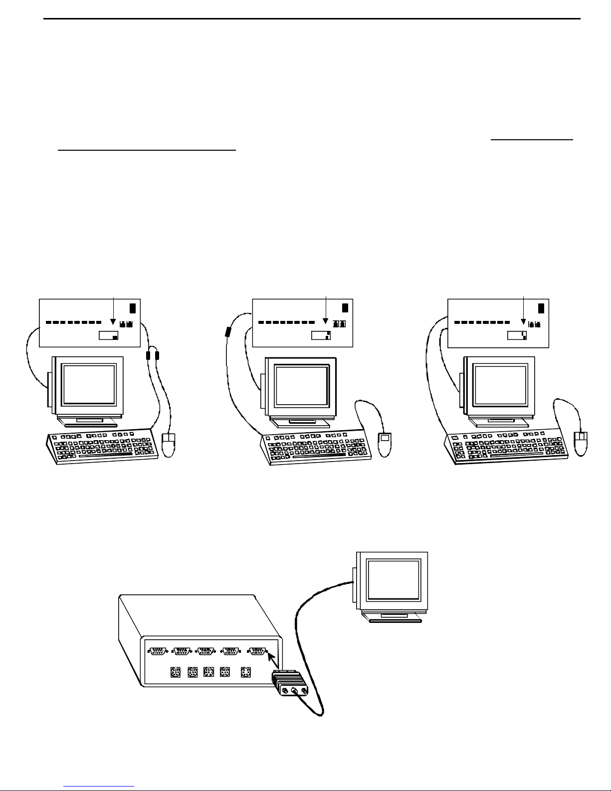
2. Configure the dip-switches for the type of keyboard and mouse being used (see Fig. 1). The dip-switches on the front panel
must be configured for the platform of the keyboard/mouse that will be used to operate the Universal switch. This action must be
completed prior to powering up the ST-xU. Should it be necessary to replace the keyboard of one platform with a keyboard of
a different platform, the dip-switches will need to be re-configured accordingly. To do this, first power-down the ST-xU by
following the proper power-down sequence. That is, turn the computers OFF first, then the NTI switch. When power has been
turned OFF, replace the keyboard, re-configure the switches and then power up, following the proper power-up sequence. That
is, turn ON power to the NTI Switch first, then to the computers. However, if the keyboard is being replaced with one from the
SAME PLATFORM, it can be hot-swapped without powering-down. Refer to the following diagrams for proper keyboard dipswitch configuration.
Fig. 1
Keyboard Dip-Switch Configuration
Switch 7 - OFF
Switch 8 - OFF
NETWORK
TECHNOLOGIES
NTI
INCORPORATED
ST-8U
12345678
ON
OFF
VGA
Multi-Scan
Monitor
PS/2 Keyboard & Mouse
VKTINT-1
MKTINT-1
NTI
ST-8U
Switch 7 - OFF
Switch 8 - ON
NETWORK
TECHNOLOGIES
INCORPORATED
12345678
ON
OFF
VGA
Multi-Scan
Monitor
MAC Keyboard / Mouse
EXISTING SUN
KEYBOARD/MOUSE
CABLE
NTI
ST-8U
NETWORK
TECHNOLOGIES
INCORPORATED
Switch 7 - ON
Switch 8 - OFF
12345678
ON
OFF
VGA
Multi-Scan
Monitor
3. If the Universal KVM switches are being cascaded together, configure the dip-switches accordingly (see Tables 1 and 2 on
page 8).
4. Connect the monitor to the port labeled MONITOR on the rear of the NTI Switch. (See Fig. 2.)
VGA
Multi-Scan
Monitor
VIDEO
VIDEO
PC-4
PC-3
KEY-4
KEY-3
(REAR VIEW)
VIDEO
PC-2
KEY-2 KEY-1
VIDEO
PC-1
MONITOR
KEYBD
Fig. 2
4
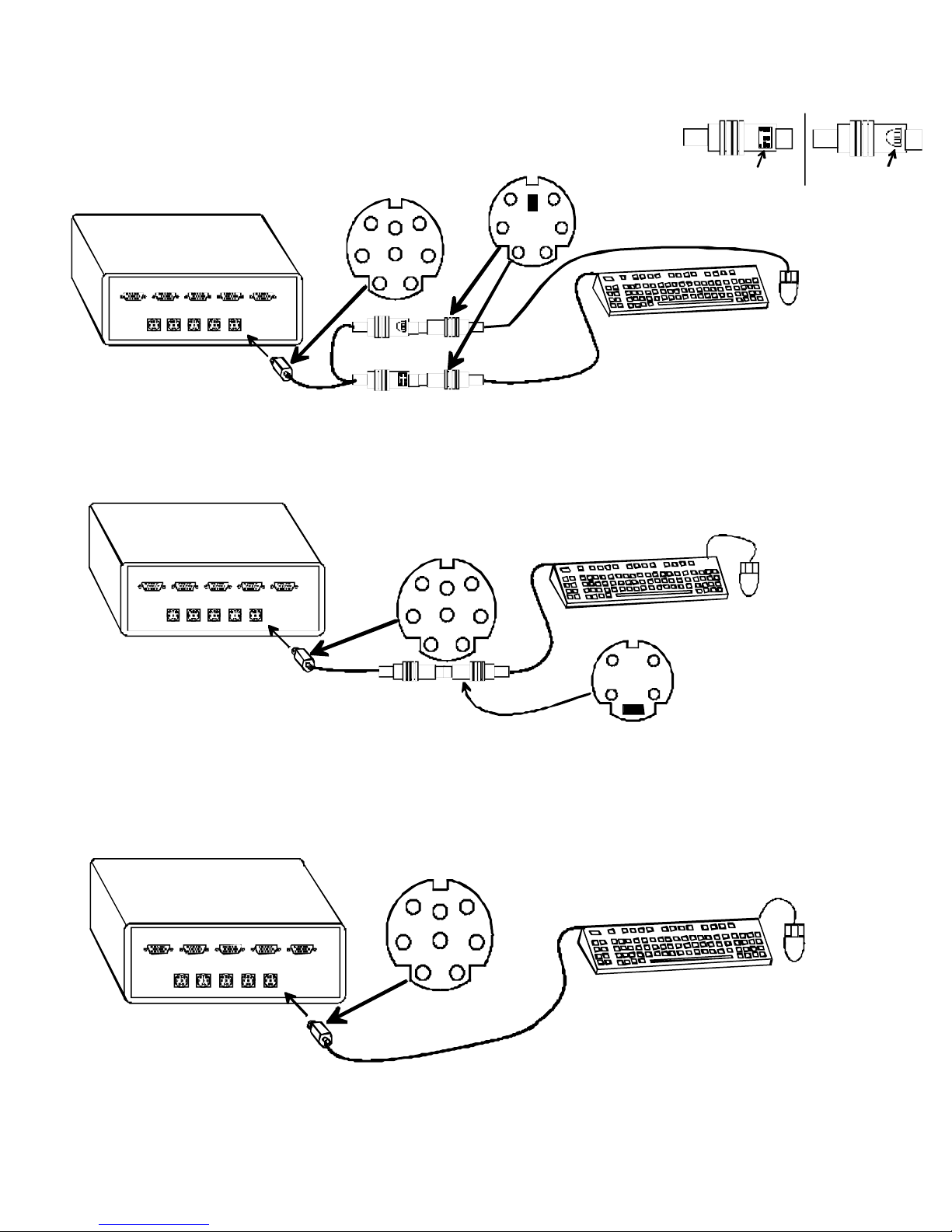
5. Connect the keyboard to the port labeled KEYBD on the rear of the NTI Switch following one of the methods detailed below:
A. If using a PS/2 keyboard, attach the 8-pin male end of a VKTINT-1 to the NTI switch at the KEYBD port. The keyboard
will plug into the 6-pin purple female connector with the keyboard symbol on it (see Fig. 3), and the mouse will plug into the 6-pin
green female connector with the mouse symbol on it (see Fig. 4).
VIDEO
PC-4
VIDEO
PC-3
KEY-3 KEY-2 KEY-1 KEYBDKEY-4
Fig. 5
VIDEO
PC-2
VIDEO
PC-1 MONITOR
VKTINT-1
8 Pin miniDIN Male
Connector
(GREEN)
(PURPLE)
6 Pin miniDIN Male
Connector
Keyboard Symbol Mouse Symbol
Fig. 3
PS/2 Keyboard
PS/2
Mouse
Fig. 4
B. If using a MAC keyboard/mouse, attach the 8-pin male end of a MKTINT-1 to the NTI switch at the KEYBD port. Attach
the keyboard/mouse assembly to the 4-pin female end of the MKTINT-1.
8 Pin miniDIN Male
Connector
VIDEO
VIDEO
VIDEO
PC-4
PC-3
KEY-3 KEY-2 KEY-1 KEYBDKEY-4
PC-2
VIDEO
PC-1
MONITOR
MAC Keyboard / Mouse
Fig. 6
MKTINT-1
C. If using a SUN keyboard/mouse, plug the SUN keyboard directly into the KEYBD port.
8 Pin miniDIN Male
Connector
VIDEO
VIDEO
VIDEO
PC-4
PC-3
KEY-3 KEY-2
PC-2
KEY-1
VIDEO
PC-1
KEYBDKEY-4
MONITOR
SUN Keyboard / Mouse
Fig. 7
4 Pin miniDIN Male
Connector
5
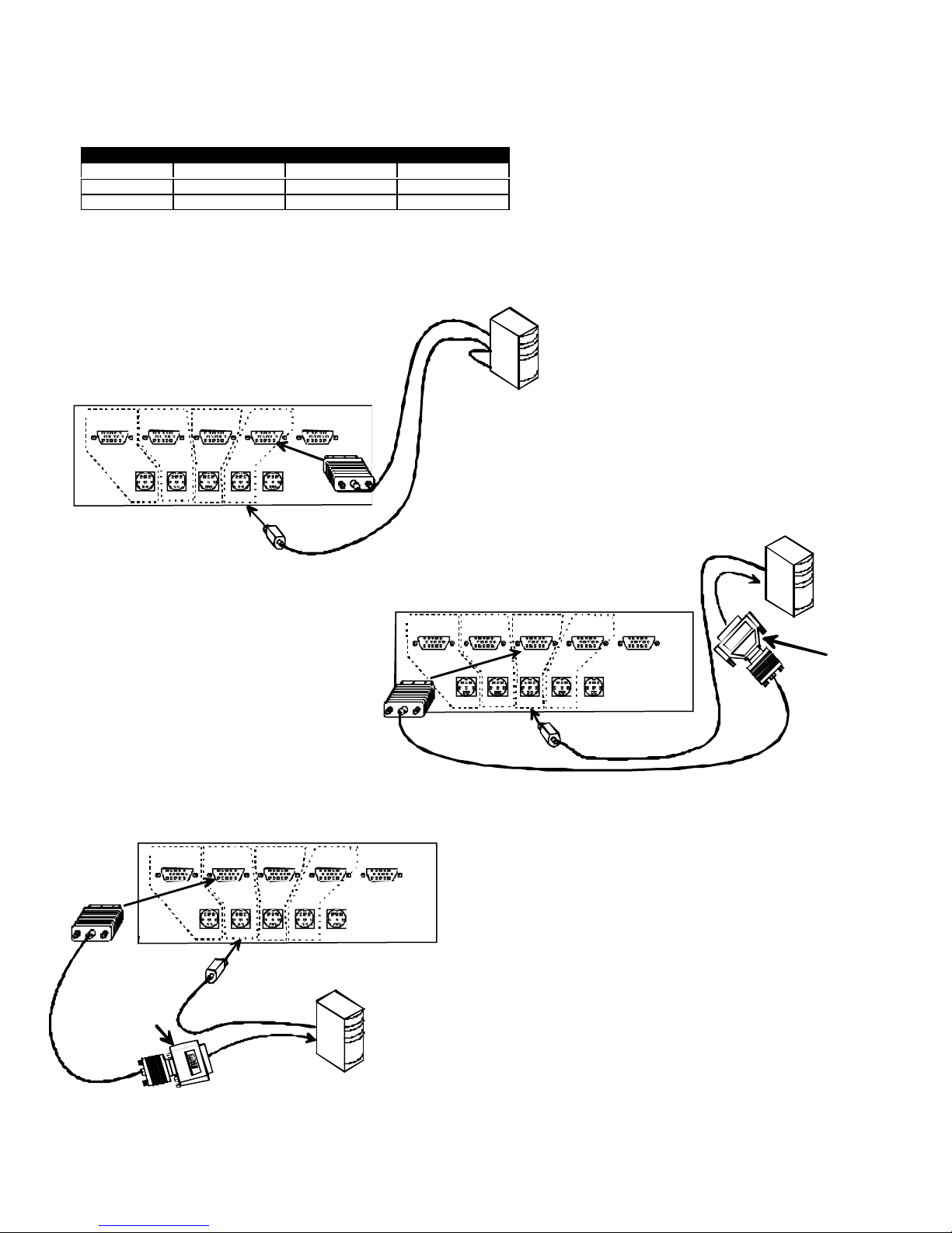
6. For each computer:
a. Connect the appropriate NTI universal adapter cable (see the chart below) from the keyboard port of the computer to a
keyboard port of the NTI Universal KVM switch (KEY-x). Note the port’s number. (See Fig. 8-10 below.)
b. Connect the appropriate NTI video cable (see the chart below) from the video port of the computer to the video port of the
NTI Universal KVM switch (VIDEO PC-x) with the same port number as the keyboard (see Fig. 8-10 below).
Computer Keyboard Cable Video Cable Video Adapter
PS/2 VKTINT-xx-MM VEXT-xx-MM None needed
MAC MKTINT-xx-MM VEXT-xx-MM 13W3M-15HDF
SUN SKTINT-xx-MM VEXT-xx-MM 15DM-15HDF
NOTE: Make sure the computer is connected to a keyboard port and a video port with the same number. Otherwise, the
commands typed to one computer may show up on the monitor intended for another computer.
Fig. 8
ATTACH FIRST COMPUTER TO PORT 1
(SHOWN HERE IS A PS/2 COMPUTER)
Port assignments ( ST-4U )
PORT 4 PORT 3 PORT 2 PORT 1
VIDEO
PC-4
VIDEO
PC-3
KEY-3 KEY-2 KEY-1 KEYBDKEY-4
VIDEO
PC-2
VIDEO
PC-1
Fig. 10
ATTACH A THIRD COMPUTER TO PORT 3
(SHOWN HERE IS A MAC COMPUTER)
PORT 4 PORT 3 PORT 2 PORT 1
VIDEO
PC-4
VIDEO
PC-3
VIDEO
PC-2
MONITOR
VIDEO
PC-1
VEXT-xx-MM
PORT 4 PORT 3 PORT 2 PORT 1
MONITOR
PS/2 COMPUTER
VKTINT-xx-MM
Fig. 9
ATTACH A SECOND COMPUTER TO PORT 2
(SHOWN HERE IS A SUN COMPUTER)
VIDEO
PC-4
VIDEO
PC-3
VIDEO
PC-2
KEY-3 KEY-2
VIDEO
PC-1
KEYBDKEY-4
KEY-1
SKTINT-xx-MM
MONITOR
SUN COMPUTER
13W3M-15HDF
VEXT-xx-MM
KEY-3 KEY-2 KEY-1 KEYBDKEY-4
VEXT-xx-MM
15DM-15HDF
MKTINT-xx-MM
MAC COMPUTER
6
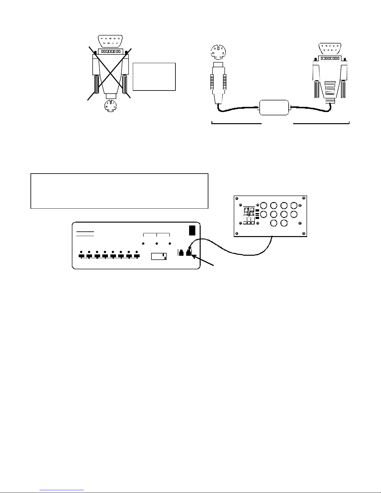
WARNING! If a serial mouse port is being used on a PC to connect a serial host to an NTI switch, do not use a generic 9D-to-
9D-to 6mD adapter
6mD adapter (Fig. 11) to make connection to the PS/2 cable-- use a VOPEX-IM9D (Fig. 12) to convert the signal from the serial
port to PS/2.
9D Male
6 Pin miniDIN
Male
9D Male
Do not use
with NTI
products
6 Pin miniDIN
Male
Generic
Fig. 11
VOPEX-IM9D
Fig. 12
7. Plug the NTI Universal KVM switch into an AC power outlet.
8. Connect the RMT (optional) to the NTI Switch “REMOTE IN” port using the REXT-SR-25 cable supplied with the RMT.
SPECIAL NOTE: Models ST-8U-R, ST-8U-R0, ST-4U-R, and
ST-4U-RO can only be installed as slaves in conjunction with a
Remote Control (RMT). These models will not support the direct
plug-in of the RMT.
ST-8U
NETWORK
TECHNOLOGIES
INCORPORATED
NTI
2 3 4 5 6 7 8
1
SCAN
1 2 3 4 5 6 7 8
ON
OFF
MODE
BROAD
CAST
COM
MAND
REMOTE REMOTE
OUT IN
RMT-SR
CPU CONNECTED
SCAN
BCAST CMD
RMT
N N
T T
I I
5162738
9
0
4
REMOTE IN
Fig. 13
9. Turn ON power to the NTI Universal KVM switch. (If multiple switches are being cascaded as described on page 7, switch
ON power to the slaves first, then the master.) The LED above button 1 on the front panel of the Universal KVM switch
should illuminate. If it doesn’t, see TROUBLESHOOTING.
Note: The NTI Universal KVM switch also supplies power to the optional RMT. See also SPECIAL NOTE above.
10. Turn ON power to any or all computers connected to the NTI Universal KVM switch.
Note: If upon startup the monitor immediately displays a USER LOGIN menu requiring a USER NAME and
PASSWORD, then the Administrator has already setup the system and enabled the OSD Security feature. Contact
the administrator for a login name and password. Then see page 12 for “USER LOGIN MODE” instructions.
 Loading...