

NTI SPLITMUX-SVDVI-2 Installation And Operation Manual
NTI
NETWORK
R
TECHNOLOGIES
INCORPORATED
1275 Danner Dr
Aurora, OH 44202
www.networktech inc.com
Tel:330-562-7070
Fax:330-562-1999
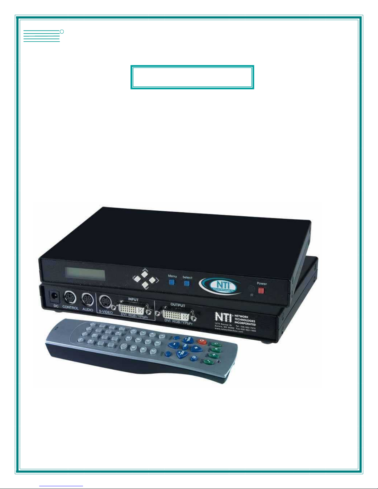
SPLITMUX®Series
SPLITMUX-SVDVI-2
Dual Screen Video Splitter
Installation and Operation Manual
Firmware Version 1.11 Rev 3122 and above
MAN009 Rev 1/16/08

SPLITMUX-SVDVI-2 DUAL SCREEN SPLITTER
TRADEMARK
SPLITMUX is a registered trademark of Network Technologies Inc in the U.S. and other countries.
COPYRIGHT
Copyright © 2007,2008 by Network Technologies Inc. All rights reserved. No part of this publication may be
reproduced, stored in a retrieval system, or transmitted, in any form or by any means, electronic, mechanical,
photocopying, recording, or otherwise, without the prior written consent of Network Technolo gies Inc, 1275 Danner
Drive, Aurora, Ohio 44202.
CHANGES
The material in this guide is for information only and is subject to change without notice. Network Technologies Inc
reserves the right to make changes in the product design without reservation and without notification to its users.
FIRMWARE VERSION
Firmware Version 1.11
i

SPLITMUX-SVDVI-2 DUAL SCREEN SPLITTER
TABLE OF CONTENT
1
INTRODUCTION ...................................................................................................................................1
2 ACCESSORIES.....................................................................................................................................3
2.1 OPTIONAL ACCESSORIES ..................................................................................................................4
3 IR REMOTE AND BASIC KEY FUNCTIONS .......................................................................................5
4 QUICK START GUIDE..........................................................................................................................6
5 LCD / KEYPAD......................................................................................................................................7
6 CONNECTIONS ....................................................................................................................................7
6.1 A/V & CONTROL CONNECTORS..........................................................................................................7
6.2 POWER CONNECTOR.........................................................................................................................8
6.3 EXAMPLES OF CONNECTIONS ............................................................................................................8
7 OPERATING THE SPLITMUX-SVDVI-2.............................................................................................11
7.1 REMOTE CONTROL FUNCTIONS .......................................................................................................11
7.2 MENU STRUCTURE..........................................................................................................................12
7.2.1 MAIN MENU.................................................................................................................................12
7.2.2 WINDOW SETUP..........................................................................................................................13
7.2.3 INPUT SETUP ..............................................................................................................................15
7.2.4 LAYOUT SETUP ...........................................................................................................................16
7.2.5 OUTPUT SETUP...........................................................................................................................17
7.2.6 SOUND SETUP ............................................................................................................................18
7.2.7 PRESET SETUP ...........................................................................................................................18
7.2.8 SYSTEM SETUP...........................................................................................................................19
8 SIGNAL TIMING..................................................................................................................................22
8.1.1 TIMER AND SCHEDULER...............................................................................................................22
9 VIDEO WALL FUNCTIONALITY ............................................................................................................25
10 REAL TIME IMAGE ROTATION...........................................................................................................27
11 TROUBLESHOOTING...........................................................................................................................28
12 RS-232 PROTOCOL........................................................................................................................29
13 SPECIFICATIONS...........................................................................................................................34
A. SUPPORTED VIDEO TIMING..............................................................................................................34
B. POWER SOURCE .............................................................................................................................35
C. CONNECTION TERMINALS.................................................................................................................35
D. DIMENSIONS...................................................................................................................................37
E. WEIGHT..........................................................................................................................................37
14 WARRANTY ....................................................................................................................................38
15 FCC PART 15 STATEMENT...........................................................................................................38
16 INDEX ..............................................................................................................................................39
ii
SPLITMUX-SVDVI-2 DUAL SCREEN SPLITTER
1 Introduction
The SPLITMUX-SVDVI-2 (SPLITMUX) is a high quality video processor engine. The
SPLITMUX-SVDVI-2 supports advanced functionality such as video format /scan rate
conversions, audio effects, real time image rotation (patents pending), and window effects. All
these can be controlled via IR remote and RS-232 commands. The device is small enough to fit
in tight areas. The progressive output(s) produces a high quality image using the latest 3:2 / 2:2
pull-down, motion handling, and noise reduction technologies.
•
•
Up to 165MHz bandwidth on the inputs and outputs.
Allows resolutions up to 1900 x 1200 @ 60Hz (narrow band sync) and can de-interlace
1080i to 1080p
Image enhancing capabilities including Motion Adaptive De-interlacing, Low-angle
Directional Interpolation, 3:2 & 2:2 inverse pull-down, Moiré cancellation, color correction,
adaptive flesh tone adjustments, image zoom & shrink.
•
•
•
•
The powerful Rotation / Picture-and-Picture (PAP) engine offers several modes of operation
including:
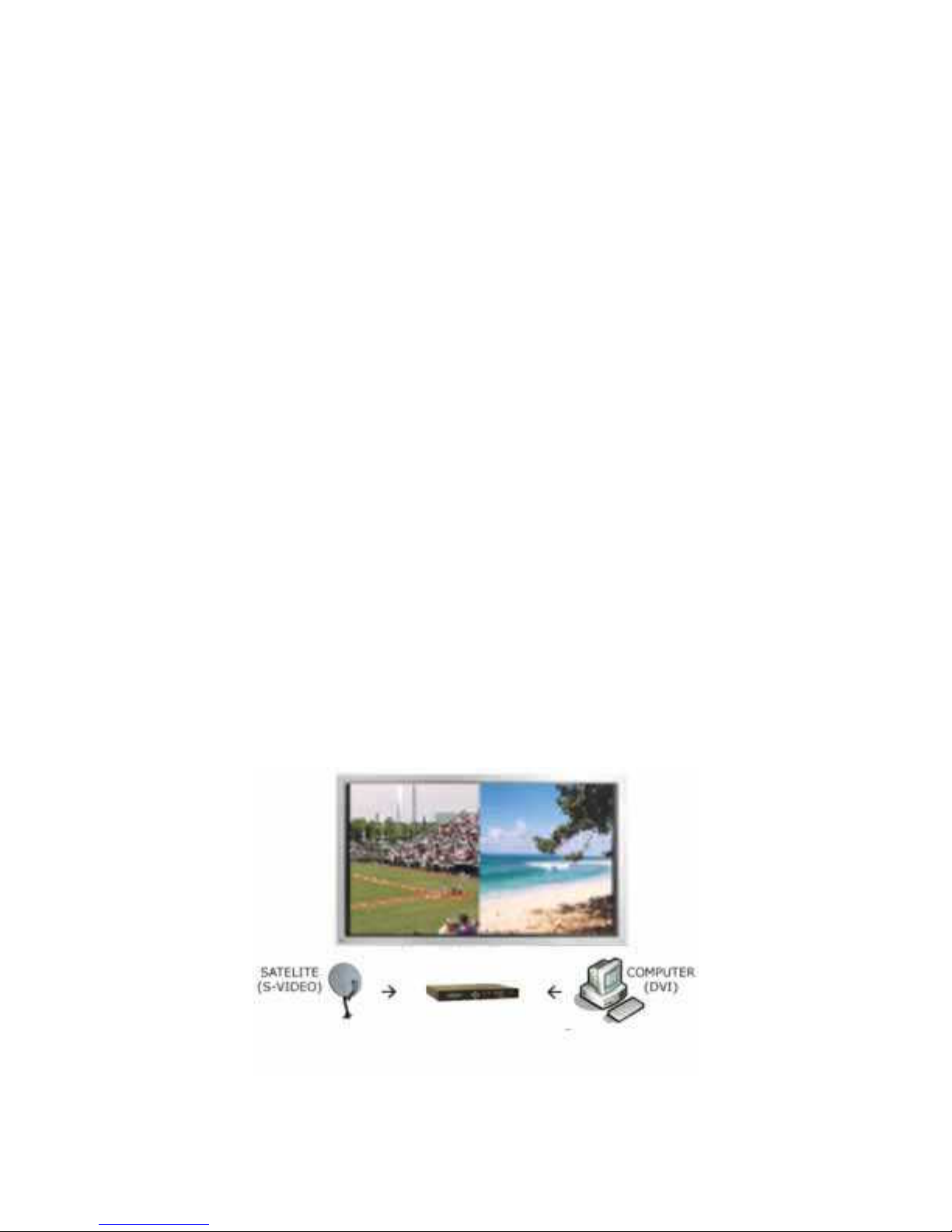
1. Hi-resolution Dual Image or Side-by-Side (split screen) images. Perfect for
teleconferencing, security, command and control applications.
2. Image Rotation (for digital signage)
3. Translucent Overlays to maximize main image size while still seeing PiP
Accepts digital and analog video inputs through a combination DVI/ RGBHV/ YPbPr
connectors and S-Video/Composite input connectors
Includes audio propagation delay compensation to properly sync with input video
Internal Event Scheduler with Real Time Clock allows Rotation Engine special effects to be
scheduled locally and among SPLITMUX units when connected via the RS-485 bus
Example Setup using the SPLITMUX side by side mode:
1

SPLITMUX-SVDVI-2 DUAL SCREEN SPLITTER
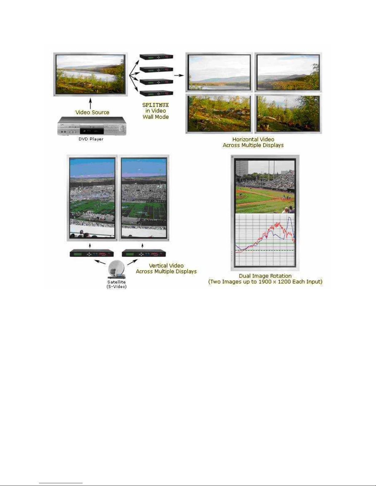
Just a few examples of the SPLITMUX’s capabilities:
Side by Side
Single with PiP Single with Translucent PiP
Single Rotated Dual Rotated
Single Rotated PiP Single Rotated Translucent PiP
Video Wall Mode Rotated Using 3 SPLITMUX Units
2
SPLITMUX-SVDVI-2 DUAL SCREEN SPLITTER
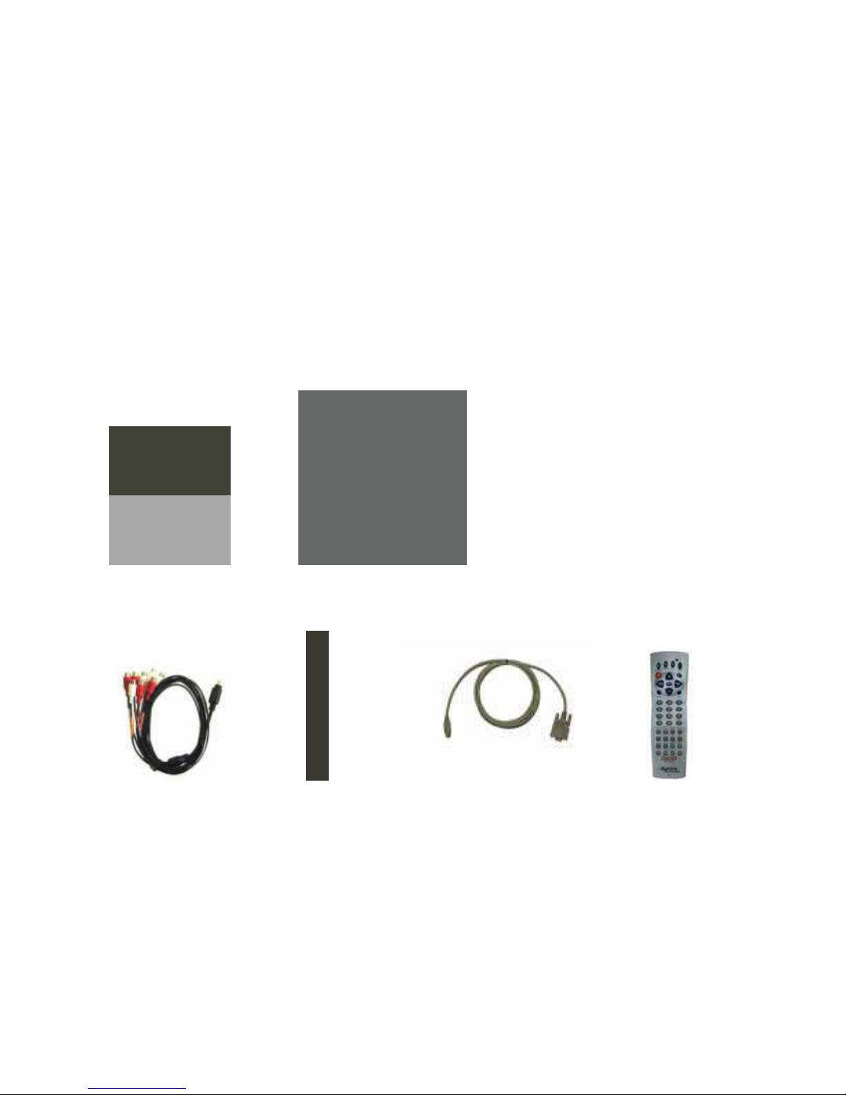
2 Accessories
Supplied accessories:
1 - 12V / 14.4W DC wall power supply or International Supply Kit if applicable
1 - 8 pin mini DIN to 8 RCA Female audio I/O cable
1 - S-Video to Composite Video Adaptors
1 - RS-232 Adaptor Cable (6 Pin Mini-Din to 9 Pin D-Sub)
1 - IR Remote
All supplied components are shown below:
12V / 15W Supply International Supply with Adaptors
Audio Breakout Cable S-Video to Video Adaptors RS-232 Control Cable IR Remote
3

SPLITMUX-SVDVI-2 DUAL SCREEN SPLITTER
2.1 Optional Accessories
Optional accessories available from NTI:
SPLITMUX-RS-S Single Rack Mount Kit
SPLITMUX-BOC-DVID15V SPLITMUX-BOC-DVID3RCA
DVI-I to DVI-D / VGA Breakout Cable DVI-I to DVI-D / RCA Breakout Cable
SPLITMUX-BOC-DVID5BNC SPLITMUX LOOP KIT RS-485
DVI-I to DVI-D / BNC Breakout Cable Loop Through Kit for connecting
multiple SPLITMUX units
4
SPLITMUX-SVDVI-2 DUAL SCREEN SPLITTER
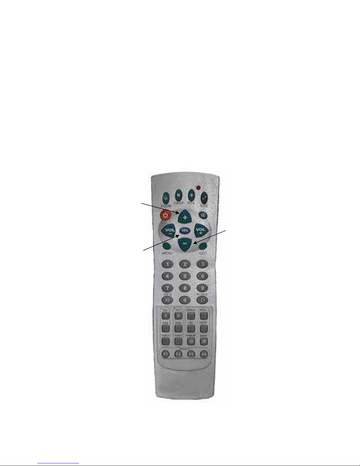
3 IR Remote and basic key functions
The SPLITMUX-SVDVI-2 can be controlled using an IR remote control, via the front panel, or
RS-232 commands. The remote is addressable for installing with multiple SPLITMUX units. To
change the address on the remote:
- Press and hold the ‘Up’ and ‘Down’ arrows together for 5 seconds. The red LED will
start to blink
- Enter the address (0-255) and press ‘Select’
In order for the IR remote to properly control a SPLITMUX, both devices (IR remote and the
SPLITMUX) have to have the same address. See System Setup Menu (pg. 18) for more
information on how to change the SPLITMUX’s address.
Up Arrow
Select
Down Arrow
5

SPLITMUX-SVDVI-2 DUAL SCREEN SPLITTER
For details of SPLITMUX-SVDVI-2 operation, refer to the corresponding chapter of this
document.
Below is a brief description of the remote transmitter and the keys used for SPLITMUX control.
IR Remote Function
POWER Toggles Power On and Off
ZOOM Brings up Zoom selection for each wind ow 0-100%
CROP Brings up Crop selection for each window 0-100%
POS Brings up Position selection for each window 0-100%
SIZE Brings up Size selection for each window 0-100%
VOLUME + Increases Volume level
VOLUME - Decreases Volume level
MUTE Toggles the volume Mute On/Off
ARROWS Moves the cursor up/down/left/right when Menu is active
MENU Displays Main Menu
SEL Selects option in Menu
Finishes input in dialog panels
EXIT Exits 1 menu level
0..9, DIGITS Enters digits when dialog menu is active.
INFO Displays current input/output timings and FW version
ROTATE Rotates output image by 0, 90, 180, 270 degrees
DVI A Selects DVI Side A Input
RGB A Selects RGB/YPbPr Input
VIDEO A Selects Video/S-Video Input
DVI B Not Available for SPLITMUX-SVDVI-2
RGB B Not Available for SPLITMUX-SVDVI-2
VIDEO B Not Available for SPLITMUX-SVDVI-2
SINGLE Selects 1 window on the output
DUAL Selects 2 windows on the output
TRI Not Available for SPLITMUX-SVDVI-2
QUAD Not Available for SPLITMUX-SVDVI-2
SWAP Swaps the sources between the windows
FREEZE Freezes the current window
PRESET KEYS P1 – P4 selects the stored preset
4 Quick Start Guide
1. Make sure the SPLITMUX and the Display are both disconnected from power.
2. Connect the SPLITMUX to the Display’s DVI, VGA, or YPbPr port as required.
3. Connect the appropriate video sources to input connectors of SPLITMUX (see
“Connections” chapter (pg. 7) for details).
4. Connect audio input/output to the 8-pin miniDIN connector of the SPLITMUX (see
“Connections” chapter (pg. 7) for details).
5. Connect the power source to the Display (refer to Operating Instructions of the Display).
6. Connect the supplied 12v DC adapter to the SPLITMUX and the power outlet. The LCD
will illuminate and after 5 seconds, the firmware rev will appear. About 15 seconds
later, the SPLITMUX will complete initialization and display the output resolution and
format on the LCD. The last settings of the SPLITMUX will take effect.
6
SPLITMUX-SVDVI-2 DUAL SCREEN SPLITTER
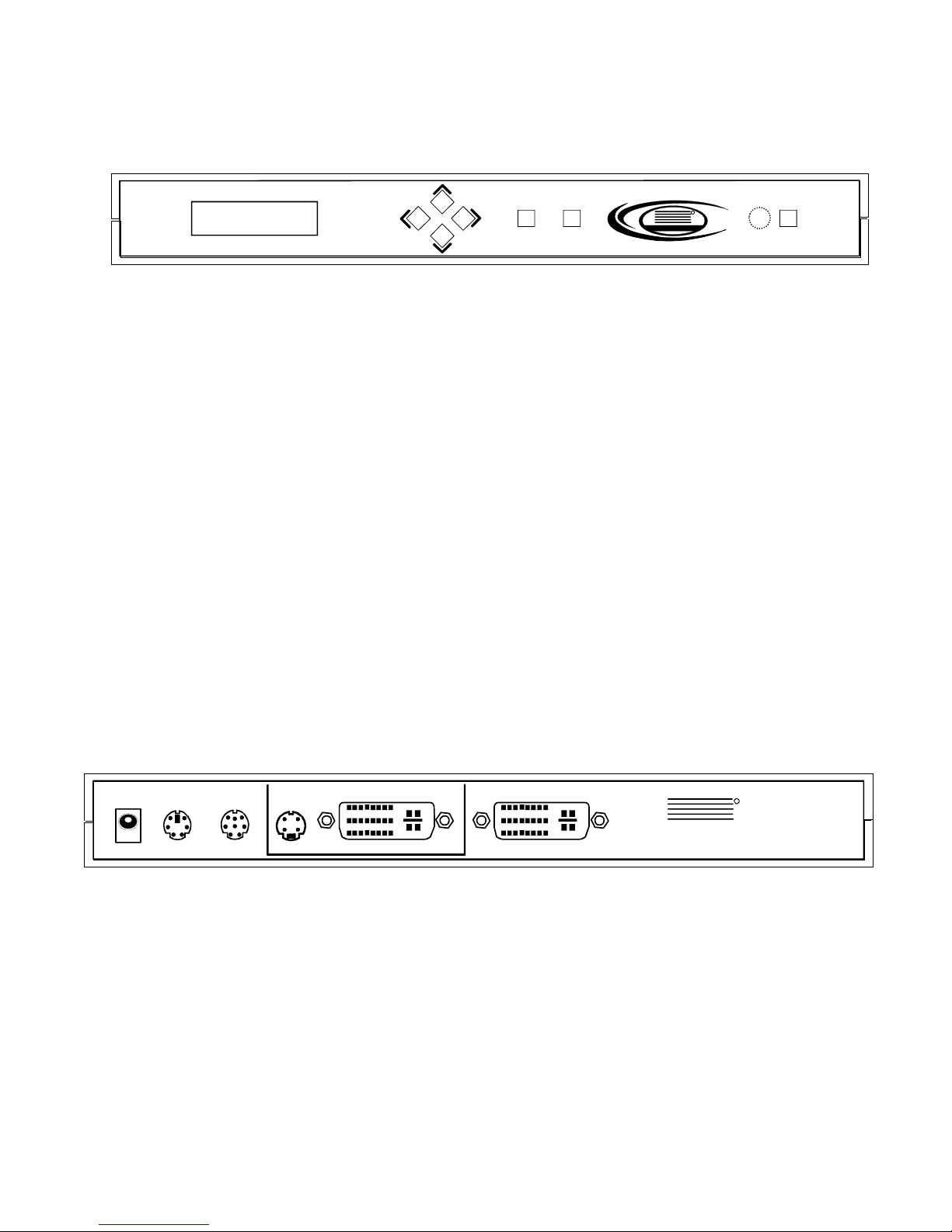
5 LCD / Keypad
Menu Select Power
NTI
Network Technologies Inc
R
IR
The LCD helps to navigate through menus with the front keypad.
- Menu: brings up the menu on the screen and the LCD - exits menu levels.
- Select: brings up next menu level or confirms an entry.
- Arrows: navigate through the menus and change selections.
- Power: Toggles the Power ON and OFF. This button can also be used to restore all
Default values if it’s held down for 10 seconds when the power connector is
first applied. Factory default for the output is RGBHV XGA 60Hz.
- Presets: Holding the select key and pressing the up arrow key will trigger preset 1,
right is preset 2, down is preset 3, and left is preset 4. (See Preset Setup on
pg. 17)
Note: Restoring default values will delete all saved settings.
When no OSD (Menu) is present, the ‘Up’ and ‘Down’ arrow keys will show the status of
different functions such as output resolution, layout, input source, etc. The ‘Right’ and ‘Left’
arrow keys can be used to scroll the text that can not otherwise be seen on the LCD.
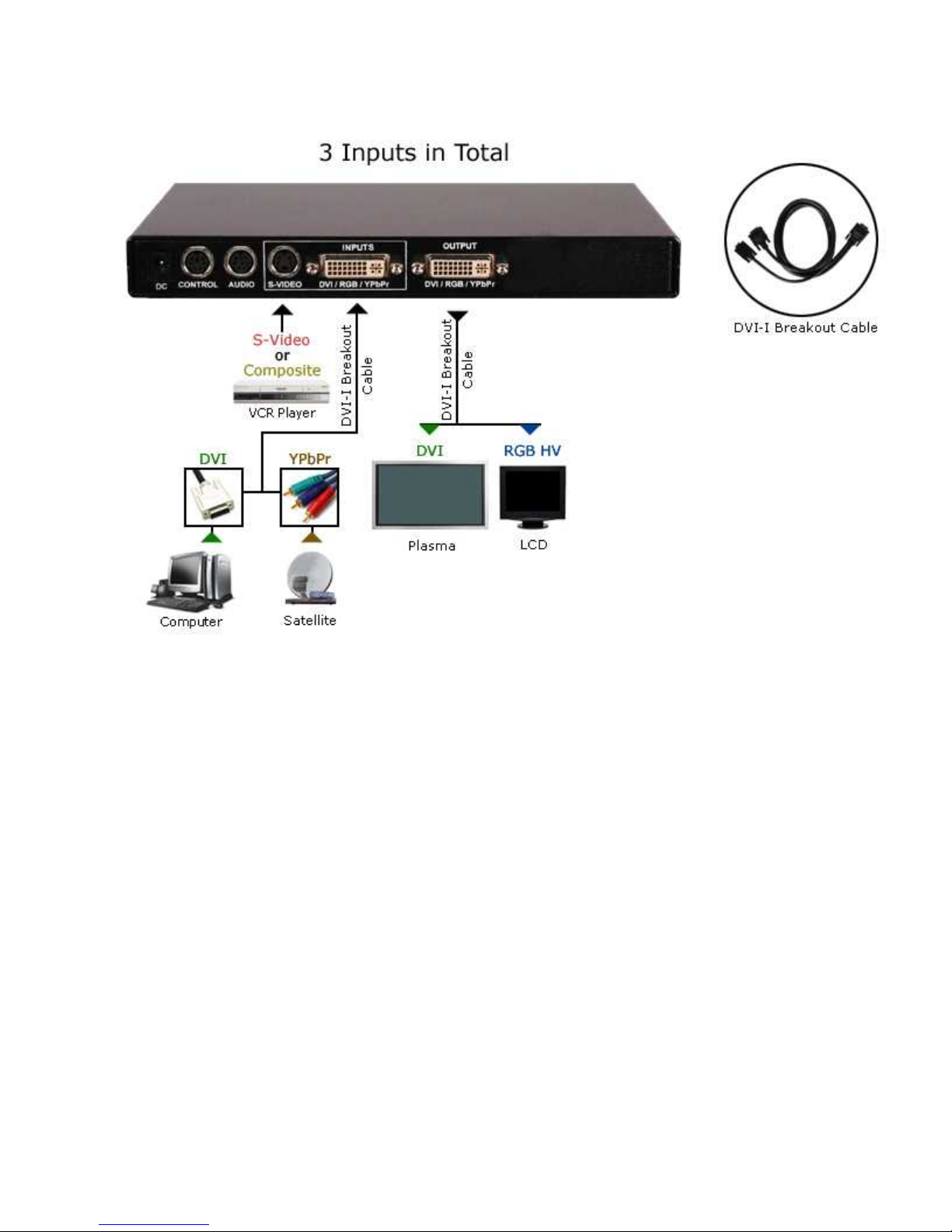
6 Connections
The SPLITMUX has 3 independent inputs and 2 outputs. In addition, there is an audio
INPUT/OUTPUT port and an RS-232 CONTROL port.
INPUT OUTPUT
DC
S-VIDEOAUDIOCONTROL DVI RGB/YPbPr DVI RGB/YPbPr
6.1 A/V & Control connectors
• CONTROL (6-pin mini DIN): RS-232 connection and RS-485 loop-through to control
multiple SPLITMUX units.
• AUDIO (8-pin mini DIN): for use with supplied audio breakout cable .
• S-VIDEO (4-pin mini DIN): S-Video or Composite (supplied adaptor) input.
• DVI/RGB/YPbPr: for hi-res inputs. If a DVI-I breakout cable is used (see
“Optional Accessories” page 4), RGBHV/YPbPr can be input as an additional
source to the DVI.
NTI
1275 Danner Dr
Aurora, OH 44202
www.networktechinc.com
R
NETWORK
TECHNOLOGIES
INCORPORATED
Tel:330-562-7070
Fax:330-562-1999
7

SPLITMUX-SVDVI-2 DUAL SCREEN SPLITTER
• DVI/RGB/YPbPr OUTPUT for hi-res outputs. If a DVI-I breakout cable is used (see
“Optional Accessories” page 4), RGBHV/YPbPr can be output in addition to the
DVI.
The supplied audio input/output adapter cable has labels on cables near RCA connectors.
These labels indicate the purpose of each RCA connector. They are:
¾ Side A Left Audio / SPDIF A,
¾ Side A Right Audio,
¾ Side B Left Audio,
¾ Side B Right Audio,
¾ Line Out Left / SPDIF Out,
¾ Line Out Right
The respective audio input channels (A or B) are selected from the menu or RS-232 command.
6.2 Power connector
Connect the supplied 12V DC adapter to the power jack of the SPLITMUX. It is recommended
to connect the power supply only after all other connections are done.
6.3 Examples of Connections
8
SPLITMUX-SVDVI-2 DUAL SCREEN SPLITTER
9
SPLITMUX-SVDVI-2 DUAL SCREEN SPLITTER
10
 Loading...