

NTI SPLITMUX-HD-4RT, SPLITMUX-HD-4RT-R Installation And Operation Manual
R
®
SPLITMUX
Series
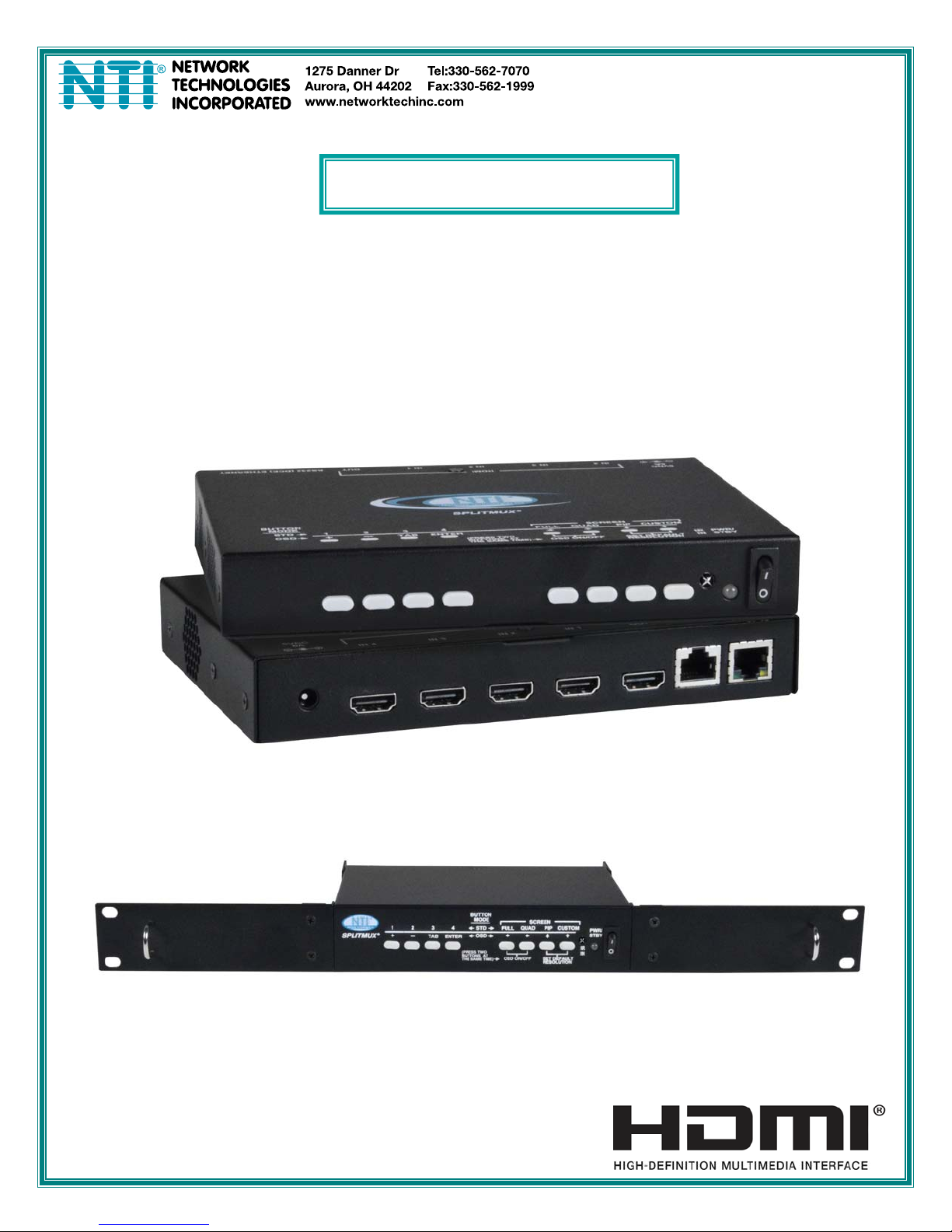
SPLITMUX-HD-4RT
Quad Screen Video Splitter
Installation and Operation Manual
SPLITMUX-HD-4RT
SPLITMUX-HD-4RT-
MAN225 Rev Date 3/30/15

SPLITMUX Quad Screen Video Splitter
TRADEMARK
SPLITMUX is a registered trademark of Network Technologies Inc in the U.S. and other countries.
COPYRIGHT
Copyright © 2014,2015 by Network Technologies Inc. All rights reserved. No part of this publication may be
reproduced, stored in a retrieval system, or transmitted, in any form or by any means, electronic, mechanical ,
photocopying, recording, or otherwise, without the prior written consent of Network Technologies Inc, 127 5 Danner
Drive, Aurora, Ohio 44202.
CHANGES
The material in this guide is for information only and is subject to change without notice. Network Technologies Inc
reserves the right to make changes in the product design without reservation and without notification to its users.
FIRMWARE VERSION
1.3
WARRANTY INFORMATION
The warranty period on this product (parts and labor) is two (2) years from the date of purchase. Please contact
Network Technologies Inc at (800) 742-8324 (800-RGB-TECH) or (330) 562-7070 or visit ou r website at
http://www.networktechinc.com for information regarding repairs and/or returns. A return authori zation n umber is
required for all repairs/returns.
i

SPLITMUX Quad Screen Video Splitter
TABLE OF CONTENTS
Introduction......................................................................................................................................................................1
Supported Web Browsers ...............................................................................................................................................2
Materials..........................................................................................................................................................................2
Connectors and LEDs.....................................................................................................................................................3
Mounting..........................................................................................................................................................................4
Single-SPLITMUX mounting........................................................................................................................................5
Dual-SPLITMUX mounting ..........................................................................................................................................6
Reversible Mounting Assembly ................................................................................................................................7
Installation .......................................................................................................................................................................8
Terminal Connection for RS232..................................................................................................................................8
Ethernet Connection for Remote User Control............................................................................................................9
Power ON......................................................................................................................................................................10
Control Methods............................................................................................................................................................10
Front Panel Buttons...................................................................................................................................................10
Standard Mode .......................................................................................................................................................10
OSD Mode..............................................................................................................................................................12
Reset Resolution .................................................................................................................................................12
Device Discovery Tool...................................................................................................................................................13
How to Use the Device Discovery Tool.....................................................................................................................13
Use and Operation via Web Interface...........................................................................................................................14
Log In and Enter Password .......................................................................................................................................14
Administration-System............................................................................................................................................16
Administration-Network...........................................................................................................................................18
Administration- Input Settings.................................................................................................................................19
Administration- Output Settings..............................................................................................................................20
Audio Level and Gain..........................................................................................................................................21
Audio Mode Settings ...........................................................................................................................................21
Administration-Mode Settings.................................................................................................................................22
Administration- Custom Settings ............................................................................................................................24
Preset Layouts and Display Preview...................................................................................................................25
Alignment Tools...................................................................................................................................................25
Channel Settings.................................................................................................................................................26
Enable/Disable Channels....................................................................................................................................26
Save/Restore Layouts.........................................................................................................................................27
Cascade Settings....................................................................................................................................................28
Administration-User Config.....................................................................................................................................30
Administration- Firmware........................................................................................................................................31
Administration- System Information........................................................................................................................32
Logout........................................................................................................................................................................32
Support ......................................................................................................................................................................33
Reboot .......................................................................................................................................................................33
Command Line Interface...............................................................................................................................................34
RS232 Control...........................................................................................................................................................34
Baud Rate............................................................................................................................................................34
Unit Address and Loop Back...............................................................................................................................34
RS232 Command Protocol.....................................................................................................................................35
Telnet Control............................................................................................................................................................36
ii

SPLITMUX Quad Screen Video Splitter
Using The Text Menu....................................................................................................................................................37
Text Menu Navigation..........................................................................................................................................37
Current Mode.............................................................................................................................................................38
System Configuration ................................................................................................................................................39
Network Configuration...............................................................................................................................................41
User Configuration.....................................................................................................................................................43
Input Configuration ....................................................................................................................................................45
Output Configuration..................................................................................................................................................46
Mode Configuration ...................................................................................................................................................48
Load/Save Layout......................................................................................................................................................51
System Information....................................................................................................................................................52
Using OSD.....................................................................................................................................................................53
Navigating the OSD menus....................................................................................................................................53
System Configuration ................................................................................................................................................54
Network Configuration...............................................................................................................................................55
Input Configuration ....................................................................................................................................................57
Output Configuration..................................................................................................................................................58
Mode Configuration ...................................................................................................................................................59
Load / Save Layout....................................................................................................................................................62
System Information....................................................................................................................................................63
Infrared Remote Control................................................................................................................................................64
Materials ....................................................................................................................................................................64
Buttons.......................................................................................................................................................................64
Operation...................................................................................................................................................................64
Changing Ports.......................................................................................................................................................64
Save and Recall......................................................................................................................................................65
Multiple Switch Control...........................................................................................................................................65
Technical Specifications For IRT-UNV......................................................................................................................65
Troubleshooting the IRT-UNV ...................................................................................................................................65
Example of Cascaded Configuration.............................................................................................................................66
Specifications ................................................................................................................................................................69
Index..............................................................................................................................................................................69
Figure 1- Attach ear brackets to front corners or rear corners...........................................................................................................4
Figure 2- Attach cable tray (if applicable)...........................................................................................................................................4
Figure 3- Attach rack ears..................................................................................................................................................................5
Figure 4- Assembled unit, ready to mount in rack..............................................................................................................................5
Figure 5- Attach ears and connector plate.........................................................................................................................................6
Figure 6- Attach cable tray connector................................................................................................................................................6
Figure 7- Assembly method for SPLITMUX with cables facing forward.............................................................................................7
Figure 8- Assembled SPLITMUX-HD-4RT-2R...................................................................................................................................7
Figure 9- Video Source/Display Connections ....................................................................................................................................8
Figure 10- RS232 Terminal Connection.............................................................................................................................................8
Figure 11- Ethernet connection..........................................................................................................................................................9
Figure 12- Front Panel Button Functions.........................................................................................................................................12
Figure 13- Device Discovery Tool....................................................................................................................................................13
TABLE OF FIGURES
iii

SPLITMUX Quad Screen Video Splitter
Figure 14- Login prompt to access web interface............................................................................................................................14
Figure 15- Initial page- Administrator...............................................................................................................................................15
Figure 16- Initial page- Non-Admin User..........................................................................................................................................15
Figure 17- System Configuration.....................................................................................................................................................16
Figure 18- Network Configuration....................................................................................................................................................18
Figure 19- Input Settings..................................................................................................................................................................19
Figure 20- Output Settings...............................................................................................................................................................20
Figure 21- Display with sound level indications ...............................................................................................................................21
Figure 22- Mode Settings.................................................................................................................................................................22
Figure 23- PIP Screen Mode Settings .............................................................................................................................................23
Figure 24- Custom Screen Mode Settings.......................................................................................................................................24
Figure 25- Pan and Crop Enabled...................................................................................................................................................25
Figure 26- Cascading SPLITMUXs..................................................................................................................................................28
Figure 27- Cascade Settings ...........................................................................................................................................................28
Figure 28- User Configuration..........................................................................................................................................................30
Figure 29- Firmware Update............................................................................................................................................................31
Figure 30- System Information page................................................................................................................................................32
Figure 31- RS232 connection with Matrix-Y-1 cable........................................................................................................................35
Figure 32- Pinout of Matrix-Y-1 cable ..............................................................................................................................................35
Figure 33- Text Menu- Login screen................................................................................................................................................37
Figure 34- Text Menu-Main Menu....................................................................................................................................................38
Figure 35- Text Menu-Current Mode Selection ................................................................................................................................38
Figure 36- Text Menu- System Configuration..................................................................................................................................39
Figure 37- Text Menu- Unit Settings................................................................................................................................................39
Figure 38- Text Menu- Serial Port Settings......................................................................................................................................40
Figure 39- Text Menu- OSD Screen Settings ..................................................................................................................................40
Figure 40- Text Menu- Restore Default Settings..............................................................................................................................41
Figure 41- Text Menu- Network Configuration.................................................................................................................................41
Figure 42-Text Menu- IPv4 Network Settings..................................................................................................................................42
Figure 43- Text Menu-Server Settings.............................................................................................................................................43
Figure 44- Text Menu- Users List ....................................................................................................................................................43
Figure 45- Text Menu- Account Settings..........................................................................................................................................44
Figure 46- Text Menu- User Account Settings.................................................................................................................................44
Figure 47- Text Menu- Input Configuration......................................................................................................................................45
Figure 48- Text Menu- Output Configuration ...................................................................................................................................46
Figure 49- Text Menu- Audio Output Configuration.........................................................................................................................47
Figure 50- Text Menu- Mode Settings Menu....................................................................................................................................48
Figure 51- Text Menu- Default Mode Configuration.........................................................................................................................48
Figure 52- Text Menu- Full Screen Mode Settings ..........................................................................................................................49
Figure 53- Text Menu- Quad Mode Settings....................................................................................................................................49
Figure 54- Text Menu- PIP Mode Settings .......................................................................................................................................50
Figure 55- Text Menu- Custom Mode Settings................................................................................................................................51
Figure 56- Text Menu- Load/Save Layout........................................................................................................................................51
Figure 57- Text Menu- System Information......................................................................................................................................52
Figure 58- Front Panel Button OSD Functions ................................................................................................................................53
Figure 59- The OSD Menu...............................................................................................................................................................53
Figure 60- OSD System Configuration.............................................................................................................................................54
Figure 61- OSD Network Configuration ...........................................................................................................................................55
Figure 62- OSD IP Settings .............................................................................................................................................................56
Figure 63- OSD Server Settings......................................................................................................................................................56
Figure 64- OSD Input Configuration ................................................................................................................................................57
Figure 65- OSD Input Settings.........................................................................................................................................................57
Figure 66- OSD Output Settings......................................................................................................................................................58
Figure 67- OSD Mode Settings........................................................................................................................................................59
iv

SPLITMUX Quad Screen Video Splitter
Figure 68- Default, Full Screen and Quad Screen Settings.............................................................................................................60
Figure 69- PIP Screen Mode settings.............................................................................................................................................. 61
Figure 70- OSD- Custom Screen Mode Settings.............................................................................................................................62
Figure 71- Save or Load a Custom Layout......................................................................................................................................63
Figure 72- OSD- System Information Page .....................................................................................................................................63
Figure 73- View of cascaded configuration from Master..................................................................................................................66
Figure 74- View of cascaded configuration from Slave at IP 192.168.3.173....................................................................................67
Figure 75- View of cascade configuration from Slave at IP 192.168.3.125......................................................................................67
Figure 76- View of custom configuration of Slave at IP 192.168.3.183............................................................................................68
Figure 77- Current output mode selection........................................................................................................................................68
v

SPLITMUX Quad Screen Video Splitter
INTRODUCTION
The SPLITMUX® HD Quad Screen Multiviewer allows you to simultaneously display video from four different computers or video
sources on a single monitor providing resolutions up to 1920 x 1200.
Features:
• Quad, Picture in Picture, Full Screen, and Custom display modes.
• Independent video in to video out resolution.
• Supports HDTV resolutions to 1080p and computer resolutions to 1920x1200.
• Connect digital sources to the splitter and display images on a digital monitor.
• HDMI features supported:
o Inputs: 24-, 30-, and 36-bit xvYCC, sRGB, and YCbCr.
o Outputs: 24- and 30-bit sRGB.
o Four-channel non-mixing or one-channel mixing stereo with 16-, 20-, or 24-bit uncom pressed PCM audio.
o Bandwidth up to 165 MHz (2.0625 Gbps).
• Any DVI source or display can be connected by using the DVI-HD-xx-MM cable (not included).
o Use DVIA-HD-CNVTR-LC or DVI-HD-CNVTR DVI + Audio to HDMI Converters to pass and independently
switch audio signals to the multiviewer.
• Supports digital DVI (with DVI-HD-xx-MM cables, not included) and HDMI.
• HDCP compliant
• On-screen display
• Fluid, real-time video performance with 60 frames per second (fps) in all four quadrants
• Switch audio independently of video from HDMI sources
• Control the multiviewer through the front panel buttons, on screen display (OSD), RS232 serial port, infrared remote
control or Ethernet.
• HDMI-embedded audio switching (four-channel stereo, non-mixing or one-channel stereo, mixing).
• Backup and restore multiviewer configuration.
• Select default EDID or copy EDID from output monitor.
o Supported output resolutions can be selected or set to auto detect.
• Available options: desktop unit, 1RU rackmount unit, dual side-by-side rackmount units in 1RU.
o Rackmount units can be mounted so that the front panel buttons are facing the front or back of the rack.
o Rackmount units include cable management shelf.
1

SPLITMUX Quad Screen Video Splitter
SUPPORTED WEB BROWSERS
Most modern web browsers should be supported. The following browsers have been tested:
• Microsoft Internet Explorer 8.0 or higher
• Mozilla FireFox 30.0 or higher
• Opera 12.02 or higher
• Google Chrome 9.0.5 or higher
• Safari 5.0 or higher for MAC and PC
MATERIALS
Materials supplied with this kit:
• NTI SPLITMUX-HD-4RT Multiviewer
• 1- 120VAC or 240VAC at 50 or 60Hz-5VDC/3A AC Adapter (PS4191)
• CT6182 DB9 Female-to-RJ45 Female adapter
• CB7094 5 foot CAT5E-SF32-5-BLACK patch cable
• CT7003 IR Remote Control with two (2) AAA batteries (PS0154)
• CD containing a pdf of this manual and the NTI Discovery Tool
Additional Materials Included with SPLITMUX-HD-4RT-R (same as SPLITMUX-HD-4RT plus the following):
2- MP4829 Ear Brackets
2- MP4826 Long Rack Ears
1- MP4825 Cable Tray
12- HW5133 #6-32x1/4” Flat head Screws
Materials Included with SPLITMUX-HD-4RT-2R (same as SPLITMUX-HD-4RT plus the following):
6- MP4829 Ear Brackets
2- MP4827 Short Rack Ears
1- MP4830 Cable Tray Connector
2- MP4828 Connector Plate
2- MP4825 Cable Tray
28- HW5133 #6-32x1/4” Flat head Screws
Additional materials may need to be ordered;
CAT5/5e/6 unshielded twisted-pair cable(s) terminated with RJ45 connectors wired straigh t thru- pin 1 to pin 1, etc. for Ethernet
connection
Contact your nearest NTI distributor or NTI directly for all of your cable needs at 800-RGB-TECH (800-742-8324) in US & Canada
or 330-562-7070 (Worldwide) or at our website at http://www.networktechinc.com
and we will be happy to be of assistance.
2
SPLITMUX Quad Screen Video Splitter
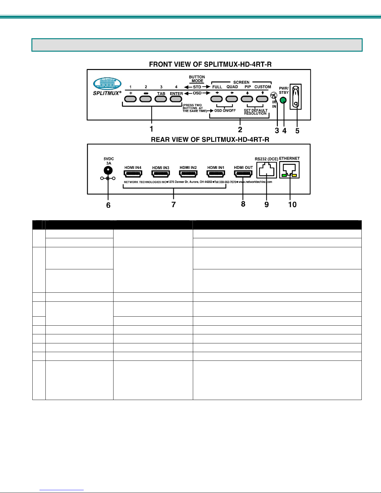
CONNECTORS AND LEDS
#
LABEL CONNECTOR/LED DESCRIPTION
1-4
1
+, -, TAB, ENTER
SCREEN-
2
FULL,QUAD,PIP,MODE
(Display Modes)
Directional Arrows
3 IR IN
4
PWR/STBY
5
6 5VDC 3A
7 HDMI IN1-4
8 HDMI OUT
9 RS232 (DCE)
10 ETHERNET
Pushbuttons
Pushbuttons
IR Sensor Input sensor to receive IR signals from remote control
Green/Red LED To indicate when the SPLITMUX is powered ON (Green) or in
Rocker switch For switching the SPLITMUX between ON (I) and Standby (O)
2.1x5.5mm Power Jack For connection of power supply
HDMI female connector For connection of HDMI video sources
HDMI female connector For connection of cable to HDMI Monitor
RJ45 female connector For RS232 serial connection of a terminal to control the system
RJ45 female connector For connection to an Ethernet for remote multi-user control
HDMI Input Selection (Standard Mode)
OSD Menu Navigation (OSD Mode)
For selecting the display mode for image placement on the user’s
monitor
Used for OSD Menu Navigation
Also used to toggle the OSD Menu ON/OFF and returning the
SPLITMUX to the default display resolution
Standby (Red)
• Yellow LED- indicates 100Base-T activity when illuminated,
10Base-T activity when dark
• Green LED – illuminated when Ethernet link is present,
strobing indicates activity on the Ethernet port
3
SPLITMUX Quad Screen Video Splitter
MOUNTING
The SPLITMUX-HD-4RT can be purchased in a 1RU case with parts and hardware for mounting in a rack as a single unit
(SPLITMUX-HD-4RT-R) or as a dual unit (SPLITMUX-HD-4RT-2R). Follow the instructions below for assembly and installation.
Whether the SPLITMUX will be mounted as a single or a double, brackets will be attached to the case to enable moun ting ears or
a connector plate to be attached.
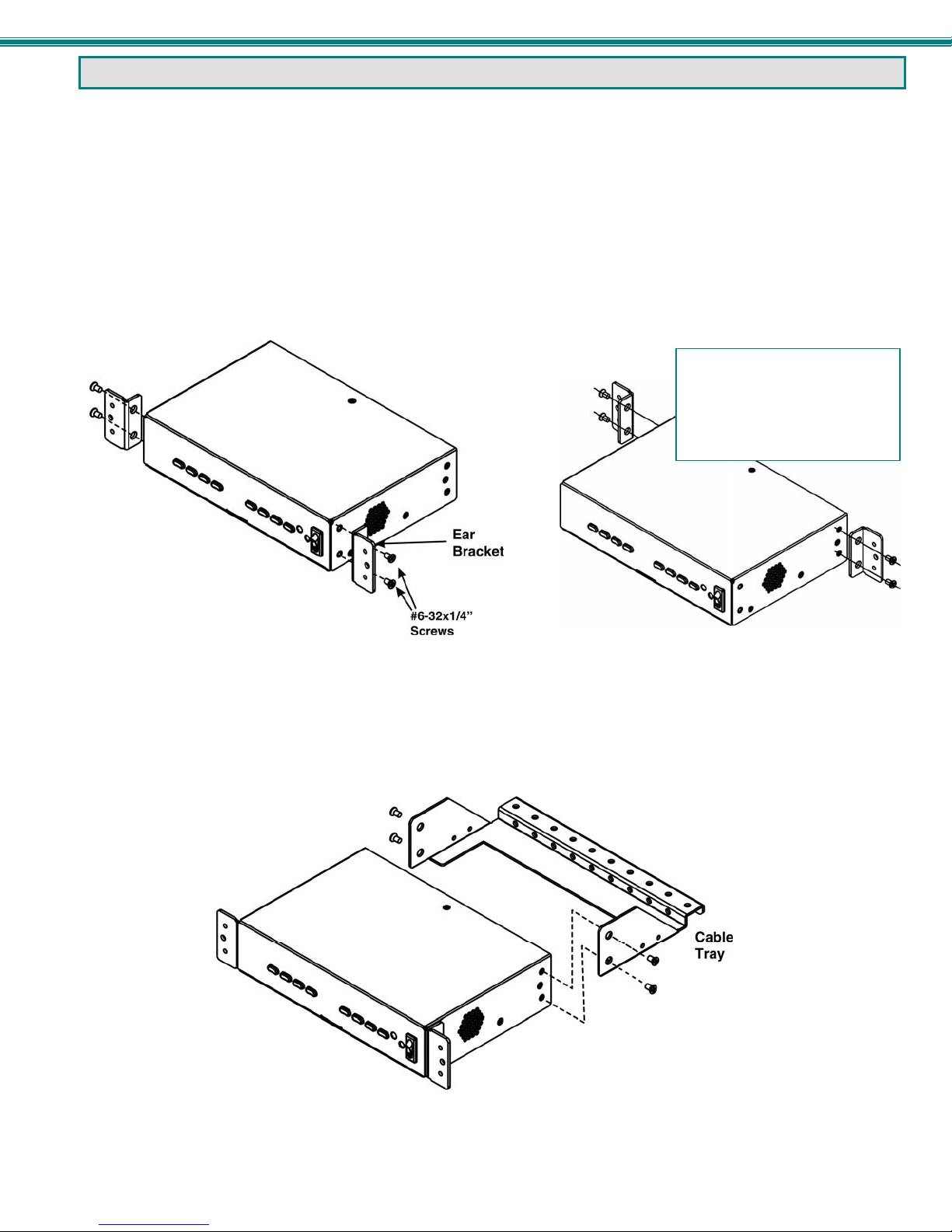
1. Attach the ear brackets to the SPLITMUX. The holes in the brackets should line up with pre-threaded hol es in the sides of the
SPLITMUX. Tighten the screws securely.
Note: If the ear brackets are applied to the rear, the cable management tray cannot be used.
FYI: The same hole pattern is
provided at the front and rear of
the ENVIROMUX, enabling the
ENVIROMUX to be mounted with
the front facing out or rear
facing out.
Figure 1- Attach ear brackets to front corners or rear corners.
2. If the ear brackets have been applied such that the front will face out, assemble the cable tray to the holes in the rear of the
SPLITMUX as shown below.
Figure 2- Attach cable tray (if applicable)
4
SPLITMUX Quad Screen Video Splitter
Single-SPLITMUX mounting
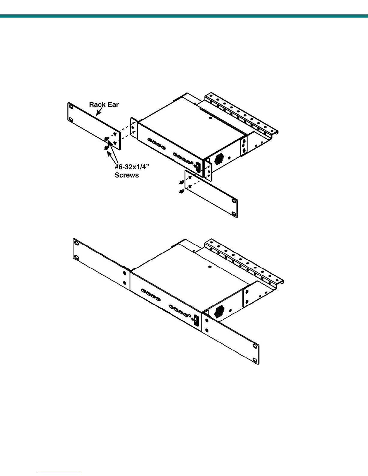
1. To mount a single SPLITMUX in a rack (SPLITMUX-HD-4RT-R), attach the rack mounting ears to the ear brackets using the
#6-32 x 1/4” screws provided. Tighten all screws securely.
Figure 3- Attach rack ears
Figure 4- Assembled unit, ready to mount in rack
2. Install 4 cage nuts (provided) to the rack in locations that line up with the holes in the mounting ears on the SPLITMUX.
3. Secure the SPLITMUX to the rack using the four #10-32x3/4” screws provided. Be sure to tighten all mounting screws
securely.
Note: Do not block power supply vents in the SPLITMUX case. Be sure to enable adequate airflow in front of and
behind the SPLITMUX.
5
SPLITMUX Quad Screen Video Splitter
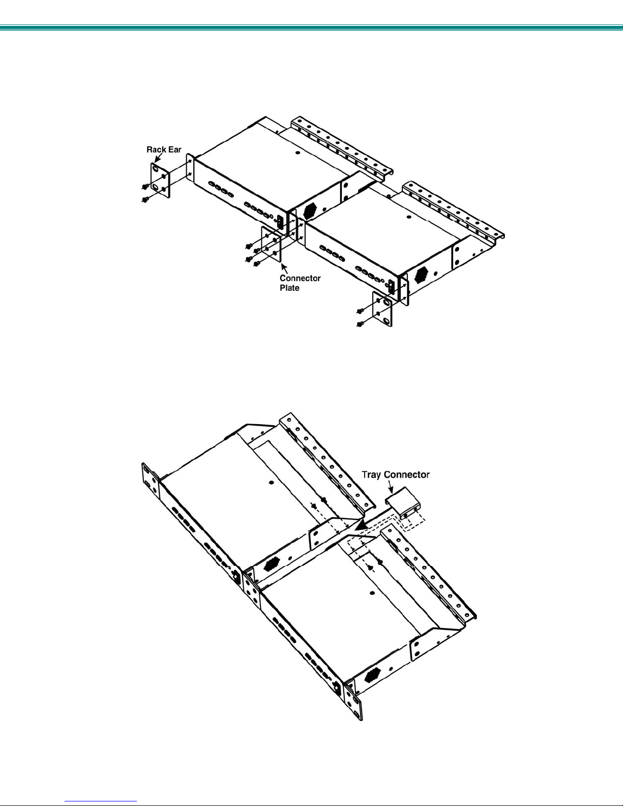
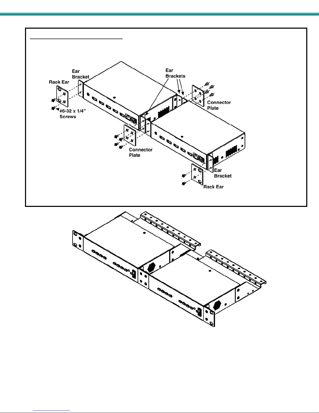
Dual-SPLITMUX mounting
1. To mount a dual SPLITMUX in a rack (SPLITMUX-HD-4RT-2R), attach the rack ears to the far left side of the left SPLITMUX
and right side of the right SPLITMUX using the #6-32 x 1/4” screws provided. Then install a connector plate to join the two
SPLITMUXs in the front.
Figure 5- Attach ears and connector plate
2. Install a cable tray connector between the cable trays using 4 more #6-32x1/4” screws.
Figure 6- Attach cable tray connector
6
SPLITMUX Quad Screen Video Splitter
Reversible Mounting Assembly
If the SPLITMUXs will have the cable connections facing the front of the rack, then two more ear brackets will need to be installed
to the rear corners of the cases that will be closest to each other. (Install these before attaching the connector plate to the front. )
Once the ear brackets are applied, the ears and connector plates can be attached.
Figure 7- Assembly method for SPLITMUX with cables facing forward
Figure 8- Assembled SPLITMUX-HD-4RT-2R
3. Tighten all screws securely. The SPLITMUX-HD-4RT-2R is ready for mounting.
4. Install 4 cage nuts (provided) to the rack in locations that line up with the holes in the mounting ears on the SPLITMUX
assembly.
5. Secure the SPLITMUX to the rack using the four #10-32x3/4” screws provided. Be sure to tighten all mounting scre ws
securely.
Note: Do not block vents in the SPLITMUX case. Be sure to enable adequate airflow in front of and behind the
SPLITMUX.
7
SPLITMUX Quad Screen Video Splitter
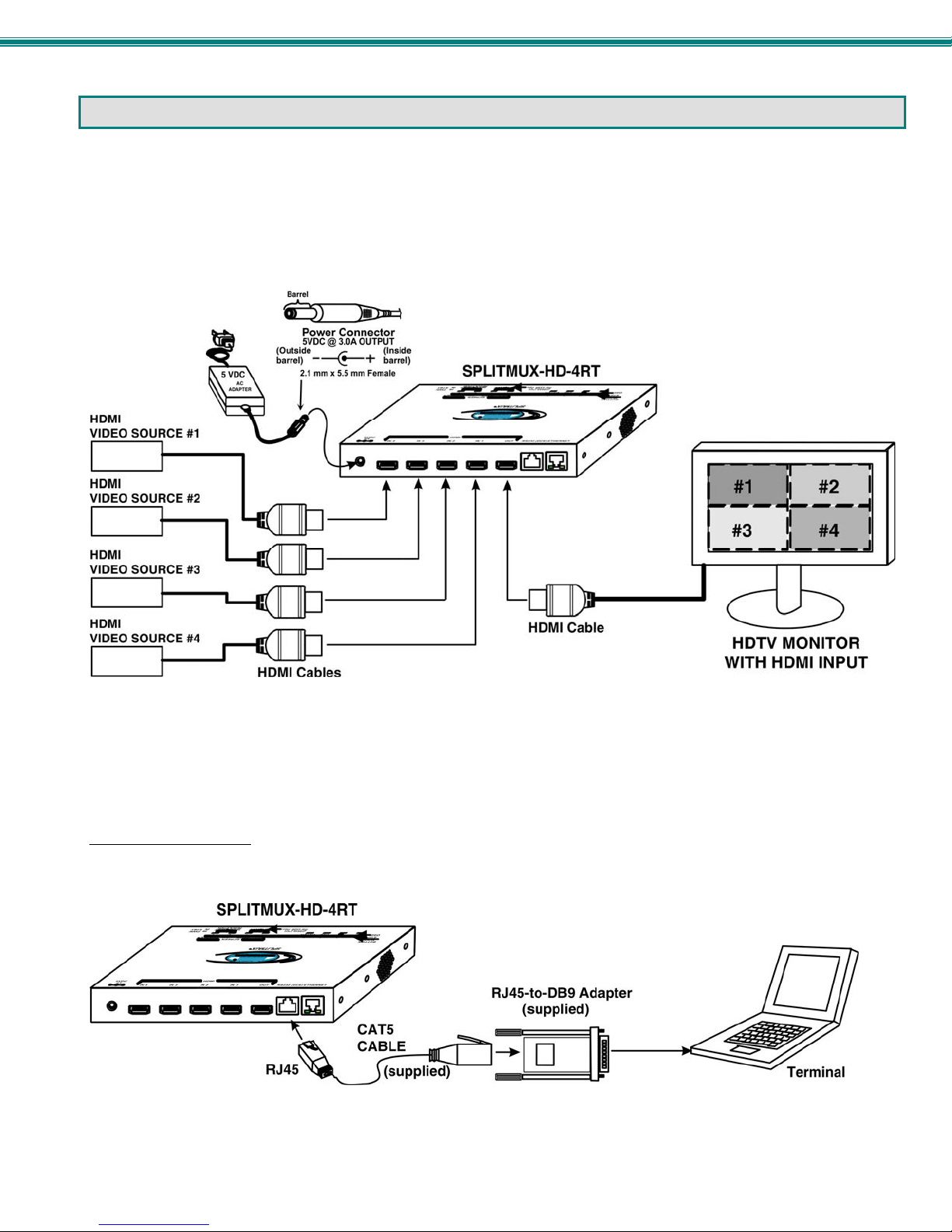
INSTALLATION
1. Connect each of the HDMI or DVI video sources to the ports on the SPLITMUX marked “HDMI Inx” (x = 1-4).
2. Connect the display to the port marked “HDMI OUT”.
3. Connect the power supply to the power jack and plug it in. In approximately 20 seconds, the LED on the SPLITMUX will
illuminate red (standby).
4. Press the switch on the front to power the SPLITMUX ON. Within 20 more seconds the LED will change from red to green
(ON) and the SPLITMUX will be ready to use.
Figure 9- Video Source/Display Connections
Terminal Connection for RS232
If control via serial connection is going to be used, serial control can be achieved by connecting a control terminal to the “RS232”
port .
To use the “RS232” port
SPLITMUX. Plug the other end of the CAT5 cable into an RJ45-to-DB9F adapter (supplied), and connect the adapter to the
RS232 port on the control terminal.
Figure 10- RS232 Terminal Connection
, connect one end of a CAT5 patch cable (supplied) to the port labeled “RS232” on the rear of the
8
SPLITMUX Quad Screen Video Splitter
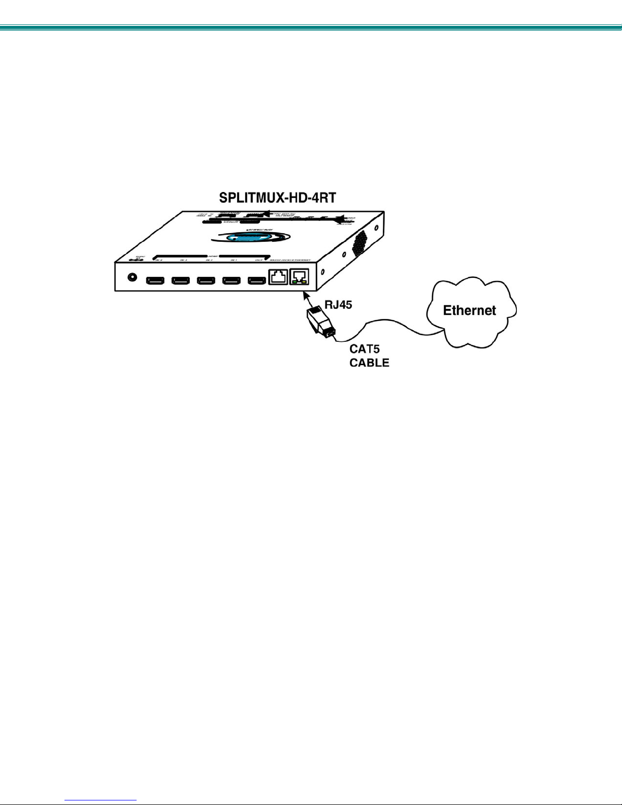
Ethernet Connection for Remote User Control
To make a remote connection, over the Ethernet, from anywhere on the local area network, connect a CAT5/5e/6 Ethernet
cable with RJ45 male connectors on the ends, wired straight through (pin 1 to pin 1, pin 2 to pin 2, etc.). Up to 8 users can
connect to the SPLITMUX using the Ethernet at a time.
Note: A direct connection from a computer’s Ethernet port to the SPLITMUX “ETHERNET” port may also be made using
the same cable.
Figure 11- Ethernet connection
9

SPLITMUX Quad Screen Video Splitter
POWER ON
When you plug in the AC adapter between the SPLITMUX and your power supply, with the power switch OFF, the LED on the
SPLITMUX will illuminate red after approximately 20 seconds. To use the SPLITMUX, press the power switch to ON. After 20
more seconds the LED will change from red (standby) to green (ON). The SPLITMUX is now powered up and ready to use.
CONTROL METHODS
The SPLITMUX can be controlled using any of six methods;
Standard Mode using the front panel buttons
OSD Mode using the front panel buttons,
Using the Command Line Interface either through RS232 or remote connection
Using a Text Menu either through RS232 or remote connection
Using a hand-held IR Remote Control
Remotely through the Web Interface using an Ethernet connection.
Front Panel Buttons
The buttons on the front panel have two separate sets of functions, depending upon what mode the SPLITMUX is in; Standard
Mode or OSD Mode.
Standard Mode
In Standard Mode, the left 4 buttons control which video source is viewed as the active image on the monitor, whether the
SPLITMUX is in Full or PiP mode. The right 4 buttons determine which mode format the monitor will display the video signals in.
¾ When FULL is pressed, the input selected using b uttons 1 throu gh 4 (or “active” image) will be the only image on
the display.
¾ When QUAD is pressed, images from all 4 inputs will be displayed equally on the monitor.
¾ When PIP is pressed, the active image will occupy the entire screen and t he images from the remaining inputs will
be displayed in lower resolution on the right side of the screen.
¾ When CUSTOM is pressed, the images will be displayed in whatever way you have the SPLITMUX configured to
present them. Each input can be sized and positioned on the screen as desired.
In FULL screen mode, only the active video source will be displayed. The image will be viewed at full size
and maximum resolution.
10
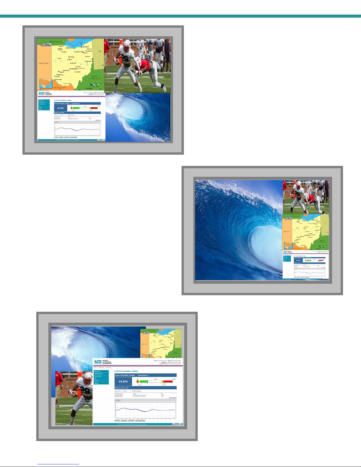
SPLITMUX Quad Screen Video Splitter
In PIP mode (right) , either 2, 3 or all 4 video sources can be
displayed, with the active source being displayed in its
entirety on the full screen and the remaining selected
images at a reduced resolution for simultaneous viewing.
The position of the reduced images can be configured for
preferred viewing.
In CUSTOM mode (below) the 4 video sources can be
placed where ever you want, at what ever size you want.
The amount of each source that is viewed is determined by
your configuration.
In QUAD screen mode, all four video sources share the screen
equally. Each video source is displayed completely.
11
SPLITMUX Quad Screen Video Splitter
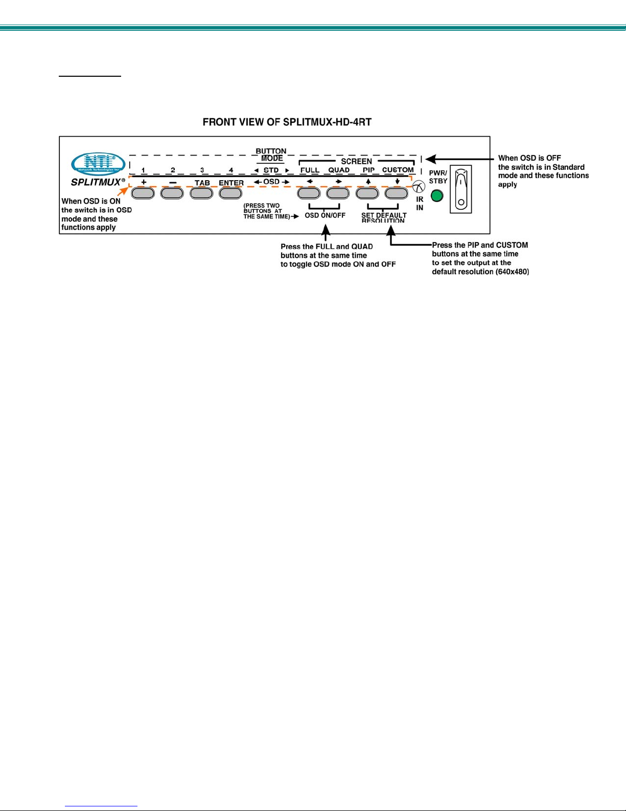
OSD Mode
In OSD Mode, the buttons are used to navigate and control the SPLITMUX using the OSD menu. To bring up the OSD menu,
press the FULL and QUAD buttons at the same time. To exit the OSD menu, press them again.
Figure 12- Front Panel Button Functions
Reset Resolution
In the event an incompatible resolution setting is applied to the SPLITMUX, to quickly restore the images of video sources to the
SPLITMUX, press the PIP and CUSTOM buttons at the same time. This will reset the output to the default resolution of
640x480 @60Hz.
12
SPLITMUX Quad Screen Video Splitter
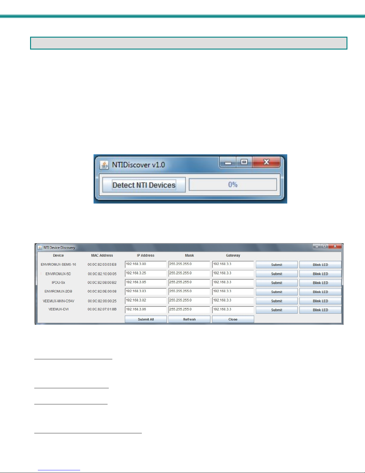
DEVICE DISCOVERY TOOL
In order to easily locate NTI Devices on a network, the NTI Device Discovery Tool may be used. A link to the Discovery Tool is
provided on the web page that appears when you insert the instruction manual CD provided into your CD ROM drive. Either click
on the link or browse the CD to locate the NTIDiscover.jar file. The Discover Tool can be run from the CD or it can be saved
to a location on your PC. Either way, to open it just double-click on the file NTIDiscover.jar . This will open the NTI Device
Discovery Tool.
Note: The Device Discovery Tool requires the Java Runtime Environment (version 6 or later) to operate. A copy of Java
version 6 is provided on the CD and a link to the web page from which it can be downloaded and installed is also on the
CD.
Note: The computer using the Device Discovery Tool and the NTI Device must be connected to the same subnet in order
for the Device Discovery Tool to work. If no devices are found, the message “No Devices Found” will be displayed.
Tip: If your Windows program asks which program to open the NTIDiscover.jar file with, select the Java program.
Figure 13- Device Discovery Tool
Click on the “Detect NTI Devices” button to start the discovery process. After a short time, the tool will display all NTI devices on
your network, along with their network settings.
How to Use the Device Discovery Tool
To Change a Device’s Settings
on the Enter key, or the Submit button on that row. If the tool discovers more than one device, the settings for all devices can be
changed and you can click on the Submit All button to submit all changes at once.
To Refresh the list of devices
To Blink the LEDs of the unit
button will change to a “Blinking….” button. The LEDs of the unit will blink until the Blinking… button is clicked on, or the NTI
Device Discovery Application is closed. The LEDs will automatically cease blinking after 2 hours.
To Stop the LEDs of the unit from blinking
button.
, within the row of the device whose settings you wish to change, type in a new setting and click
, click on the Refresh button.
, click on the Blink LED button (This feature is not supported on all products.) The Blink LED
, click on the Blinking… button. The Blinking…. button will change to a Blink LED
13
SPLITMUX Quad Screen Video Splitter
USE AND OPERATION VIA WEB INTERFACE
A user may configure the settings of the SPLITMUX using the Web Interface via any web browser (see page 2 for supported web
browsers). To access the Web Interface, connect the SPLITMUX to the Ethernet (page 9). Use the Device Discovery Tool (page
13) to setup the network settings. Then, to access the web interface controls, the user must log in.
Note: In order to view all of the graphics in the Web Interface, the browser’s JavaScript and Java must be en abled.
By default, the SPLITMUX is configured to dynamically assign network settings received from a DHCP server on the network it is
connected to. (This can be changed to a static IP address to manually enter these settings in the Network Settings on page 18.)
The SPLITMUX will search for a DHCP server to automatically assign its IP address each time the unit is powered up. If the
SPLITMUX does not find a DHCP server, the address entered into the static IP address field (page 18-default address shown
below) will be used. If a DHCP server on the network has assigned the IP address, use the Device Discovery Tool to identify the
IP address to enter when logging in to the SPLITMUX, or use the OSD menu to view the System Info page.
Note: The computer using the Device Discovery Tool and the NTI Device must be connected to the same subnet in order
for the Device Discovery Tool to work. If no devices are found, the message “No Devices Found” will be displayed.
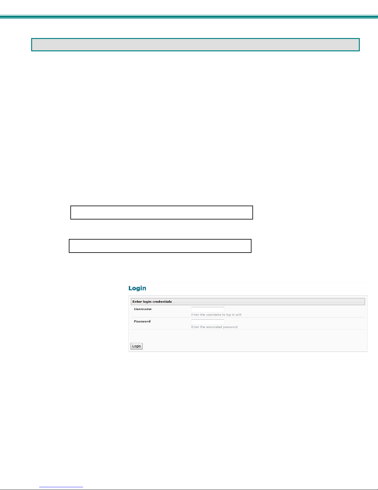
Log In and Enter Password
To access the web interface, type the current IP address into the address bar of the web browser. (The default IP address for the
SPLITMUX is shown below):
To open a SSL-encrypted connection, type:
Address
A log in prompt requiring a username and password will appear:
Username = root
http://192.168.1.30
https://192.168.1.30
Password = nti
(lower case letters only)
Note: usernames and passwords
are case sensitive
Figure 14- Login prompt to access web interface
14
SPLITMUX Quad Screen Video Splitter
With a successful log in, a screen similar to the following will appear:
Figure 15- Initial page- Administrator
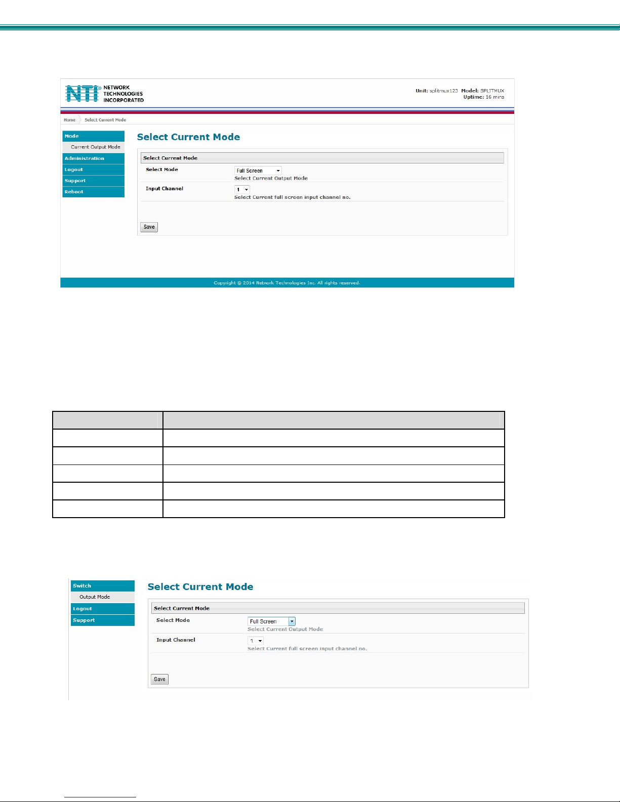
The initial page is the Mode page where the current operating mode of the SPLITMUX is selected and the input channel to be
displayed in Full Screen mode is assigned. A menu to the left is presented to administrative users with access to all pages used
to manage the functions of the SPLITMUX. When the selected mode is Quad, PIP or Custom the Input Channel selected
indicates which input will pass audio through to the output (provided the audio mode for each input is set to Automatic (page 21).
Function Description
MODE Select the current operating mode and main input channel
ADMINISTRATION Configure all network and multi-user access settings (page 17)
LOGOUT Log the user out of the SPLITMUX web interface
SUPPORT Links for downloading a manual or firmware upgrades
REBOOT Enables user to reboot the SPLITMUX using the web interface
A non-administrative user will only have access to select the current mode or to the support links.
Figure 16- Initial page- Non-Admin User
15
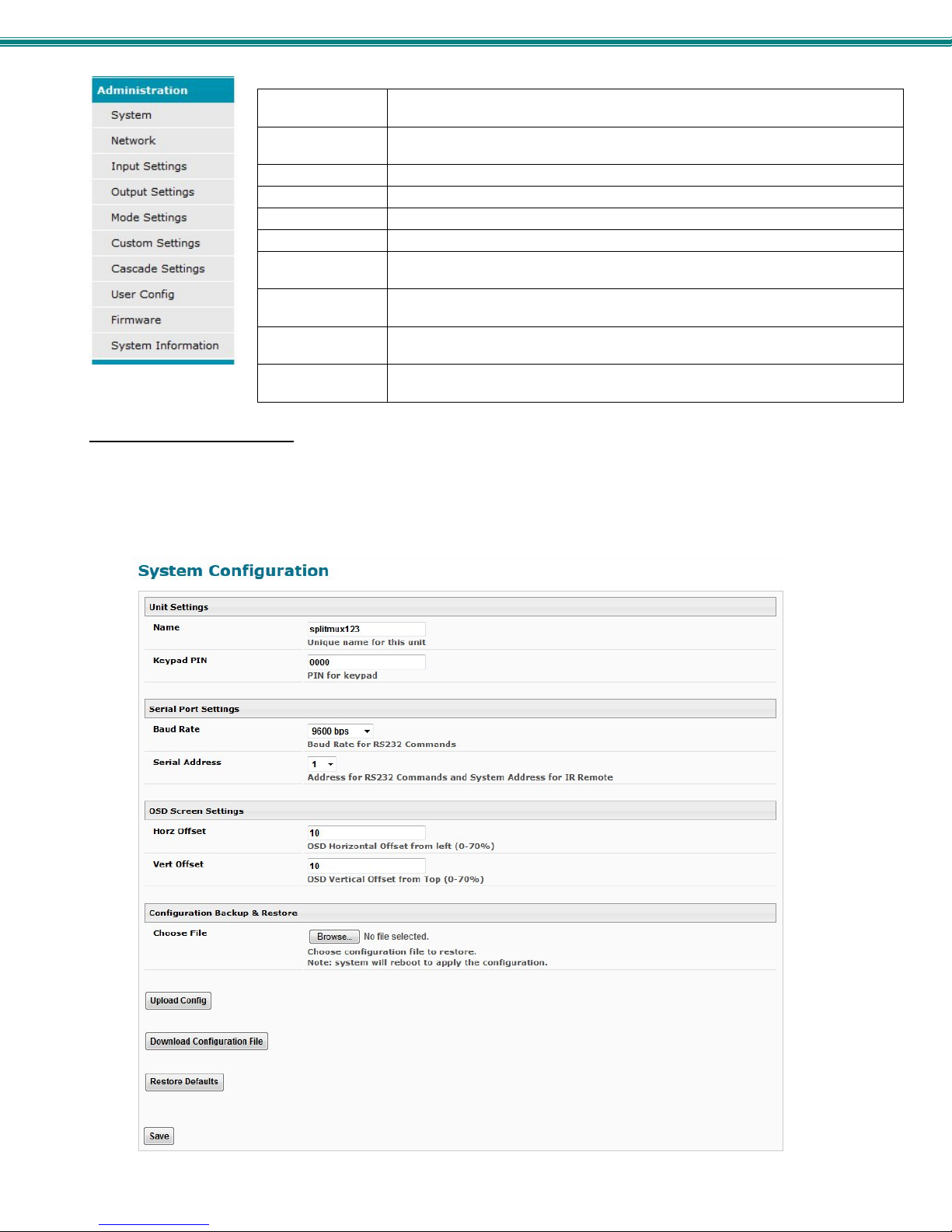
SPLITMUX Quad Screen Video Splitter
System Fields for applying unit settings (name and keypad PIN), Serial configuration
settings, OSD screen position, and configuration backup and restore options
Network Fields for providing all the network settings the SPLITMUX and access control
settings
Input Settings Display configuration settings for each input channel
Output Settings Video and Audio controls for the output channel
Mode Settings All settings for each operating mode of the SPLITMUX
Custom Settings Settings for customizing the layout of the channels on the display
Cascade Settings Settings to control cascading of the video and audio inputs/outputs on other
SPLITMUXs to/from this SPLITMUX
User Config Fields for assigning users, access privileges, passwords, contact settings, and
schedule settings
Firmware For updating the firmware of the SPLITMUX when improved software becomes
available.
System
Information
Provides firmware version, MAC address, network settings and input
connection status
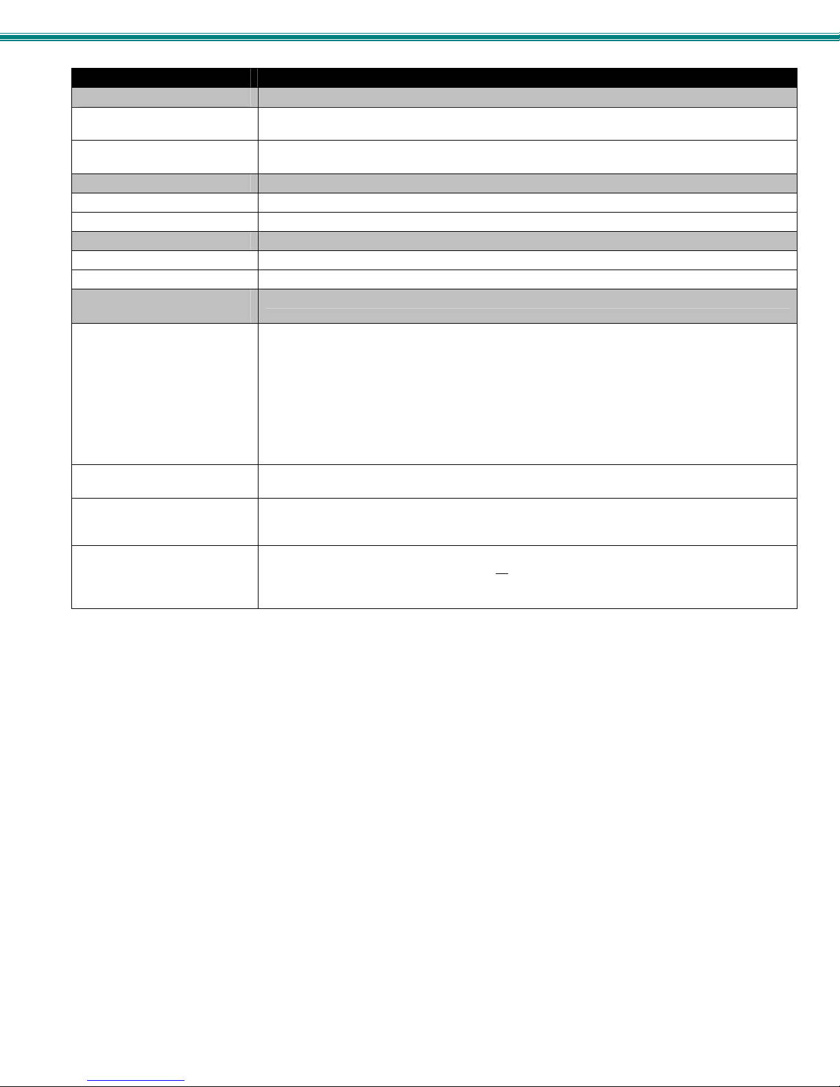
Administration-System
The System Configuration page provides blocks to enter the switch name and a PIN number that will be used to allow access to
the SPLITMUX from the front panel. The name will appear on each page in the web interface identifying which SPLITMUX is
being controlled. Serial port settings for communication with the unit can be entered and the position of the OSD menu on the
monitor is defined. Configuration Backup and Restore provides utility for saving all configuration settings to a file on your PC and
being able to restore them at any time, in addition to being able to restore the SPLITMUX to default settings with the click of a
button.
Figure 17- System Configuration
16
SPLITMUX Quad Screen Video Splitter
System Settings Description
Unit Settings
Name Unique name for this SPLITMUX to appear on the login page and header of each web interface
Keypad Pin PIN number that must be entered before using the keypad to change settings- 4 digits using
Serial Port Settings
Baud Rate Baud rate for RS232 commands- select a value between 1200 and 115200 bps
Serial Address Serial Address for RS232 commands and for the IR Remote- select value from 1-15
OSD Screen Settings
Horiz Offset OSD Horizontal Offset from left (0-70%)
Vert Offset OSD Horizontal Offset from top (0-70%)
Configuration Backup and
Restore
Choose file Browse for a saved configuration file to be restored to the SPLITMUX. Upon selection, press
Upload Config
Download Configuration File Click this button to save the configuration of the SPLITMUX to a location on your PC. This file
Restore Defaults Click this button to restore the SPLITMUX to the configuration settings it had upon receipt from
page
buttons 1-4.
“Save” and the SPLITMUX will restore the configuration settings and reboot. Allow 1 minute
before trying to reconnect and log in again.
Note: The IP address will be set to the IP address in the file and may be different
Note: Before overwriting the existing configuration, consider whether the existing
configuration should be saved first. If it will be saved, be sure to save the current
configuration file under a different name than the configuration file to be loaded.
Click on the Browse button to browse to the file, then click on “Upload Config”, and restore the
SPLITMUX to the configuration stored in the uploaded file.
can be restored using the “Upload Config” button in the event you wish to return the SPLITMUX
to a former state
the factory. Be careful! This will erase all
SPLITMUX will reboot. Allow 1 minute before trying to reconnect and log in again.
Confirmation is required.
user configuration settings. Upon restoration, the
17
 Loading...