

NTI SM-nXm-AV-LCD, VEEMUX A SM-nXm-AV-LCD Installation And Operation Manual

A
NTI
NETWORK
R
TECHNOLOGIES
INCORPORATED
1275 Danner Dr
Aurora, OH 44202
www.networktechinc.com
Tel:330-562-7070
Fax:330-562-1999
®
VEEMUX
Series
SM-nXm-AV-LCD
Audio/Video Matrix Switch
Installation and Operation Manual
MAN069 Rev Date 2/5/2014

TRADEMARK
VEEMUX is a registered trademark of Network Technologies Inc in the U.S. and other countries.
COPYRIGHT
Copyright © 2002, 2014 by Network Technologies Inc. All rights reserved. No part of this publication may be reproduced, stored
in a retrieval system, or transmitted, in any form or by any means, electronic, mechanical, photocopying, recording, or otherwise,
without the prior written consent of Network Technologies Inc, 1275 Danner Drive, Aurora, Ohio 44202.
CHANGES
The material in this guide is for information only and is subject to change without notice. Network Technologies Inc reserves the
right to make changes in the product design without reservation and without notification to its users.
SOFTWARE VERSIONS
Front Panel LCD Software Version 1.2
Ethernet Control Software Version 1.20
i

TABLE OF CONTENTS
Introduction....................................................................................................................................................................1
Basic Operation ...........................................................................................................................................................1
Supported Web Browsers............................................................................................................................................1
Ordering Information....................................................................................................................................................1
Optional Features .....................................................................................................................................................1
Materials ......................................................................................................................................................................2
Cables..........................................................................................................................................................................2
Default User Name and Passwords ............................................................................................................................2
Features and Functions................................................................................................................................................3
Installation......................................................................................................................................................................4
Connect the Sources...................................................................................................................................................4
Connect the Monitors and Speakers...........................................................................................................................5
Connect RS232 ...........................................................................................................................................................5
Connect to the Ethernet...............................................................................................................................................6
Power Up.....................................................................................................................................................................6
LED Matrix......................................................................................................................................................................6
Control Options.............................................................................................................................................................7
Front Panel LCD with Keypad Control.........................................................................................................................7
Making Connections .................................................................................................................................................7
Volume Control.........................................................................................................................................................8
Memory Functions ....................................................................................................................................................8
Menu Button..............................................................................................................................................................9
Scan Mode................................................................................................................................................................9
RS232 Control..............................................................................................................................................................10
Remote Connection...................................................................................................................................................10
Baud Rate...............................................................................................................................................................10
Unit Address ...........................................................................................................................................................10
Command Protocol....................................................................................................................................................11
Autostatus............................................................................................................................................................12
Matrix Switcher’s Control Program For Windows 9X, NT, 2000, XP, Vista and 7....................................................13
SerTest- RS232 Interface Test Program...................................................................................................................13
Main Options...........................................................................................................................................................13
Matrix Operations....................................................................................................................................................13
Ethernet Operations................................................................................................................................................14
Setup Options.........................................................................................................................................................14
Ethernet Control..........................................................................................................................................................14
Telnet Interface-Port 2000.........................................................................................................................................14
Telnet Interface-Port 2005.........................................................................................................................................16
Command Summary...............................................................................................................................................16
Command Detail.....................................................................................................................................................17
RU-Read Unit Size..............................................................................................................................................17
RO-Read Connection for Output Port .................................................................................................................17
CS- Connect Output Port to Input Port................................................................................................................17
CA- Connect All Output Ports to Input Port.........................................................................................................17
SS_01- Enable Auto Status Mode.......................................................................................................................18
SS_00- Disable Auto Status Mode......................................................................................................................18
SX- Examine connections ...................................................................................................................................18
AO-Read Audio Connection for Output Port .......................................................................................................19
AS-Connect Audio Output Port to Input Port.......................................................................................................19
AA-Connect All Audio Outputs to Input Port........................................................................................................19
AV- Set Audio Volume for Output Port................................................................................................................20
AM- Mute/Unmute Audio Output Port..................................................................................................................20
Terminate telnet session .....................................................................................................................................20
AR- Read Mute and Volume for Audio Output Port ............................................................................................21
Web Interface ............................................................................................................................................................22
Enter the Password ................................................................................................................................................22
Main Menu.................................................................................................................................................................23
ii

Video Switch Page ..............................................................................................................................................23
Audio Switch Page ..............................................................................................................................................25
Setup Pages........................................................................................................................................................26
User Management ..................................................................................................................................................27
Add User..............................................................................................................................................................27
Edit User..............................................................................................................................................................28
Input Names ........................................................................................................................................................29
Output Names......................................................................................................................................................29
Outputs Scanning Sequences.............................................................................................................................30
Update Firmware.................................................................................................................................................32
Change Password Page......................................................................................................................................33
Help Page............................................................................................................................................................33
Update Web Server.............................................................................................................................................33
Logout Page ........................................................................................................................................................34
Device Discovery Tool................................................................................................................................................35
How to Use the Device Discovery Tool.....................................................................................................................35
Infrared Control ...........................................................................................................................................................36
Features And Functions.............................................................................................................................................36
KEYPAD .................................................................................................................................................................36
LCD Display............................................................................................................................................................36
How To Use The IRT.................................................................................................................................................37
Change the Switch..................................................................................................................................................37
Change Output Port................................................................................................................................................38
Change Input Port...................................................................................................................................................38
Set Configuration....................................................................................................................................................39
Battery Replacement.................................................................................................................................................40
Specifications.............................................................................................................................................................40
Troubleshooting.........................................................................................................................................................40
DDC Support................................................................................................................................................................41
RS232 Upgrade OF the Front Panel LCD Firmware.................................................................................................42
RS232 Connection Cables..........................................................................................................................................44
Pinout of RS232 port on VEEMUX-A ........................................................................................................................44
Specifications for Straight-Through Serial Cable for CPU Connection.....................................................................44
Pinout for Matrix-Y-1 Cable .......................................................................................................................................45
Rack Mounting Instructions.......................................................................................................................................45
Specifications..............................................................................................................................................................46
Troubleshooting..........................................................................................................................................................47
Safety Statements .......................................................................................................................................................47
Index.............................................................................................................................................................................47
Warranty Information..................................................................................................................................................48
TABLE OF FIGURES
Figure 1- Install Audio and Video Source Cables ..............................................................................................................................4
Figure 2- Install Monitors and Speakers ............................................................................................................................................5
Figure 3- Connect user terminal for RS232 control............................................................................................................................5
Figure 4- Connect the LAN to the VEEMUX-A...................................................................................................................................6
Figure 5- LED Matrix showing input 5 connected to output 5.............................................................................................................6
Figure 6- RS232 Connections for Daisy-chain.................................................................................................................................10
Figure 7- Web interface Welcome page.........................................................................................................................................22
Figure 8- Web interface Login Prompt.............................................................................................................................................22
Figure 9- Administrator Menu ..........................................................................................................................................................23
Figure 10- Web interface Video Switch page...................................................................................................................................23
Figure 11- Web interface Audio Switch page...................................................................................................................................25
Figure 12- Web interface Setup page..............................................................................................................................................26
Figure 13- Web interface Serial Setup page....................................................................................................................................26
Figure 14- Administration menu.......................................................................................................................................................27
Figure 15- Add User page................................................................................................................................................................27
Figure 16- Edit User settings ...........................................................................................................................................................28
Figure 17- Web interface Video Input Names page.........................................................................................................................29
Figure 18- Output Port Names.........................................................................................................................................................29
Figure 19- Outputs Scanning Sequences page ...............................................................................................................................30
Figure 20- Web interface Update Firmware page............................................................................................................................32
iii

Figure 21- Web interface Password page ........................................................................................................................................33
Figure 22- Updating the Web Server ...............................................................................................................................................33
Figure 23- Web interface Logout page.............................................................................................................................................34
Figure 24- Device Discovery Tool....................................................................................................................................................35
iv

NTI VEEMUX AUDIO/VIDEO MATRIX SWITCH
INTRODUCTION
The SM-nXm-AV-LCD Audio/Video Matrix switch (VEEMUX-A) allows up to 32 audio/video sources (n) to be connected to up to
16 destinations (m). Different destinations can even be connected to the same source. Video resolution up to 1920x12 00@85Hz
is supported with no degradation – guaranteed. Stereo audio is supported, as well as volume control and separate audio/video
switching. An LCD on the front panel indicates the current connections. The VEEMUX-A can be controlled by four methods: Front
Panel LCD with Keypad, RS232 interface, Ethernet, or optional Infrared Remote.
Basic Operation
The VEEMUX-A allows any source to be connected to any destination at any time with no restrictions or limitations.
• Audio and Video connections can be made concurrently or separately (i.e. user 1 can view video from port 3
and hear audio from port 11).
• Video inputs accept any RGBHV, RGBS, or RGsB signal.
• Video outputs are compatible with any RGBHV or RGBS monitor, regardless of input. (RGsB monitor requires
RGsB input)
• Audio inputs accept any standard line level audio (1Vrms or 2.5Vp-p).
• Audio outputs are capable of driving an 8 Ohm speaker load with 200mW of continuous RMS power.
• The Audio output volume of the AV matrix is adjustable for each output port.
• Up to 15 users (including the administrator) can have controlled WEB interface access to the VEEMUX
Supported Web Browsers
Most modern web browsers should be supported. The following browsers have been tested:
• Microsoft Internet Explorer 6.0 or higher
• Netscape 7.0 or higher
• Mozilla FireFox 0.9.2 or higher
Set your browser to always check if there is a newer version of the page than the version stored in cache. This action will ensure
that it will display the most up-to-date information.
Ordering Information
The SM-nXm-AV-LCD Audio/Video Matrix switch (VEEMUX-A) can be ordered in many sizes and with several control options.
The base unit includes a user keypad and an RS232 port to make up a complete system, with an option for an infrared control.
The infrared option is purchased separately, allowing for maximum user satisfaction in each unique configuration.
The VEEMUX-A Audio/Video Matrix switch is built to a specific size ranging from 8 to 32 inputs and 2, 4, 8, 12, or 16 outputs.
Simply order an SM-nXm-AV-LCD where the “n” in the part number represents the number of inputs and the “m” in the part
number represents the number of outputs.
SM-nXm-AV-LCD
Replace the “n” with 8,16, or 32
Replace the “m” with 2,4,8,12, or 16
The following list represents the available sizes that can be ordered:
SM-8x2-AV-LCD SM-16x4-AV-LCD SM-32x2-AV-LCD
SM-8x4-AV-LCD SM-16x8-AV-LCD SM-32x4-AV-LCD
SM-8x8-AV-LCD SM-16x12-AV-LCD SM-32x8-AV-LCD
SM-16x2-AV-LCD SM-16x16-AV-LCD SM-32x16-AV-LCD
Optional Features
• DDC Support (see page 41)- to order, add "D" to the part number (i.e. SM-nXm-AVD-LCD)
• Infrared Control (see page 36)- to order, add "IR" to the part number (i.e. SM-nXm-AV-LCD-IR)
1
NTI VEEMUX AUDIO/VIDEO MATRIX SWITCH
Materials
Materials Supplied with this kit:
• NTI SM-nXm-AV-LCD Audio/Video Matrix switch
• IEC Line cord, country specific
• 4- #10-32 x 3/4" pan head screws and 10-32 cagenuts (server cabinet mounting hardware)
• CD with: a pdf file of this owner's manual
the NTI Discovery Tool
the Matrix Switcher’s Control Program
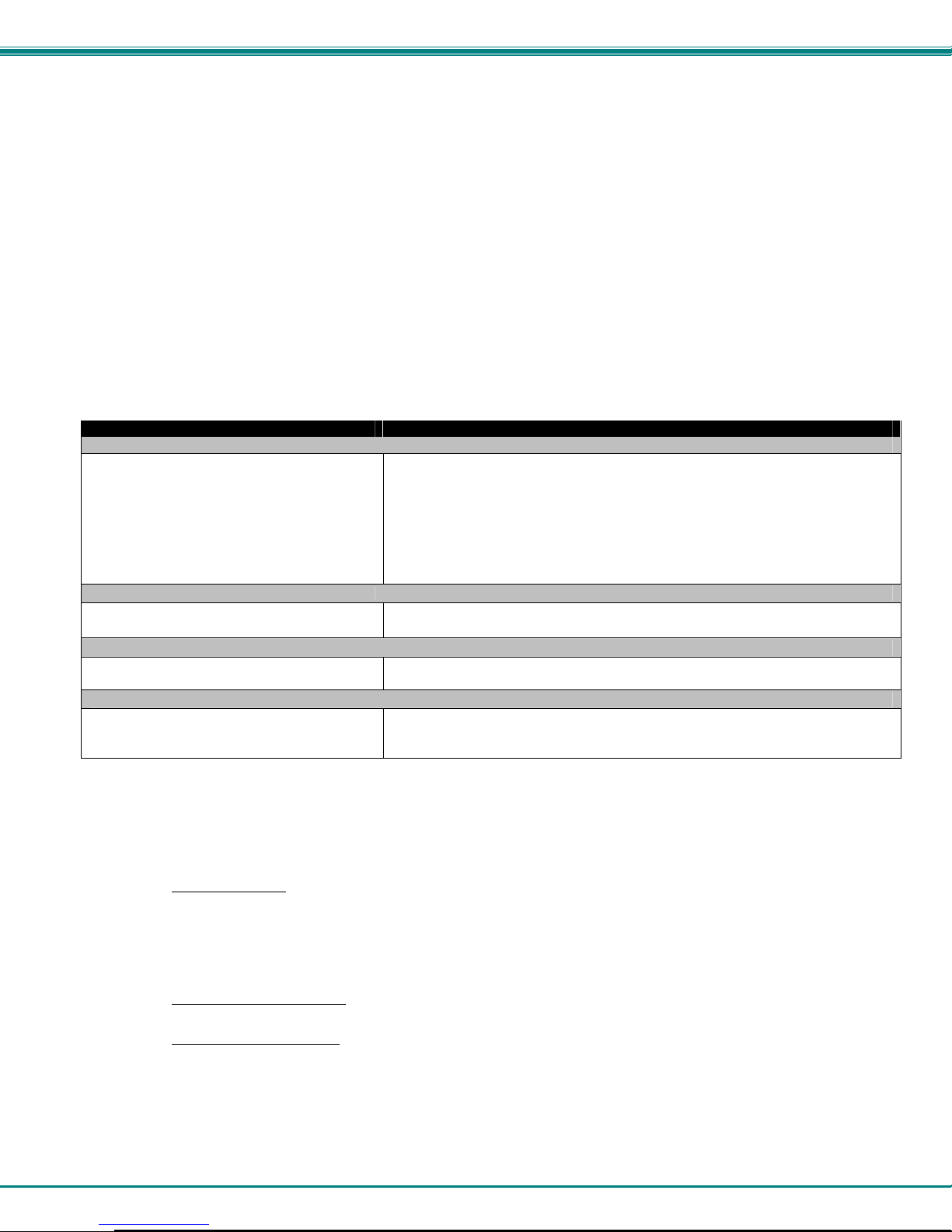
Cables
All cables are sold separately. The following table lists the available stocked cabl es with their length in feet. All of the 15HD and
BNC input and output connectors on VEEMUX-A are female. Custom cables are available – contact NTI for pricing and distance /
resolution limitations.
NTI NAME DESCRIPTION
VGA
VEXT-3/6/10/15/25/35/50/75/100-MM
VEXT-3/6/10/15/25/35/50/75/100
VINT-5B-6
SA-6/10/15/25/35/50-MM
Matrix-Y-1 or see page 44 for alternative
cables
Contact NTI for various lengths and colors Cat5 UTP Cable- Connectors are RJ45 male-Stocked cables are 2 thru 100 feet
Multi-coax high resolution VGA or SVGA video cable. Connectors are 15HD
male-male (used for INPUTS)- 3 thru 100 feet
Multi-coax high resolution VGA or SVGA video cable. Connectors are 15HD
male-female (used for OUTPUTS)- 3 thru 100 feet
Multi-coax high resolution VGA to BNC cable. Connectors are 15HD male to 5
BNC’s- 6 feet long
AUDIO
Audio Interface Cable- Connectors are 3.5mm male-male - 6/10/15/25/35/50
feet long
RS232
RS232 Interface Cable- Connectors are 9D male- female-female 12" long
(also see alternative cable specifications on page 44)
ETHERNET
Custom cables must have RJ45 connectors wired straight thru- pin 1 to pin 1,
etc.
Default User Name and Passwords
The default Telnet password is admin (lower case letters only) . For instruction on using Telnet, see page
14.
(No username is required in order to use Telnet. You will only be prompted for a password.)
The default Web Interface user name
The default Web Interface password
Interface, see page 22.
is Administrator (upper case letter for "A" only).
is admin (lower case letters only). For instruction on using the Web
2
NTI VEEMUX AUDIO/VIDEO MATRIX SWITCH
Front View of VEEMUX-A
ESC
OUT
6 7
MENU
1
123IN4 5
21112
13
5
ETHERNET
NTI
1275 Danner Dr
Aurora, O H 44202
R
S
2
3
2
6
78
NETWORK
TECHNOLOGIES
INCORPORATED
Tel:330-562-7070
Fax:330-562-1999
www.nti1.com
VIDEO 7
VIDEO 8
9
8
VIDEO 5
VIDEO 6
9
0
7
8
*
ENTER
AUDIO OUT (USER)
3
5
4
6
VIDEO 3
VIDEO 4
IN
581234 678
OUT
1
DDC
2
3
4
5
6
7
NTI
Network Technologies Inc
Rear View of VEEMUX-A
1
2
VIDEO 1
VIDEO 2
MONITOR 7
MONITOR 8
MONITOR 5
MONITOR 6
10
R
VEEMUX A
AUDIO IN (CPU)
7
8
MONITOR 3
MONITOR 4
R
34
1
3
5
2
4
6
MONITOR 1
MONITOR 2
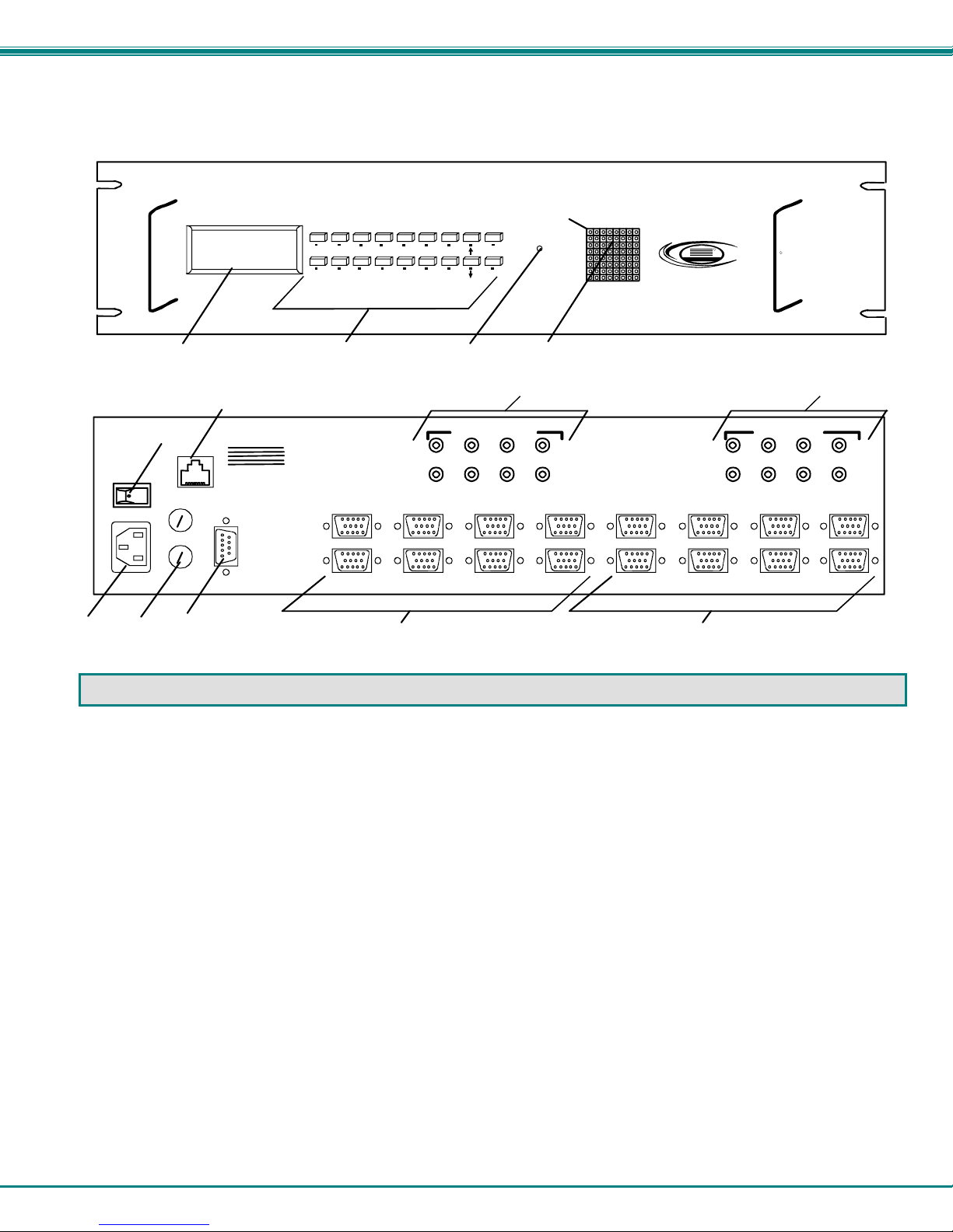
FEATURES AND FUNCTIONS
1. LCD Display- for visual indication of input-to-output connections and for configuration of the VEEMUX.
2. Keypad- buttons for user control over switch functions
3. AUDIO IN- for connection of audio cables from audio sources
4. AUDIO OUT- for connection of audio cables to audio output devices (speakers)
5. Power ON/OFF switch
6. IEC Power Connector- for attachment of power cord (not available on all units)
7. Fuse Holder- holder for replaceable overcurrent 2A 240VAC Fast-blo protection fuse
8. RS232 In/Out - 9D female connector- for attaching RS232 interface cable from a user terminal
9. VIDEO x- 15HD female connectors- for attachment of video cables from video sources
10. MONITOR x- 15HD female connectors- for connection of video output devices
11. DDC button- for manual update of DDC information between the monitor and the source(s) attached (optional)
12. LED Matrix- for visual indication of all input-to-output connections (page 6) (not available on all models)
13. ETHERNET- RJ45 female connector- for connection of CAT5 cable to Local Area Network (LAN) for WEB interface
3
NTI VEEMUX AUDIO/VIDEO MATRIX SWITCH
INSTALLATION
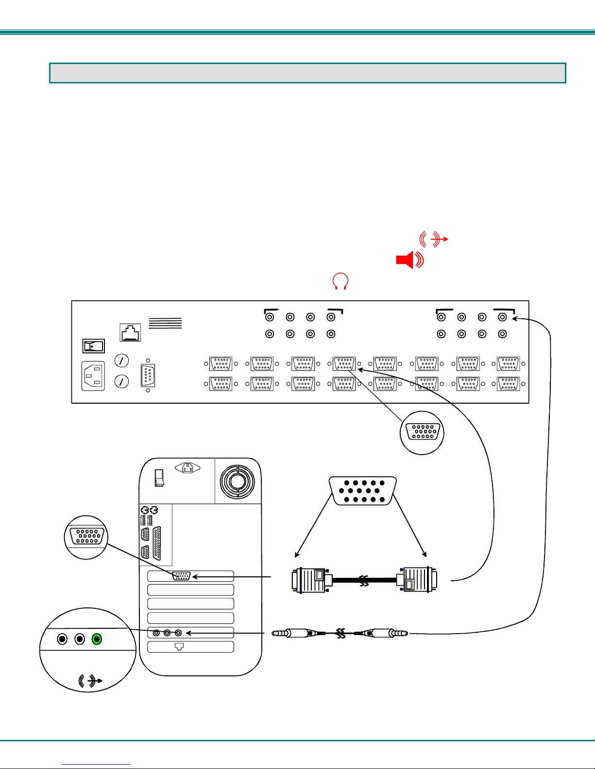
Connect the Sources
1. Turn OFF power to all video sources (inputs) that will be connected to the VEEMUX-A before connecting or
disconnecting any cables.
2. For each video source, connect a VEXT-xx-MM cable from the video port of the source to a video input
("VIDEO 1") of the VEEMUX-A (see Fig. 1).
3. For each audio source, connect a SA-xx-MM cable from the audio source to an audio input ( "AUDIO IN ") port.
Notes:
The audio port on a CPU may be marked "line out", "spkr", or "headphones". If all 3 jacks are available, use
the jack marked "line out".
The "line out" jack is typically lime green and may be marked with this symbol
The "spkr" jack is typically orange, and may be marked with this symbol
The "headphones" jack may be marked with this symbol
ETHERNET
Video Port
15HD Female
Video Connector
Audio Port
ONE WILL BE MARKED "li ne
out" ,"spkr", "headphones"
OR WITH THIS SYMBOL
line
out
Figure 1- Install Audio and Video Source Cables
NETWORK
NTI
1275 Danner Dr
Aurora, OH 44202
R
S
2
3
2
TECHNOLOGIES
INCORPORATED
Tel:330-562-7070
Fax:330-562-1999
www.nti1.com
Rear View of a CPU
VIDEO 7
VIDEO 8
VIDEO 5
VIDEO 6
AUDIO OUT (USER)
5
7
6
8
VIDEO 3
VIDEO 4
1
3
2
4
VIDEO 1
VIDEO 2
Rear View of VEEMUX-A
15HD Male
Video Connector
HD15-Male
3.5mm Stere o
Plug
SA-xx-MM
4
VEXT-xx-MM
MONITO R 7
MONITO R 8
15HD Female
Video Connector
HD15-Male
3.5mm Stereo
Plug
MONITO R 5
MONITO R 6
AUDIO IN (CPU)
7
8
MONITO R 3
MONITO R 4
1
3
5
2
4
6
MONITOR 1
MONITOR 2
NTI VEEMUX AUDIO/VIDEO MATRIX SWITCH
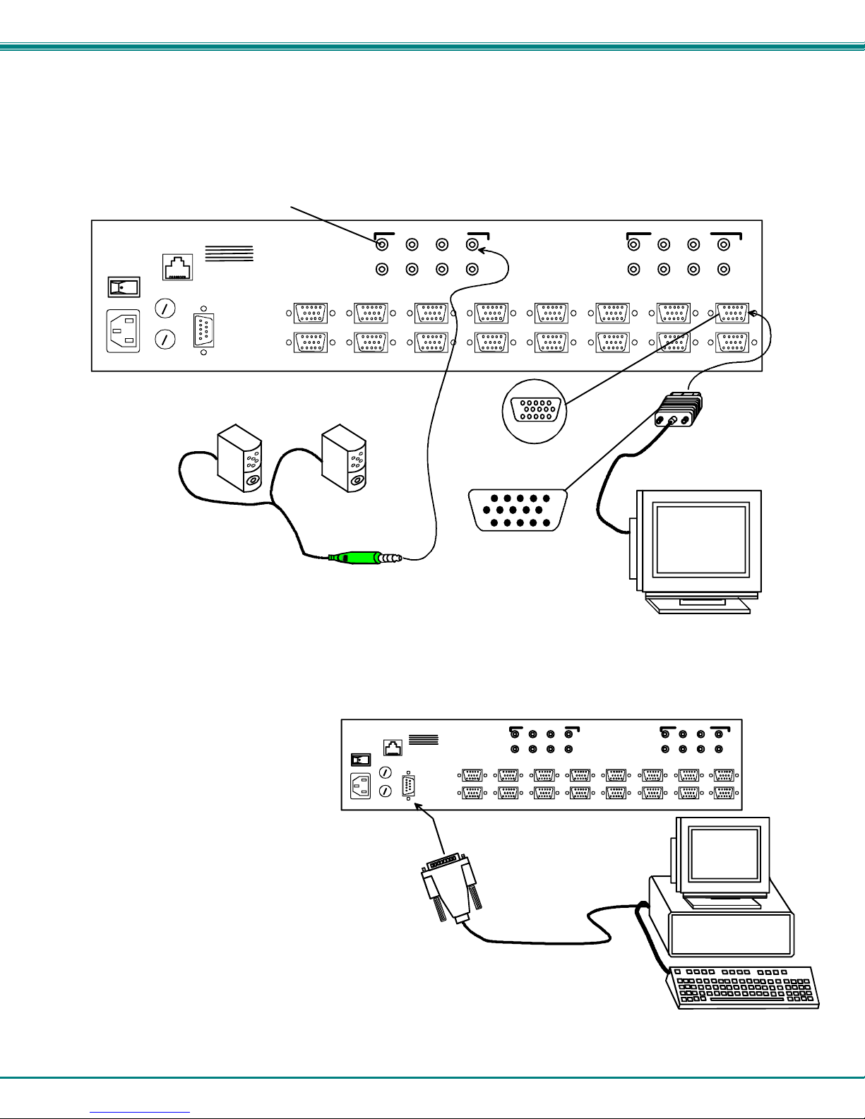
Connect the Monitors and Speakers
1. Connect a video output device to the port labeled MONITOR 1 on the rear of the VEEMUX-A (see Fig. 2).
2. Repeat step 6 for remaining output devices (monitors).
3. Connect audio output device (speakers) to port labeled AUDIO OUT 1.
4. Repeat step 8 for remaining audio output devices, connecting them to any remaining AUDIO OUT ports.
ETHERNET
Figure 2- Install Monitors and Speakers
3.5mm Ste reo
Jack
NTI
1275 Danner Dr
Aurora, OH 44202
www.nti1.com
R
S
2
3
2
NETWORK
TECHNOLOGIES
INCORPORATED
Tel:330-562-7070
Fax:330-562-1999
VIDEO 7
VIDEO 8
Speakers
Rear View of VEEMUX-A
VIDEO 5
VIDEO 6
3.5mm Ste reo
Plug
AUDIO OUT (USER)
7
8
5
6
VIDEO 3
VIDEO 4
3
4
1
2
VIDEO 1
VIDEO 2
MONITOR 7
MONITOR 8
15HD Female
Video Connector
15HD Male
Video Connector
MONITOR 5
MONITOR 6
AUDIO IN (CPU)
7
8
MONITOR 3
MONITOR 4
5
6
VGA
Multi-Scan
Monitor
3
4
MONITOR 1
MONITOR 2
1
2
Connect RS232
RS232 control can be achieved using a
separate user terminal or CPU with a
terminal program.
To make a terminal connection, connect a
serial cable (specifications on page 44)
between the user terminal and the 9 pin
DIN female connector on the VEEMUX-A
labeled "RS232". (See Fig. 3)
Figure 3- Connect user terminal for RS232 control.
ETHERNET
NTI
1275 Danner Dr
Aurora, OH 44202
www.nti1.com
R
S
2
3
2
Rear View of VEEMUX-A
NETWORK
TECHNOLOGIES
INCORPORATED
Tel:330-562-7070
Fax:330-562-1999
VIDEO 7
VIDEO 8
VIDEO 5
VIDEO 6
9D-male
RS232 connector
5
AUDIO O UT (USE R)
8
1234567
VIDEO 1
VIDEO 3
VIDEO 2
VIDEO 4
User Terminal
MONITOR 7
MONITOR 8
MONITOR 5
MONITOR 6
AUDIO I N (CPU)
8
MONITOR 3
MONITOR 4
1234567
MONITOR 1
MONITOR 2
VGA
Multi-Scan
Monitor
NTI VEEMUX AUDIO/VIDEO MATRIX SWITCH
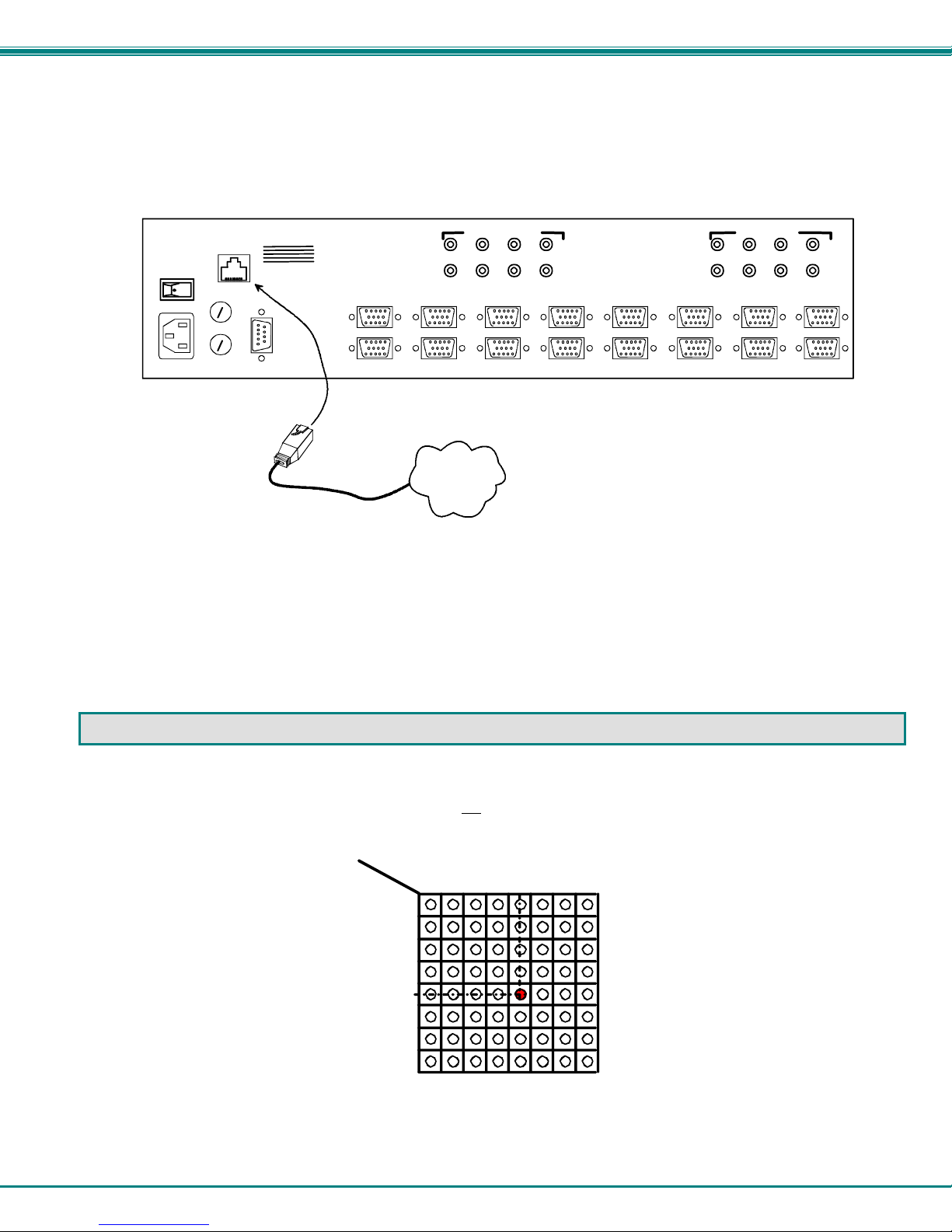
Connect to the Ethernet
If the Telnet Interface (page 14) or Web Interface (page 22) will be used, an Ethernet connection to the Local Area Network (LAN)
must be made using Cat5 cable with RJ45 connectors attached. Wiring between connectors should be straight throu gh (pin 1 to
pin 1, pin 2 to pin 2, etc..) Connect a Cat5 cable between the connector labeled "ETHERNET" and the LAN (see Fig. 4).
ETHERNET
NTI
1275 Danner Dr
Aurora, OH 44202
www.nti1.com
NETWORK
TECHNOLOGIES
INCORPORATED
Tel:330-562-7070
Fax:330-562-1999
R
S
2
3
2
RJ45 male
connector
Rear View of VEEMUX-A
AUDIO OUT (USER)
5
7
6
8
VIDEO 7
VIDEO 8
VIDEO 5
VIDEO 6
VIDEO 3
VIDEO 4
LAN
AUDIO IN (CPU)
5
1
3
2
4
VIDEO 1
VIDEO 2
MONITOR 7
MONITOR 8
MONITOR 5
MONITOR 6
7
8
MONITOR 3
MONITOR 4
6
3
4
MONITOR 1
MONITOR 2
1
2
Figure 4- Connect the LAN to the VEEMUX-A
Power Up
1. Plug the VEEMUX-A to an AC power outlet.
2. Turn ON power to the VEEMUX-A.
3. Turn ON power to any or all of the video and/or audio sources connected to the VEEMUX-A.
LED MATRIX
(not available on all models)
The LED Matrix is a grid of LEDs on the front panel of the VEEMUX-A. This grid is used to provide a visual indication of all
connections between video sources and destinations. It is not
(video source) is connected to an output (video destination), follow the LEDs down and to the right (respectively) until they
intersect. The illuminated LED at the point of intersection indicates the input is connected to the output by the VEEMUX-A.
OUT
IN
1234 678
1
2
3
4
5
6
7
8
an indication of audio connections. To determine if an input
5
Figure 5- LED Matrix showing input 5 connected to output 5
6
NTI VEEMUX AUDIO/VIDEO MATRIX SWITCH
CONTROL OPTIONS
The VEEMUX-A Audio/Video Matrix Switch has four methods of control:
• Front Panel LCD with Keypad
• Directly via an RS232 interface
• Remotely via Ethernet
• Infrared Remote (optional)
Every unit comes standard with the Front Panel LCD with Keypad, RS232, and Ethernet connection built-in. If desired, the
Infrared Remote option may be requested at the time of the order. The Infrared Remote option requires the purchase of a
separate remote control device (Infrared transmitter) as well as an Infrared receiver to be installed in the VEEMUX-A. No software
is involved (see page 36 – Infrared Control). With the RS232 or WEB Interface options, there are no external d evices to be
purchased. NTI provides software commands as well as a test program to ensure the RS232 functions properly (see page 10 –
RS232 Control) and a graphic user interface for use with a RS232 or Ethernet connection.
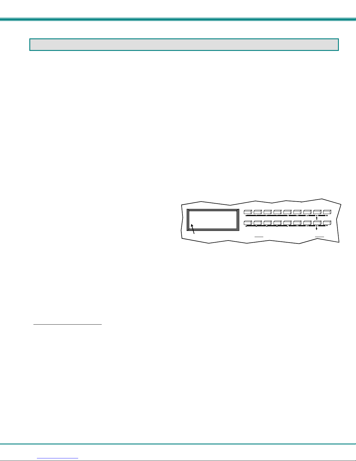
Front Panel LCD with Keypad Control
The front panel keypad and LCD (drawing below) allow the user to view and change current aud io and video connections, adjust
audio volume and configure the RS-232 control interface. The keypad buttons perform the following functions.
ESC Escape back to the main display.
0 – 9 Used to enter numbers. ( # )
OUT Specifies output port
IN Specifies input port
ENTER Forces selection of single digit entries
Display next 4 connections
Display previous 4 connections
MENU Display the RS-232 menu. (See RS232 control on page 10.)
* Additional functions
OUT: 1 2 3 4
V
IN: 1 2 3 4
LCD WILL CYCLE TO DISPLAY A "v" FOR ALL VIDE O INPUTS FIRS T, THE N A "a" FOR ALL AUDI O INP UTS.
ESC
MENU
OUT
6
7890
1
IN
2 3
5
4
*
ENTER
Making Connections
The VEEMUX-A allows audio and video connections to be made concurrently or separ ately. In both situations, the output port
number must always be entered first.
• Connecting audio and video concurrently
When making this connection, any one of the following commands may be used:
1. <OUT>, Single digit output port number, <IN> or <ENTER>, Single digit input port number, <ENTER>.
Ex: <OUT> 3 <IN> 5 <ENTER>
2. Single digit output port number, <ENTER>, Single digit input port number, < ENTER>.
Ex: 3 <ENTER> 5 <ENTER>
3. Double digit output port number, Double digit input port number.
Ex: 03 05
All outputs can be connected to a single input by using <*>:
1. <*>, Single digit input port number, <ENTER>
Ex: <*> 5 <ENTER>
2. <*>, Double digit input port number
Ex: <*> 05
7

NTI VEEMUX AUDIO/VIDEO MATRIX SWITCH
• Connecting audio only
To make an audio connection without changing the current video connection, use any of the follo wing commands:
1. <OUT>, <
Ex: <OUT> <
2. <OUT>, <▼>, <▼>, Double digit output port number, Double digit input port number.
Ex: <OUT> <
All audio outputs can be connected to one audio input by using <*>:
1. <*>, <
Ex: <*> <▼> <▼> 5 <ENTER>
2. <*>, <
Ex: <*> <▼> <▼> 05
• Connecting video only
To make a video connection without changing the current audio connection, use any of the following commands:
1. <OUT>, <
Ex: <OUT> <▲> 3 <IN> 5 <ENTER>
2. <OUT>, <
Ex: <OUT> <
All video outputs can be connected to one video input by using <*>:
1. <*>, <
Ex: <*> <
2. <*>, <▲>, Double digit input port number
Ex: <*> <
▼>, <▼>, Single digit output port number, <IN> or <ENTER>, Single digit input port number, <ENTER>.
▼> <▼> 3 <IN> 5 <ENTER>
▼> <▼> 03 05
▼>, <▼>, Single digit input port number, <ENTER>
▼>, <▼>, Double digit input port number
▲>, Single digit output port number, <IN> or <ENTER>, Single digit input port number, <ENTER>.
▲>, Double digit output port number, Double digit input port number.
▲> 03 05
▲>, Single digit input port number, <ENTER>
▲> 5 <ENTER>
▲> 05
Volume Control
The volume level can be adjusted on each output port.
• To increment <▲> or decrement <▼> the volume, use the following command:
<OUT>, <▼>, Double digit output port number, <▲> increment or <▼> decrement, <ENTER>
Ex 1: <OUT> <
▼> 03 <▲> <▲> <▲> <ENTER>
This will increment the volume by +6dB (2dB/ press).
Ex 2: <OUT> <
▼> 14 <▼> <▼> <ENTER>
This will decrement the volume by -4dB.
• To Mute, use the command:
<OUT>, <▼>, Double digit output port number, the <0> key, <ENTER>
Ex: <OUT> <
▼> 03 0 <ENTER>
This will mute output 3
• To Un-mute, use the instruction:
<OUT>, <▼>, Double digit output port number, the <1> key, <ENTER>
Ex: <OUT> <
▼> 03 1 <ENTER>
This will un-mute output 3
Memory Functions
There are 100 memory locations(0-99) available to save connection configurations. Location 0 is the power-ON default).
• Saving Connections
To save all current connections, use the following command:
<*>, <OUT>, Memory location, <ENTER>
Ex: <*> <OUT> 5 <ENTER>
• Restoring Connections
To restore connections from memory, use the following command:
<*>, <IN>, Memory location, <ENTER>
Ex: <*> <IN> 5 <ENTER>
Note: If the current switch configuration includes assigned Scan Mode dwell time values (page 9), to save the current
configuration be sure to assign a memory location to it. Otherwise, when the VEEMUX-A is powered OFF, all dwell
time values will be erased. Also, saving the configuration as memory location 0 will cause it to be the power-ON default
configuration.
Configurations that are saved into memory locations via
the keypad can be recalled via the web interface (page 20)
and vice versa.
8
NTI VEEMUX AUDIO/VIDEO MATRIX SWITCH
I
Menu Button
The Menu button is used to configure the RS-232 port.
• The baud rate is selected from the “Baud Rate Menu.” To access this menu, use the command:
<MENU>, the <1> key
Next, press the keypad number corresponding with the desired baud rate:
<1> – 9600
<2> – 4800
<3> – 2400
<4> – 1200
Ex: <MENU> 1 1
This will select 9600 baud
• To set the switch address, use the following instruction:
<MENU>, the <2> key, Double digit address (from 01 to 15- the default address is 01)
Ex: <MENU> 2 03
This will set the address at 03
Scan Mode
Scan Mode causes output ports (audio and video) to automatically switch from one audio and video input port to the next
consecutive audio and video input port after a specified period of time (referred to as the dwell time). Audio and video port
switching will continue indefinitely and no ports will be skipped, wheth er there are audio or video sources connected to them or
not. If desired, the VEEMUX can be configured to skip the scanning of specific ports using the RS232 Command Protocol (page
11) or Telnet (page 14) .
Dwell time settings can be any value from 0 seconds (000) to 255 seconds. A setting of 000 seconds (the default setting)
disables Scan Mode for that output port. If Scan Mode is disabled for a specific port number, then the video or audio to that
output port number will only change as decided by the administrator.
Note: While Scan Mode is enabled, audio and video ports of the same number will switch together. Independent control
of video and audio ports will be disabled. I.e., when video output 1 switches from input 1 to input 2, audio output 1
will also switch from input 1 to input 2.
To configure Scan Mode from the front panel LCD:
Press MENU, the following lines will be displayed:
1) Set Baud Rate
Press MENU again, the following line will be displayed:
Press 3 to select that menu item. The following request will be displayed:
Select Port
Select the output to be programmed using the numeric keys, then press ENTER. The display will show the current Dwell Time
value for that output and ask for a new value.
Using the numeric keys, enter a value between 0 and 255 and press ENTER. Leading zeros are allo wed (000) but the number
should not exceed 3 digits. The Scan Mode dwell setting value 0 will disable Scan Mode for that output port.
Scan Mode dwell time settings can also be configured through the RS232 Command Protocol (page 11), Telnet commands (page
14), or through the Web Interface (page 22).
NOTE: Scan Mode configuration settings can only be saved if they are assigned a memory location via the Keypad
Control (page 8). Otherwise when the power is cycled to the VEEMUX-A, all Scan Mode settings will be erased.
TIP: If the Scan mode settings are stored as memory location 0, they will be loaded each time the VEEMUX-A is powered
ON.
2) Set Unit Addr
3) Set Scan Mode
Current Time: 16
New Time:
NOTE: If Outputs Scanning Sequences (page 26)
Is enabled, Scan Mode as configured at the LCD
front panel will be disabled.
The disabled front panel Scan Mode feature will
be indicated by the message “SCAN SEQUENCE
S ACTIVE” on the LCD display.
9
NTI VEEMUX AUDIO/VIDEO MATRIX SWITCH
RS232 CONTROL
RS232 enables the VEEMUX to be remotely controlled via RS232. To control the VEEMUX via RS232 the user has three
options:
• write a program that runs on a PC using the Command Protocol (page 11)
• use the Matrix Switcher's Control Program (page 13) provided on the CD
• use the SerTest program (page 13) provided on the CD
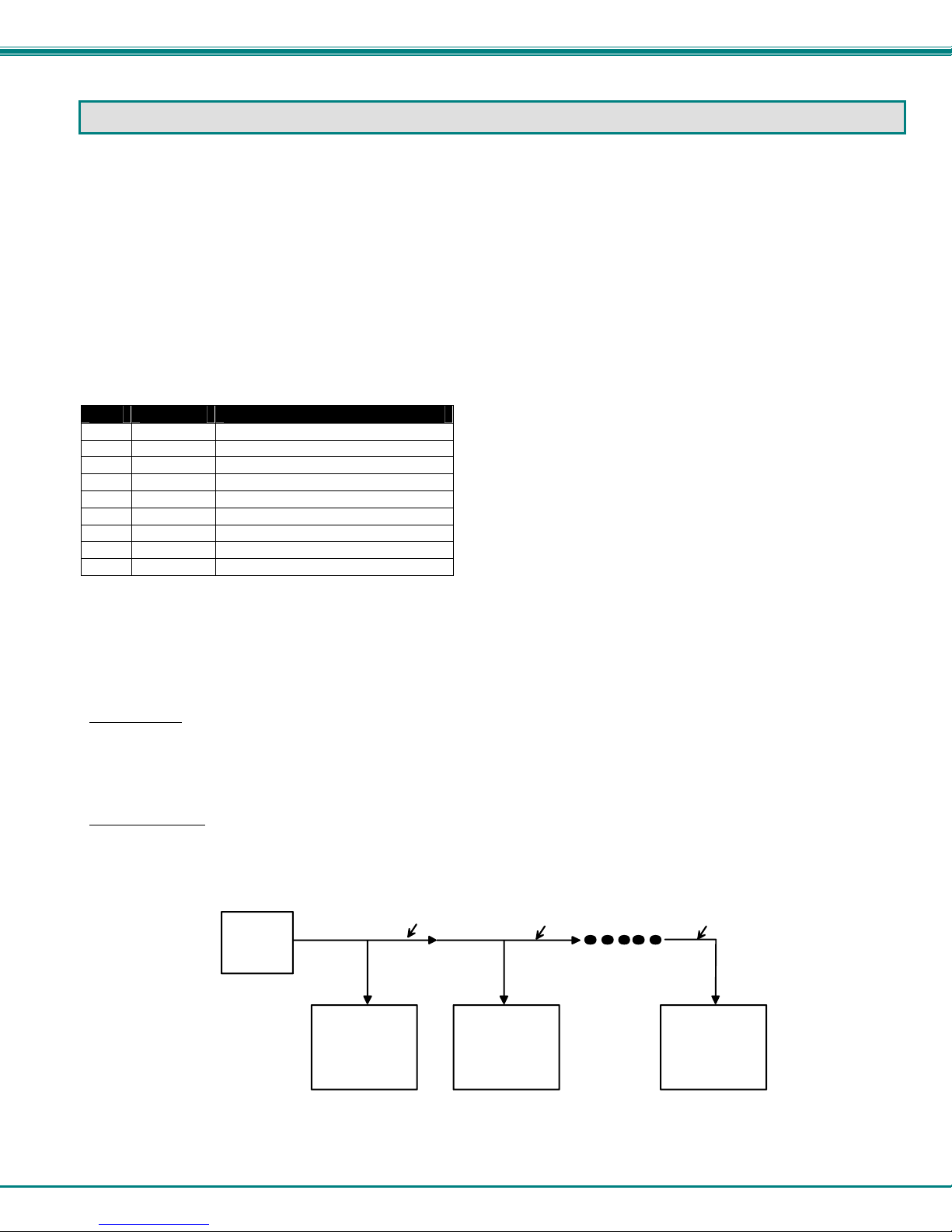
Remote Connection
The RS232 Interface is designed to control the switch via serial (RS232) daisy chain connection from any host computer or other
controller with an RS232 communications port.
The pin outs for the DB-9 connector on the unit are as follows:
RS232 Connector (DB-9 FEMALE)
PIN SIGNAL FUNCTION
1 None no connection
2 TXD Transmit Data (RXD at host)
3 RXD Receive Data (TXD at host)
4 DSR Data Set Ready
5 GND Signal Ground
6 DTR Data Terminal Ready
7 CTS Clear to Send
8 RTS Request to Send
9 None no connection
On the DB-9 female connector, pins 4 (DSR) and 6 (DTR) are shorted and pins 7 (CTS) and 8 (RTS) are shorted. T herefore, host
handshaking is bypassed and TXD and RXD are the only active signals. A straight through DB-9 cable (not null modem) will work
for most CPUs. To daisy chain multiple units, use NTI Matrix-Y-1 "Y" cables, except for the last unit connected. (see Fig 6). For a
pinout of the Matrix-Y-1 cable, see page 45. For straight through cable pinouts applicable to various terminal types, see page
44.
Baud Rate
The unit powers up with a default baud rate of 9600 and a fixed data protocol of 8 data bits, no parity and 1 stop bit. The baud
rate is selectable through the "Baud Rate Menu". A data protocol of 8 data bits, no parity, and 1 stop bit is used in the daisy
chain communication.
Unit Address
To allow multiple units to be controlled from a single host port, the RS232 control interface is designed to allow "daisy chaining" up
to 15 units using the NTI Matrix-Y-1 "Y" cables. By setting the appropriate unit address with the keypad, each unit can be given a
unique address (1-15). Then the unit will only respond to commands on the bus if its address is embedded in the command. (See
Fig. 6.)
Host
CPU
Figure 6- RS232 Connections for Daisy-chain
RS232
Serial Port
RS232
NTI
SWITCH
First Unit
Matrix-Y-1
Matrix-Y-1 Matrix-Y-1
RS232
NTI
SWITCH
Second Unit
RS232
NTI
SWITCH
Last Unit
10

NTI VEEMUX AUDIO/VIDEO MATRIX SWITCH
Command Protocol
CPU controller commands supported by the unit are defined below. All commands must be terminated with a <CR> (carriage
return). When a command is sent, the entire string is echoed back along with a response from the addressed unit as shown in the
Command Definitions table (below). All characters in the command string are case sensitive (see Command Definiti ons table),
and all numbers below 10 must have a leading 0 (ex: 1 = 01).
Legend:
(All numbers must be two digits)
SW : Switch (01-15)
BR : Baud Rate Code (12,24,48,96)
VV : Volume Level (00-99, XX=UNSUPPORTED)
OP : Output Port (01-MAXOUTPUTS)
MU : Mute State (00=UNMUTE, 01=MUTE,
XX=UNSUPPORTED)
Command Definitions
Command String Good Response Description
CS SW,IP,OP *<CR> VIDEO Connect One Output/User Port To Input/CPU Port
CA SW,IP *<CR> VIDEO Connect All Output/User Ports To Input/CPU Port
RO SW,OP *<CR>IP<CR> VIDEO Read Connection For Output/User Port
AS SW,IP,OP *<CR> AUDIO Connect One Output/User Port To Input/CPU Port
AA SW,IP *<CR> AUDIO Connect All Output/User Ports To Input/CPU Port
AO SW,OP *<CR>IP<CR> AUDIO Read Connection For Output/User Port
AM SW,OP,MU *<CR> Set Mute State For Output/User Port
AV SW,OP,VV *<CR> Set Volume Level For Output/User Port
CC SW,MM *<CR>MM<CR> Save Matrix Connections Into Memory Bank xx
RC SW,LL *<CR>LL<CR> Restore Matrix Connections From Memory Bank
CB 00,BR None Change baud rate of serial line, BR=12(00),24(00),48(00),96(00)
RS SW *<CR> Internal Reset
RV SW,00 *<CR>string\0<CR> Read NTI Version String
RU SW *<CR>IP,OP<CR> Read Unit Size
AR SW,OP *<CR>MU,VV<CR> Read Mute, Volume For Output/User Port
MU is 00 if the port is UNMUTED, MU is 01 if the port is MUTED.
VV is a value between 00 to 99 (see chart page 12)
EA SW,ip *<CR> Set the IP address, ip is in xxx.xxx.xxx.xxx format,
number of digits is minimum 1 and maximum 3 for each field
EM SW,ip *<CR> Set the Subnet mask, ip is in xxx.xxx.xxx.xxx format,
number of digits is minimum 1 and maximum 3 for each field.
EG SW,ip *<CR> Set the default gateway, ip is in xxx.xxx.xxx.xxx format,
number of digits is minimum 1 and maximum 3 for each field
ET SW,timeout *<CR> Set the website timeout; timeout = numeric string of timeout in
Values: 60, 300, 600, 900, 1800, 3600, 7200, 18000, 28800
RA SW * <CR>ip<CR> Read the IP address, ip is in xxx.xxx.xxx.xxx format,
number of digits is minimum 1 and maximum 3 for each field
RM SW * <CR>ip<CR> Read the Subnet mask, ip is in xxx.xxx.xxx.xxx format,
number of digits is minimum 1 and maximum 3 for each field
RG SW * <CR>ip<CR> Read the default gateway, ip is in xxx.xxx.xxx.xxx format,
number of digits is minimum 1 and maximum 3 for each field
IP : Input Port (01-MAXINPUTS)
MM : Save Into Memory Bank (00-99)
LL : Load From Memory Bank (00-99)
<CR> : Carriage Return (Hex 0xD)
ip : IP address
AP : Audio Port
See chart on page 12 for values
Xx=00-99
Factory default is 9,600
Leading zeroes are accepted
Leading zeroes are accepted
Leading zeroes are accepted
seconds.
Leading zeroes are accepted
Leading zeroes are accepted
Leading zeroes are accepted
11
 Loading...