

NTI SERIMUX-S-x Installation And Operation Manual

®
SERIMUX
Series
SERIMUX-S-x
SECURE SSH CONSOLE SERIAL SWITCH
Installation and Operation Manual
MAN107 Rev 2/27/14

TRADEMARK
SERIMUX is a registered trademark of Network Technologies Inc in the U.S. and other countries.
COPYRIGHT
Copyright © 2009, 2014 by Network Technologies Inc. All rights reserved. No part of this publication may be reproduced, stored
in a retrieval system, or transmitted, in any form or by any means, electronic, mechanical, photocopying, recording, or otherwise,
without the prior written consent of Network Technologies Inc, 1275 Danner Drive, Aurora, Ohio 44202.
This product contains software licensed under the GNU Public License version 2 and other open source licenses.
( http://www.gnu.org/copyleft/gpl.html
You may obtain the complete open-source code free of charge from Network T echnolog ies Inc (send email to techconsult@ntigo.com) for more information.
)
CHANGES
The material in this guide is for information only and is subject to change without notice. Network Technologies Inc reserves the
right to make changes in the product design without reservation and without notification to its users.
FIRMWARE VERSION
Current Firmware Version 1.40
CE Statement
We, Network Technologies Inc, declare under our sole responsibility that the SERIMUX-S-4/8/16/24/32 are in conformity with
European Standard EN55022.
Typographic Conventions
The table below offers examples of text format and the meaning when that format is used when the font varies from the standard
font (Helvetica) used in this manual.
Typeface meaning Font Configuration Example
On-screen computer output Courier New-(not bold)
What you type on the computer Courier New-bold
Characters to be typed as
instructed within the body of a
paragraph
Place holder-description of
other data to enter
i
C:>
C:>edit text.bat
Courier New-bold
Surrounded by < > <L>
Helvetica-Italic
Hostname

TABLE OF CONTENTS
Introduction....................................................................................................................................................................1
Serial Interface Specifications.....................................................................................................................................1
Network Interface ........................................................................................................................................................1
RJ45 Sensor Ports ......................................................................................................................................................1
Protocols......................................................................................................................................................................2
Supported Web Browsers ...........................................................................................................................................2
Definitions....................................................................................................................................................................2
Materials......................................................................................................................................................................3
Default User Name and Password...............................................................................................................................4
Features and Functions................................................................................................................................................5
Installation......................................................................................................................................................................6
To Mount to a Rack.....................................................................................................................................................6
Cable Connections......................................................................................................................................................7
Connect to the Ethernet ..............................................................................................................................................7
Dual Power Option ......................................................................................................................................................8
DC Power Option.........................................................................................................................................................8
Connect Sensors.........................................................................................................................................................9
Initial Startup ...............................................................................................................................................................10
Connect Direct to Serial Port from Command Line ................................................................................................13
Connect Via Telnet..............................................................................................................................................13
Connect Via SSH.................................................................................................................................................13
Using the SERIMUX Console Switch.........................................................................................................................14
Serial Control- Administrator.....................................................................................................................................14
Login as the administrator.........................................................................................................................................15
Port Management......................................................................................................................................................16
Common Settings................................................................................................................................................17
Port Settings ...........................................................................................................................................................17
Serial Settings.........................................................................................................................................................18
Port Logging............................................................................................................................................................19
Modem Setting........................................................................................................................................................20
Authentication.........................................................................................................................................................20
Event Notification....................................................................................................................................................21
Port Access List......................................................................................................................................................22
Port Disconnect.......................................................................................................................................................23
Apply Common Settings.........................................................................................................................................24
Device Management .................................................................................................................................................25
Add a Contact Sensor.............................................................................................................................................25
Remove a Sensor...................................................................................................................................................26
Configure a Sensor.................................................................................................................................................26
Sensor Settings...................................................................................................................................................27
Alert Settings.......................................................................................................................................................28
Data Logging.......................................................................................................................................................29
ii

Sensor Access List..............................................................................................................................................29
Sensor Authentication .........................................................................................................................................30
Network Management...............................................................................................................................................31
IP Configuration......................................................................................................................................................31
Server Configuration...............................................................................................................................................33
SNMP..................................................................................................................................................................35
TCP Setting.............................................................................................................................................................35
Administration Settings..............................................................................................................................................36
Unit Settings............................................................................................................................................................36
Unit Setting->Change Admin Password..............................................................................................................36
Unit Settings->Date Time Settings......................................................................................................................37
Security Settings.....................................................................................................................................................39
Syslog .....................................................................................................................................................................40
Firmware Update ....................................................................................................................................................42
User Management.....................................................................................................................................................44
System Users..........................................................................................................................................................44
Access Group .........................................................................................................................................................45
Administrative Info.....................................................................................................................................................46
System Log.............................................................................................................................................................46
System Information.................................................................................................................................................47
Network Information................................................................................................................................................47
Port List...................................................................................................................................................................48
Reboot.......................................................................................................................................................................48
Serial control-Users....................................................................................................................................................49
User Initial Selection Menu........................................................................................................................................49
Device Discovery Tool................................................................................................................................................51
Web Interface...............................................................................................................................................................52
Enter the Password ................................................................................................................................................52
Menu Overview..........................................................................................................................................................53
Main Menu and Port List ...........................................................................................................................................54
Connect to a Port....................................................................................................................................................54
Port Management......................................................................................................................................................57
Port Configuration...................................................................................................................................................57
Port Configuration->Port Settings .......................................................................................................................57
Port Configuration->Serial Settings.....................................................................................................................58
Port Configuration->Port Logging........................................................................................................................58
Port Configuration->View Port Log......................................................................................................................59
Port Configuration->Modem Settings..................................................................................................................59
Port Configuration->Authentication.....................................................................................................................59
Port Configuration->Event Notification................................................................................................................60
Port Configuration->Port Access List..................................................................................................................60
Port Configuration->Apply Common Settings .....................................................................................................60
Port Configuration->Disconnect Port...................................................................................................................61
Common Port Configuration Page..........................................................................................................................61
Copy Paste Port......................................................................................................................................................62
Base TCP Port.....................................................................................................................................................62
iii

Sensor Management.................................................................................................................................................63
Internal Sensors......................................................................................................................................................63
External Sensors.....................................................................................................................................................63
RS485 Sensors ...................................................................................................................................................63
RS485 Sensor Management...............................................................................................................................63
Sensor Summary....................................................................................................................................................63
Adding a Sensor .....................................................................................................................................................65
Configure a Sensor.................................................................................................................................................66
Sensor Settings...................................................................................................................................................67
Sensor Alert Settings...........................................................................................................................................67
Sensor Log Settings............................................................................................................................................68
Sensor Authentication .........................................................................................................................................68
Sensor Access List..............................................................................................................................................68
Network Management...............................................................................................................................................69
IP Configuration......................................................................................................................................................69
Server Configuration...............................................................................................................................................70
SNMP..................................................................................................................................................................71
TCP Settings...........................................................................................................................................................71
Administrative Settings..............................................................................................................................................72
Unit Settings............................................................................................................................................................72
Unit Settings->Admin Password..........................................................................................................................72
Unit Settings->Date and Time Settings...............................................................................................................73
Security Settings.....................................................................................................................................................74
Syslog .....................................................................................................................................................................75
Firmware Update ....................................................................................................................................................76
User Management.....................................................................................................................................................77
System Users..........................................................................................................................................................77
Access Groups........................................................................................................................................................79
Administrative Information.........................................................................................................................................80
System Log.............................................................................................................................................................80
System Information.................................................................................................................................................80
Network Information................................................................................................................................................81
Support......................................................................................................................................................................81
Reboot.......................................................................................................................................................................82
Logout........................................................................................................................................................................82
Telnet Or SSH Connection .........................................................................................................................................83
Telnet via HyperTerminal........................................................................................................................................83
Telnet via Command Prompt..................................................................................................................................83
RESET Button..............................................................................................................................................................84
Change Console Port Baud Rate...............................................................................................................................84
Interconnection Cable Wiring Method ......................................................................................................................85
Troubleshooting..........................................................................................................................................................85
Specifications..............................................................................................................................................................90
Index.............................................................................................................................................................................91
Warranty Information..................................................................................................................................................92
iv

Figure 1- Secure rack mount ears to switch.......................................................................................................................................6
Figure 2- Secure switch to a rack ......................................................................................................................................................6
Figure 3- Connect terminals and devices to SERIMUX Console Switch............................................................................................7
Figure 4- Connect the LAN to the SERIMUX.....................................................................................................................................7
Figure 5- Power connections for SERIMUX with Dual Power option .................................................................................................8
Figure 6- Power connections for SERIMUX with DC power option....................................................................................................8
Figure 7- Connect sensors to the SERIMUX .....................................................................................................................................9
Figure 8- SERIMUX Secure configuration menu via serial connection............................................................................................10
Figure 9- Submenu for Port Connect or Sensor Monitoring.............................................................................................................11
Figure 10- Port Connection menu....................................................................................................................................................11
Figure 11- Sensor Monitoring ..........................................................................................................................................................12
Figure 12- Serimux Secure Configuration menu..............................................................................................................................15
Figure 13- Port Management- complete ports list............................................................................................................................16
Figure 14- Port Management selections for Port 1 ..........................................................................................................................16
Figure 15- Port Management- configure common settings for most ports .......................................................................................17
Figure 16- Port Management- port settings for Port 1......................................................................................................................17
Figure 17- Port Management-serial settings for Port 1 ....................................................................................................................18
Figure 18- Port Management-port logging for Port 1 .......................................................................................................................19
Figure 19- Port Management-modem setting for Port 1...................................................................................................................20
Figure 20- Port Management-authentication for Port 1....................................................................................................................20
Figure 21- Authentication server configuration ................................................................................................................................21
Figure 22- Port Management- event notification for Port 1 ..............................................................................................................21
Figure 23- Port Management-port access list for Port 1...................................................................................................................22
Figure 24- Port Management-add users to access list.....................................................................................................................22
Figure 25- Port Management-add group to access list ....................................................................................................................22
Figure 26- Port Management- remove group from access list.........................................................................................................23
Figure 27- Port Management- disconnect Port 1.............................................................................................................................23
Figure 28- Port Management- apply common settings to Port 1......................................................................................................24
Figure 29- Device Management menu.............................................................................................................................................25
Figure 30- Adding a sensor..............................................................................................................................................................25
Figure 31- Remove a Sensor...........................................................................................................................................................26
Figure 32- Sensor configuration topics ............................................................................................................................................26
Figure 33- Sensor settings for temperature sensor..........................................................................................................................27
Figure 34- Sensor settings for water sensor....................................................................................................................................27
Figure 35- Sensor alert settings.......................................................................................................................................................28
Figure 36- Sensor Data Logging......................................................................................................................................................29
Figure 37- Sensor Access List.........................................................................................................................................................29
Figure 38- Sensor user authentication.............................................................................................................................................30
Figure 39-Network Management menu............................................................................................................................................31
Figure 40- Network Management-IP Configuration..........................................................................................................................31
Figure 41- Network Management-IPv4 settings...............................................................................................................................31
Figure 42- Network Management- IPv6 settings..............................................................................................................................32
Figure 43- Network Management-IPv6 manual IP assignment........................................................................................................32
Figure 44-Network Management- Server Configuration...................................................................................................................33
Figure 45- Network Management- Web Server settings..................................................................................................................33
v
TABLE OF FIGURES

Figure 46- Network Management- SMTP server settings................................................................................................................33
Figure 47- Network Management- NFS server configuration...........................................................................................................34
Figure 48- Network Management-SNMP configuration....................................................................................................................34
Figure 49- Network Management-TCP settings...............................................................................................................................35
Figure 50- Administration Settings...................................................................................................................................................36
Figure 51- Administration Settings-Unit Settings .............................................................................................................................36
Figure 52-Unit Settings-change password.......................................................................................................................................37
Figure 53- Unit Settings-manual date and time................................................................................................................................37
Figure 54-Unit Settings-NTP Server settings...................................................................................................................................38
Figure 55- Unit Settings-Daylight Savings .......................................................................................................................................38
Figure 56- Administration Settings-Security Setting.........................................................................................................................39
Figure 57- Administration Settings-CLI Authentication Types..........................................................................................................39
Figure 58- Administration Settings-Security-CLI Authentication ......................................................................................................40
Figure 59- Administrative Settings-Syslog.......................................................................................................................................40
Figure 60- Administration Settings-System Log settings..................................................................................................................41
Figure 61- Administration Settings-Syslog-ng Configuration............................................................................................................41
Figure 62- Administration Settings-Firmware Update ......................................................................................................................42
Figure 63- Change path from tftp source to flash drive....................................................................................................................42
Figure 64- Firmware update- confirm to perform update..................................................................................................................43
Figure 65- Firmware update- Completed.........................................................................................................................................43
Figure 66- User Management menu................................................................................................................................................44
Figure 67- User Management- System Users..................................................................................................................................44
Figure 68- User Management-Configure User.................................................................................................................................44
Figure 69- User Management-Access Groups.................................................................................................................................45
Figure 70- User Management- Group User List...............................................................................................................................45
Figure 71- Administrative Info menu................................................................................................................................................46
Figure 72- Administrative Info-System Log......................................................................................................................................46
Figure 73- Administrative Info-System Information..........................................................................................................................47
Figure 74- Administrative Info-Network Information.........................................................................................................................47
Figure 75- Administrative Info-Port List............................................................................................................................................48
Figure 76- Reboot the SERIMUX from the shell..............................................................................................................................48
Figure 77- Initial menu for users......................................................................................................................................................49
Figure 78- A user with limited host port access ...............................................................................................................................49
Figure 79- Sensor list with current readings.....................................................................................................................................50
Figure 80- Device Discovered..........................................................................................................................................................51
Figure 81- Web interface Login page..............................................................................................................................................52
Figure 82- Connect Port/Port List Page...........................................................................................................................................54
Figure 83- SSH Port connection via Java Applet.............................................................................................................................55
Figure 84- SSH Port connected.......................................................................................................................................................55
Figure 85- Serial connection-"offline"-properly exited......................................................................................................................56
Figure 86- Port Configuration page..................................................................................................................................................57
Figure 87- Port Settings...................................................................................................................................................................57
Figure 88- Serial Settings ................................................................................................................................................................58
Figure 89- Port Logging settings......................................................................................................................................................58
Figure 90- View or Clear Port Log ...................................................................................................................................................59
Figure 91- Modem settings..............................................................................................................................................................59
Figure 92- Authentication method options .......................................................................................................................................59
Figure 93- Port event notifications ...................................................................................................................................................60
Figure 94- Port Access List..............................................................................................................................................................60
Figure 95- Apply common settings to port .......................................................................................................................................60
vi

Figure 96- Disconnect Port button ...................................................................................................................................................61
Figure 97- Common Port Configuration page..................................................................................................................................61
Figure 98- Copy Paste Port page ....................................................................................................................................................62
Figure 99- Sensor Summary page...................................................................................................................................................63
Figure 100- Sensor status details ....................................................................................................................................................64
Figure 101- Sensor Configuration page...........................................................................................................................................64
Figure 102-Add a sensor .................................................................................................................................................................65
Figure 103- Wiring method for contact sensor.................................................................................................................................65
Figure 104- Common Sensor Configuration page ...........................................................................................................................66
Figure 105- IP Configuration page...................................................................................................................................................69
Figure 106- Server Configuration Page ...........................................................................................................................................70
Figure 107- NFS Configuration settings...........................................................................................................................................71
Figure 108- TCP Settings page .......................................................................................................................................................71
Figure 109- Unit Settings page........................................................................................................................................................72
Figure 110- Change password for user "root"..................................................................................................................................72
Figure 111- Unit Settings page, date and time.................................................................................................................................73
Figure 112- Security Settings page..................................................................................................................................................74
Figure 113- Syslog page..................................................................................................................................................................75
Figure 114- Firmware Update page.................................................................................................................................................76
Figure 115- Firmware Update- file selected.....................................................................................................................................76
Figure 116- Firmware update done..................................................................................................................................................76
Figure 117- Firmware update failure................................................................................................................................................77
Figure 118- System User page........................................................................................................................................................77
Figure 119- User configuration ........................................................................................................................................................78
Figure 120- Access Groups page....................................................................................................................................................79
Figure 121- Edit user names listed in Access Group.......................................................................................................................79
Figure 122- System Log displayed ..................................................................................................................................................80
Figure 123- System Information page..............................................................................................................................................80
Figure 124- Network Information page.............................................................................................................................................81
Figure 125- Support Links................................................................................................................................................................81
Figure 126- Reboot page.................................................................................................................................................................82
Figure 127- Logout screen...............................................................................................................................................................82
Figure 128- Telnet connection via HyperTerminal ...........................................................................................................................83
Figure 129- Location of RESET button............................................................................................................................................84
Figure 130- View looking into RJ45 female......................................................................................................................................85
APPENDICES
Appendix A - SERIMUX Port Characteristics...................................................................................................................................86
Appendix B-SERIMUX User and Administrator Characteristics.......................................................................................................86
Appendix C- Cable Adapters ...........................................................................................................................................................87
Appendix D- Common Commands from Shell Command Line........................................................................................................89
Appendix E- SERIMUX-S-x Default Paths.......................................................................................................................................89
Appendix F- SERIMUX-S-x Default Network Settings .....................................................................................................................89
vii

NTI SERIMUX SERIES SSH CONSOLE SWITCH
INTRODUCTION
The NTI SERIMUX-S-x SSH Console Serial Switch (SERIMUX) is a serial port switch that delivers secure management of up to
32 serial devices via the internet, TCP/IP network, or dial-up modem connections. It combines the advanced sec urity o f Secure
Shell v2 with unlimited access to remote network management. The SERIMUX-S-x allows links (or connections) between multiple
pairs of RS232 asynchronous serial ports. The SERIMUX-S-x (x=4,8,16,24,or 32) is available with up to 32 serial port
connections.
The main purpose of the switch is to provide secure management of several serial devices from local or remote locations (using
Ethernet or external modems). Devices include routers, DSU's, servers, switches or any other equipment allowing serial
operation using RS232 interface. Users can work locally using a VT100 or ANSI serial console, a CPU with a terminal program
(i.e. HyperTerminal)) or from remote locations via Ethernet connection (Web Interface, SSH, Telnet).
Each SERIMUX port has to be configured for serial communication (baud rate, parity, etc) within the specifications of the attached
serial device, but the configurations of the two devices linked by the SERIMUX do not need to match. Various parameters
(communication speed, hardware and/or software flow control, timeout, etc) can be selected for each SERIMUX port. Devices
may be either locally connected or connected through attached modems.
Each SERIMUX port can be configured as either a host or user port. Serial hosts (such as servers, switches etc.) are connected to
host ports, while serial user devices (such as a terminal or serial console) are connected to user ports.
connections can be made to the same host port.
The SERIMUX supports two operator levels: user and administrator. Users may login and connect to serial devices attached at
host ports. The administrator and users with administrative privileges can see and/or modify various port or user parameters in
addition to connecting to serial devices attached at host ports.
Option:
• Dual AC Power Option- includes a second power connector for a secondary AC power supply cable- to order, add a
“DP” to the part number (i.e. SERIMUX-S-xDP)
• DC Power Option- SERIMUX designed for connection of 36-72VDC (48VDC nominal) for use in a Telecom
environment- to order add “-48V” to the part number (i.e. SERIMUX-S-x-48V)
• Dual DC Power Option- includes a second terminal block power connection for a secondary 48VDC power supply- to
order add a “-48VDP” to the part number (i.e. SERIMUX-S-x-48VDP)
Up to five (5) concurrent
Serial Interface Specifications
• Serial ports: 4,8,16,24 or 32 RJ45 RS232 serial port connections
• Console port: 1-RJ45 RS232 console port connector
• Data: asynchronous, 5, 6, 7, or 8 bits per character
• Parity: even, odd, or none
• Stop Bits: 1 or 2 bits
• Flow Control: Xon/Xoff, RTS/CTS, Both, or None
• Baud Rate: 50 bps to 115200 bps between ports
• Two connecting ports can be at different baud rates
Network Interface
• Two 10/100 Base-T Ethernet ports with RJ45 Ethernet connector
• Supports both static and dynamic IP addresses
RJ45 Sensor Ports
• Two RJ45 modular jacks for connecting NTI temperature, humidity, temperature/humidity, and liquid dete c tion sensors.
1

NTI SERIMUX SERIES SSH CONSOLE SWITCH
Protocols
• SSH V2, Telnet ,IPMI
• IPV4, IPV6
• TCP/IP, TFTP, DHCP, ICMP, UDP, ARP
• HTTP, HTTPS, SMTP, SNMP V1/V2c, Syslog, SMTP
• IPMI v2, RMCP
• Alerts are sent using email, and/or SNMP traps when any monitored environmental condition exceeds a user-specified
range or a serial port is connected or disconnected.
Supported Web Browsers
Most modern web browsers should be supported. The following browsers have been tested:
• Microsoft Internet Explorer 6.0 or higher
• Netscape 7.0 or higher
• Mozilla FireFox 0.9.2 or higher
Opera 9.0 or higher
•
Google Chrome 3.0 or higher
•
Set your browser to always check if there is a newer version of the page than the version stored in cache. This action will ensure
that it will display the most up-to-date information.
Definitions
device equipment that can transmit and/or receive data using RS232 interface
host serial device that performs a function or stores data to be controlled by a user
inactivity when a port is not receiving data from the device connected to it
terminal program a terminal emulation program- computer program that communicates via RS232 i nterface
(i.e. HyperTerminal)
"dumb" terminal serial terminal device or CPU terminal program that emulates a serial terminal
timeout time period of inactivity after which a port will be disconnected (the inter-port connection will be broken)
baud rate serial device or port receiver and transmitter speed; measured in "bps" (bits per second)
flow control a method to temporarily stop and restart serial data transfer (flow). It can be
- Hardware (out-band)- usually using the RTS and CTS physical handshaki ng signals;
- Software (in-band)- using special characters, usually named Xon and Xoff, inserted
in data being transferred;
- Both
2

NTI SERIMUX SERIES SSH CONSOLE SWITCH
Materials
Materials Supplied with this kit:
SERIMUX-S-x
IEC Power cord 5 Foot RJ45-to-
(country specific) RJ45 Cat5
(x2 with Dual AC Patch Cable
power option)
(6 feet of 22AWG 2-wire
cable provided for
models with DC
power connectors)
Rubber Feet
Rack mount ears kit
RJ45MF
Serial Crossover Adapter
Materials Required but not supplied:
Serial cable with at least one RJ45 male end for connection to the Console Switch from each device to be connected. See
Interconnection Cable Wiring Method on page 85 for cable pinout.
-
RS232-CO
Manual CD
Quick Start Guide and Administrator’s
Note
DB9F-RJ45F Serial Adapter
DB25M-RJ45F-C Modem Adapter
4-#10-32 X ¾” Pan Head Screws
4-#10-32 Cage Nuts
DB25F-RJ45F Console Adapter
DB25M-RJ45F-T Console Adapter
3

NTI SERIMUX SERIES SSH CONSOLE SWITCH
DEFAULT USER NAME AND PASSWORD
The default user name is root (lower case letters only).
The default password
is nti (lower case letters only).
4
NTI SERIMUX SERIES SSH CONSOLE SWITCH
FEATURES AND FUNCTIONS
NTI
Network Technologies Inc
R
PWR 1
PWR 2
P
W
R
1
2A,250V2A,250V
2
3
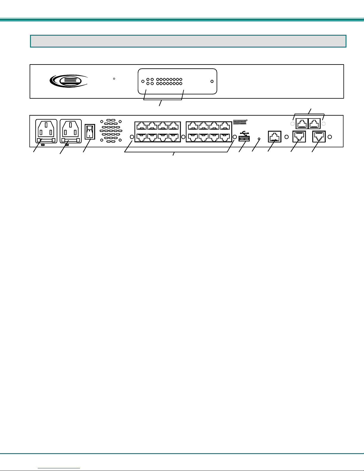
1. STATUS LEDs- LEDs will illuminate to indicate the SERIMUX is ON, activity on connected ports, or if there are alerts
2. PWR1- IEC Connector- for connection of AC power cord
3. PWR2- IEC Connector- for connection of second AC power cord for redundant power source (models with Dual AC Power
option only)
4. Power Switch- for turning the SERIMUX ON or OFF
5. Port connectors- RJ45 female serial connectors- for connecting serial cables from serial devices or user terminals
6. USB Devices- USB Type A female connector- for connecting USB flash drive for various data storage options
7. Reset button- For power cycling the SERIMUX firmware without powering down the SERIMUX
8. Console Port- RJ45 female serial connector- for connecting serial cable from a terminal console
9. Ethernet 1- RJ45 female connector- for connection of CAT5 cable to Local Area Network (LAN) for WEB interface
10. Ethernet 2- RJ45 female connector- for redundant connection of CAT5 cable to Local Area Network (LAN) for WEB
interface
11. RJ45 Sensors- RJ45 female connector- for connection of CAT5 cables to optional sensors
Front and Rear Views of SERIMUX-S-16DP
Ext
9 10111213141516Pwr
SERIMUX
R
SECURE
Alert
Int
234567810
Alert
1
AC INPUT
100-240VAC
15W
P
W
R
2
4
5
11
NTI
6
R
NETWORK
TECHNOLOGIES
INCORPORATED
RESET
7
1275 Danner Dr
Aurora, OH 44202
www.networktechinc.com
CONSOLE
8
Tel:330-562-7070
Fax:330-562-1999
9
910111213141516
12345678
RJ45 SENSORS
ETHERNET 2ETHERNET 1
10
5
NTI SERIMUX SERIES SSH CONSOLE SWITCH
INSTALLATION
This NTI switch was designed to be mounted to a rack or to set on a desktop. It includes rack mount ears to make attachment to
a rack easy, and rubber feet to be applied to the bottom of the case if it will instead sit on a flat surface. If this will sit on a flat
surface, simply apply the rubber feet to the bottom of the case in each of the 4 corners.
To Mount to a Rack
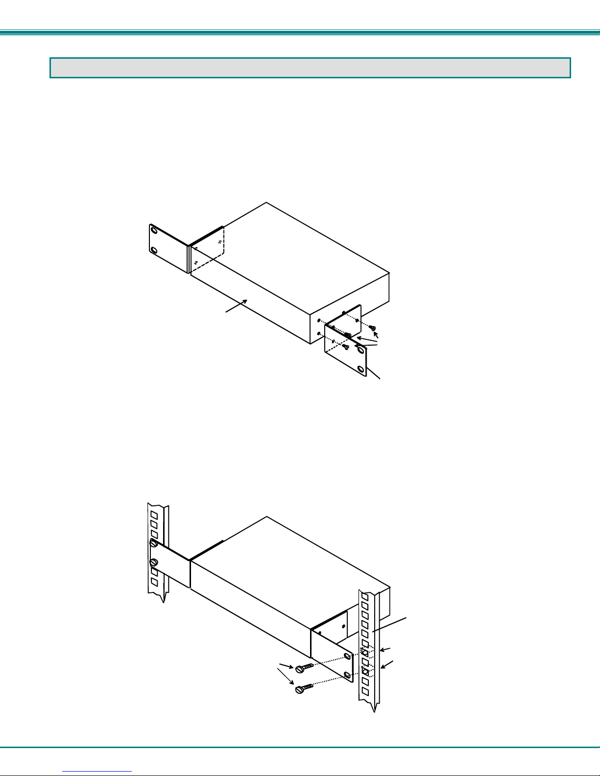
1. Attach the ears to the switch using the #6-32x3/16" flat Phillips-head screws (6) provided as shown in the illustration below.
The holes in the ears should line up with pre-threaded holes in the sides of the NTI switch. Tighten the screws securely.
Figure 1- Secure rack mount ears to switch
2. Install 4 cage nuts (supplied) to the rack in locations that line up with the holes in the mounting ear on the NTI switch.
3. Secure the NTI switch to the rack using four #10-32X3/4” screws (supplied). Each screw should be of sufficient length
to go completely through the NTI mounting ear, rack frame and fully engage all threads in the cage nut. Be sure to
tighten all mounting screws securely.
4. Attach all cables securely to the switch and where necessary supply adequate means of strain relief for cables.
Figure 2- Secure switch to a rack
Front of Switch
NTI Switch
#10-32x3/4"
Rack Screws
(supplied)
NTI Switch
6-32x3/16"
Flat Head
Screws
(supplied)
Rack mount ear
Rack
Cage Nuts
(supplied)
6
NTI SERIMUX SERIES SSH CONSOLE SWITCH
Cable Connections
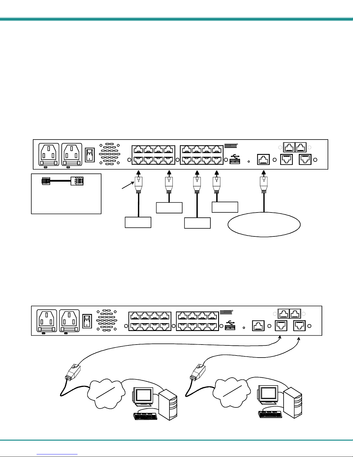
1. Connect a serial console to the port labeled "CONSOLE" on the SERIMUX using a serial cable with an RJ45 male connector
(Cat5 patch cable supplied). This will be the default administrator device. (Figure 3)
2. Connect each additional serial user device or host device to be connected by the SERIMUX to any remaining port (1-
4/8/16/24/32) using a serial cable with an RJ45 male connector (see cable specificati on on page 85). It may be necessary to
add one of the cable adapters (supplied) detailed in Appendix C (page 87) between the device port on the serial user device
or host device and the RJ45 connector. An NTI RJ45MF-RS232-CO serial crossover adapter has been provided for
connection of one DCE type device. More adapters can be purchased separately.
Note: There are two types of serial devices, data communication equipment (DCE)(i.e. modem) and data terminal
equipment (DTE) (i.e. CPU), each having different connector pin assignments. The cable adapters (see Appendix C on
page 87) make the proper connections.
3. Follow the "Initial Startup" instructions on page 10.
P
W
R
1
AC INPUT
PWR 2PWR 1
100-240VAC
15 W
P
W
R
2
2A,250V2A,250V
RJ45MF-RS232-CO
SERIAL CROSSOVER ADAPTER
(FOR CONNECTION OF DCE
TYPE DEVICE TO SERIMUX)
(Qty 1- supplied)
RJ45
Male
Connector
Ethernet cable
FIREWALL
Figure 3- Connect terminals and devices to SERIMUX Console Switch
Rear View of SERIMUX-S-16DP
8
567
ROUTER
4
SERVER
910111213141516
123
PBX
NTI
R
NETWORK
TECHNOLOGIES
INCORPORATED
RESET
1275 Danner Dr
Aurora, OH 44202
www.networktechinc.com
CONSOLE
Tel: 330 -562 -707 0
Fax:330-562-1999
USER DEVICE
(VT100, ANSI serial console ,
PC w/ Terminal Emulation
Program)
RJ45 SENSO RS
ETHERNET 2ETHERNET 1
RJ45 Male Connector
Connect to the Ethernet
If the Ethernet connection is made, the Web Interface (page 52) can be used. Up to two Ethernet connections to a Local Area
Network (LAN) can be made using Cat5 cable with RJ45 connectors attached. Wiring between connectors should be straight
through (pin 1 to pin 1, pin 2 to pin 2, etc.). Connect a Cat5 cable between the connector labeled "ETHERNET 1" and the LAN
(see Figure 4). For a redundant connection, attach a second Cat5 cable between the connector labeled “ETHERNET 2” and the
LAN.
RJ45 male
connector
Figure 4- Connect the LAN to the SERIMUX
PWR 2PWR 1
AC INPUT
100-240V AC
15 W
P
W
R
1
P
W
R
2
2A,250V2A,250V
LAN #1
Internet
Rear View of SERIMUX-S-16DP
16
8
131415
12
567
4
RJ45 male
connector
VGA
Multi-Scan
Monitor
User
with SSH
v2
7
91011
NTI
123
LAN #2
R
NETWORK
TECHNOLOGIES
INCORPORATED
RESET
Internet
1275 Danne r D r
Aurora, OH 44202
www.networ ktechinc. c om
CONSOLE
Tel:330-562-7070
Fax:330-562-1999
Multi-Scan
VGA
Monitor
RJ45 SENSORS
ETHERNET 2ETHERNET 1
User
with SSH
v2
NTI SERIMUX SERIES SSH CONSOLE SWITCH
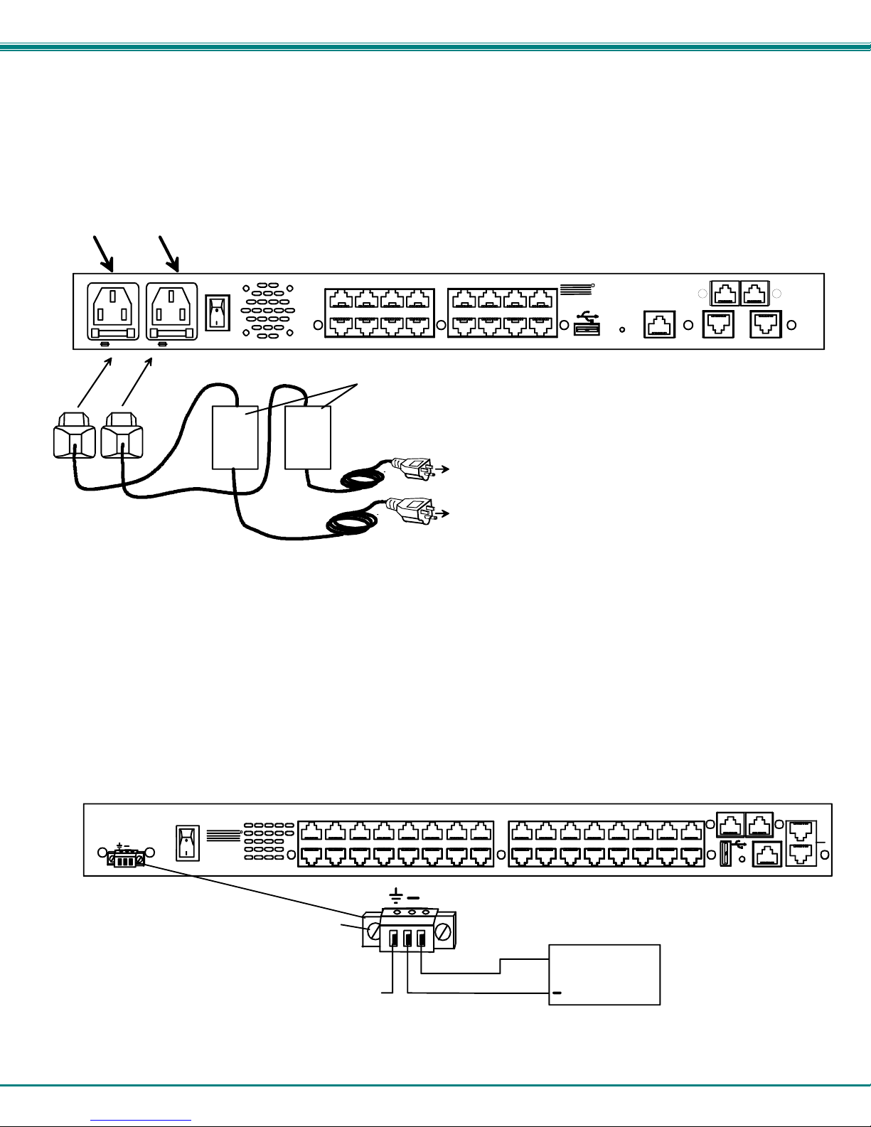
Dual Power Option
The SERIMUX-S-xDP has two IEC connectors on the rear, for connection to two separate power sources. If the power source
connected to “PWR 1” fails, the SERIMUX will automatically and without interruption switch over to the power source connected to
“PWR 2”.
Note: If only one power source is used, it should be connected to “PWR 1”.
PWR 1 PWR 2
PWR 1
PWR 2
AC INPUT
100-240VAC
P
W
R
1
15W
P
W
R
2
2A,250V2A,250V
UPS
1
UPS
2
Figure 5- Power connections for SERIMUX with Dual Power option
Rear View of SERIMUX-S-16D P
910111213141516
12345678
Uninterruptible Power Supplies
To Circuit #2
To Circuit #1
NTI
R
NETWORK
TECHNOLOGIES
INCORPORATED
RESET
1275 Danner Dr
Aurora, OH 44202
www.networktechinc.com
CONSOLE
Tel: 330- 562- 7070
Fax:330-562-1999
RJ45 SENSORS
ETHERNET 2ETHERNET 1
DC Power Option
The SERIMUX-S-x-48V has connections on the rear for a user-supplied 48VDC power supply. This is typically used when the
SERIMUX is installed in a Telecom environment. The SERIMUX-S-x-48V will accept a DC power source between 36~72VDC
(48VDC nominal), positive or negative polarity. A removable 3-pole screw terminal is prov ided for easy connection. The image
below shows a SERIMUX-S-32-48V, but is also available with dual 48VDC power connecti ons for a dual power supply option
(model SERIMUX-S-32-48VDP).
36-72VDC, 2A
+
NTI
1275 Danner Dr
Aurora, OH 44202
Tel:330-562-7070
Fax:330-562-1999
www. networ ktechi nc.com
R
32
31
16
Loosen screws to remove
terminal block
Chassis ground
Figure 6- Power connections for SERIMUX with DC power option
Rear View of SERIMUX-S-32- 48V
24
28
2930
12
131415
252627
91011
23
8
+
+
20
2122
4
567
48VDC
Power
Supply
RESET
CONSOLE
RJ45 SENS ORS
ETHERNET
171819
123
2
1
8

NTI SERIMUX SERIES SSH CONSOLE SWITCH
Connect Sensors
The SERIMUX-S-x has two RJ45 connectors for attachment of up to two sensors to monitor environmental conditions. Sensors
can be connected to measure temperature (ENVIROMUX-STS), humidity (ENVIROMUX-SHS), temperature and humidity
(ENVIROMUX-STHS), temperature and wide range humidity (ENVIROMUX-STHS-99). A sensor can also be connected to
detect liquids (ENVIROMUX-LDSx-y). All sensors are sold separately.
P
W
R
1
ENVIROMUX-STS
Temperature
Sensor
Figure 7- Connect sensors to the SERIMUX
AC INPUT
PWR 2PWR 1
100-240VAC
15W
P
W
R
2
2A,250V2A,250V
RJ45-male
connector
16
RJ45-male
connector
Cat5 cable
(up to 1000 ft)
Rear View of SERI MU X- S -1 6 DP
131415
12
91011
NTI
12345678
ENVIROMUX-LDSx-y
Liquid Detection
Sensor
RJ45-male
connector
R
NETWORK
TECHNOLOGIES
INCORPORATED
RESET
1275 Danner Dr
Aurora, OH 44202
www.networktechinc.com
CONSOLE
Tel:330-562-7070
Fax:330-562-1999
2-wire cable (up to 100 ft (y))
water sensor
Cat5 cable
cable (up to 1000 ft (x))
(up to 1000 ft)
RJ45 SENSORS
ETHERNET 2ETHERNET 1
RJ45-male
connector
9
NTI SERIMUX SERIES SSH CONSOLE SWITCH
INITIAL STARTUP
The following instruction will enable the user to quickly make port connections using a terminal connected to the
“CONSOLE” port. For instruction to make quick connection using the Ethernet port and Web Interface, see page 52.
1. Make sure the SERIMUX is turned OFF.
2. Using the serial console device connected to the port labeled "CONSOLE", start the terminal program (e.g. Windows
HyperTerminal) and configure it as follows:
• direct connection (using the appropriate CPU local serial Com port)
• 115200 bps
• 8 bits
• no parity
• 1 stop bit
• no flow control
• ANSI or VT100 terminal mode.
3. Power ON the SERIMUX. Wait for the SERIMUX login prompt.
4. At “login as: “ type <
5. At “password” type <nti> (all lowercase letters) and press <Enter>.
Note: If the administrator password has been changed and is not kno wn, contact NTI for instruction on resetting the
SERIMUX to defaults.
6. A shell prompt will be displayed “-sh-2.05b# “ . From this point you can either access the SERIMUX configuration menu,
or access a submenu for either making a port connection or viewing the status of connected sensors.
A. To access the configuration menu:
Type <serimuxconfig> to open Serimux Secure Configuration Menu. (See Figure 8) Use menu structure
to configure SERIMUX.
Figure 8- SERIMUX Secure configuration menu via serial connection
root> (all lowercase letters) and press <Enter>.
10

NTI SERIMUX SERIES SSH CONSOLE SWITCH
B. To make a connection with a host:
Type <portmenu> to open a submenu listing the “Port Connect Menu” and the “Sensor Monitor Men”.
Figure 9- Submenu for Port Connect or Sensor Monitoring
Enter <1> +<Enter> to proceed to the port connection menu.
Figure 10- Port Connection menu
Then type a port number and press <Enter> to make a connection with a host. (See Figure 10)
Enter <x> to return to the previous menu.
Note: To connect to a host, the host must first be configured with the same communi cation settings as the port (default
serial settings = 9600 baud, 8 bits, no parity, 1 stop bit, no flow control). If needed, see “Serial Settings” on page 18 to
change the SERIMUX port serial settings.
11

NTI SERIMUX SERIES SSH CONSOLE SWITCH
C. To view sensor status:
Type <portmenu> to open a submenu listing the “Port Connect Menu” and the “Sensor Monitor Men” (see Figure 9).
Enter <2> +<Enter> to proceed to the Sensor List.
Figure 11- Sensor Monitoring
From the Sensor Monitor menu you will view a list of all sensors monitored by the SERIMUX. From here you will be able to view
the current value being reported by the sensor and its alert status. If a sensor is reporting an alert, you can either press <a> to
acknowledge the alert, or <d> to dismiss the alert.
If the sensor is in alert status, the user has the option to either acknowledge the alert or dismiss it. If the user acknowledges
the alert, no additional alert messages will be sent during that alert status cycle. If the user dismisses the alert, another alert
message will be sent once the “notify again after” time designated on the configuration page elapses.
12

NTI SERIMUX SERIES SSH CONSOLE SWITCH
Connect Direct to Serial Port from Command Line
To connect directly to a serial port from the command line, the SERIMUX must first be connected to the Ethernet (page 7).
Connect Via Telnet
To open a telnet session to a serial port, Issue the following command from the command line:
telnet <Serimux-S hostname or IP address> <TCP port number>
<Serimux-S hostname> is the hostname configured in the workstation where the telnet client will run (through /etc/hosts or DNS
table). It can also be just the IP address of the SERIMUX.
<TCP port number> is the number assigned to the serial port. From the factory, 7001 corresponds to serial port 1, 7002 to serial
port 2 and so forth.
The user will be prompted for username and password to connect to the port/device (unless the device has no security).
Connect Via SSH
To open an SSH session to a serial port, issue the following command from the command line:
ssh -l <Username> <Serimux-S hostname or IP address> -p <Tcp port number>
<Username> is the user configured to access that serial port (as defined in the list of users in the device
<Serimux-S hostname> is the hostname configured in the workstation where the telnet client will run (through /etc/hosts or DNS
table). It can also be just the IP address of the SERIMUX.
<TCP port number> is the number assigned to the serial port. From the factory, 7001 corresponds to serial port 1, 7002 to serial
port 2 and so forth.
The user will be prompted for a password to connect to the port/host.
Note: Up to five (5) concurrent connections can be made to the same host port.
configuration).
13

NTI SERIMUX SERIES SSH CONSOLE SWITCH
USING THE SERIMUX CONSOLE SWITCH
The SERIMUX Console Switch is controlled using
• Serial Control- from a "dumb" terminal- locally-connected
- through an external modem from a remote location
- through a CPU connected to a “User” port
• Ethernet Connection (through a LAN or the Internet)
- using the Web Interface
- using Telnet or SSH client
Serial Control
The SERIMUX Console Switch can be easily configured using serial communications from either a locally-connected “dumb”
terminal, from a terminal remotely connected through a modem, or from a CPU connected to a port configured as a “User” port.
Using a keyboard-controlled menu, the user can make port connections or modify various parameters and options for each port.
Ethernet Connection
With an Ethernet connection to a LAN, the user can remotely control SERIMUX port configuration and connections. A user can
connect through the Web Interface menus (see page 52) or using a Telnet or SSH client.
SERIAL CONTROL- ADMINISTRATOR
Using serial control, the SERIMUX supports 2 operator levels, administrator and user, each with separate password prot ection for
security.
• The administrator logs in using an administrator password
administrator name : root (all lowercase letters)
administrator password : nti (all lowercase letters)
FYI: Users may be granted administrative access rights by any user with ad ministrative access rights.
The administrator and any user with administrative rights can:
Users with only “user” rights can only connect to host ports they have access to as defined by the root user or a user with
administrative access rights.
Throughout the SERIMUX Secure Configuration menu, the following guidelines apply:
Once changes are made, at the “INPUT” prompt;
If you press <x>-<Enter> without saving first, the message “Do you want to save and apply configuration (y/n):”
will appear. Press <y> to save and apply, press <n> to exit without saving. If you press <n> or anything but <y>, you will
receive the message “Nothing applied”.
If you press <x>-<Enter> without having made any changes, the message “Do you want to exit configuration
menu(y/n):” will appear. Press <y> to exit, or press <n> to be returned to the menu at which you were last. Pressing any
other key will cause the message “INVALID INPUT” and return you to the current menu.
Press <h>-<Enter> for topic specific help.
• Users login using a password set by the administrator or a user with administrative privileges.
• view / modify port parameters;
• view / modify user parameters and user access rights to ports;
• disconnect ports, logout users etc.
• connect to devices on all host ports
• fully configure the SERIMUX except change the “root” password (only the “root” user can change the “root”
password)
- press <s>-<Enter> to save them for application to the system on the next reboot
- press <p>-<Enter> to save and apply changes immediately
- press <Esc> to exit the menu and step back one menu
- press <x>-<Enter> to exit the SERIMUX Secure configuration menu
The administrator name cannot be
changed.
To change the administrator
password, see page 28.
14

NTI SERIMUX SERIES SSH CONSOLE SWITCH
Login as the administrator
1. From the user terminal connected to the “Console” port, open the terminal program (configured as described on p age 10
under "Initial Startup").
2. Power ON the SERIMUX. Wait for the SERIMUX login prompt.
3. At “login as: “ type <
4. At “password” type <
Note: This will only access the SERIMUX if the administrator password has not yet been changed from "nti".
Note: If the administrator password has been changed and is not kno wn, contact NTI for instruction on resetting the
SERIMUX to the default password “nti”.
5. A shell prompt will be displayed “-sh-2.05b# “
To access the configuration menu:
Type <serimuxconfig> to open Serimux Secure Configuration Menu. (See Figure 8) Use the menus
as described on the following pages to configure the SERIMUX.
Figure 12- Serimux Secure Configuration menu
FYI: Only a user with administrative rights can access the configuration menu. Otherwise, a user will login directly to
the Port Connect menu (Figure 11, page 12), with access to ports as defined by the administrator.
From the Serimux Secure Configuration menu, the following options are possible
Function Description Keystroke
Port Management Configure port settings <1>-<Enter>
Device Management Configure Sensor settings <2>-<Enter>
Network Management Configure Network settings <3>-<Enter>
Administration Settings Configure unit name, “root” password, security, and perform firmware update <4>-<Enter>
User Management Add, delete, and configure user settings; add, delete, setup access groups <5>-<Enter>
Administrative Info View syslog, firmware version, MAC addresses, network information <6>-<Enter>
Exit Exit connection with SERIMUX <x>-<Enter>
From any submenu, press <Esc> to exit and back out to the previous menu. Press <x>-<Enter> to exit configuration menu.
root> (all lowercase letters) and press <Enter>. A prompt requesting a password will appear.
nti> (all lowercase letters) and press <Enter>.
:
15
NTI SERIMUX SERIES SSH CONSOLE SWITCH
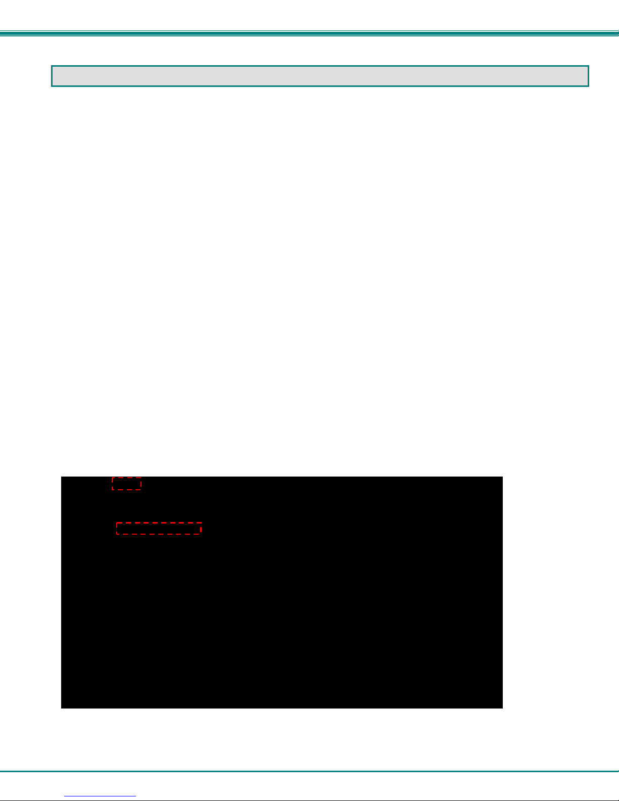
Port Management
From the Configuration menu, press <1> to open the “Port Management” menu.
Figure 13- Port Management- complete ports list
All ports, whether devices are connected to them or not, are listed in the Port Management menu. To make changes to a
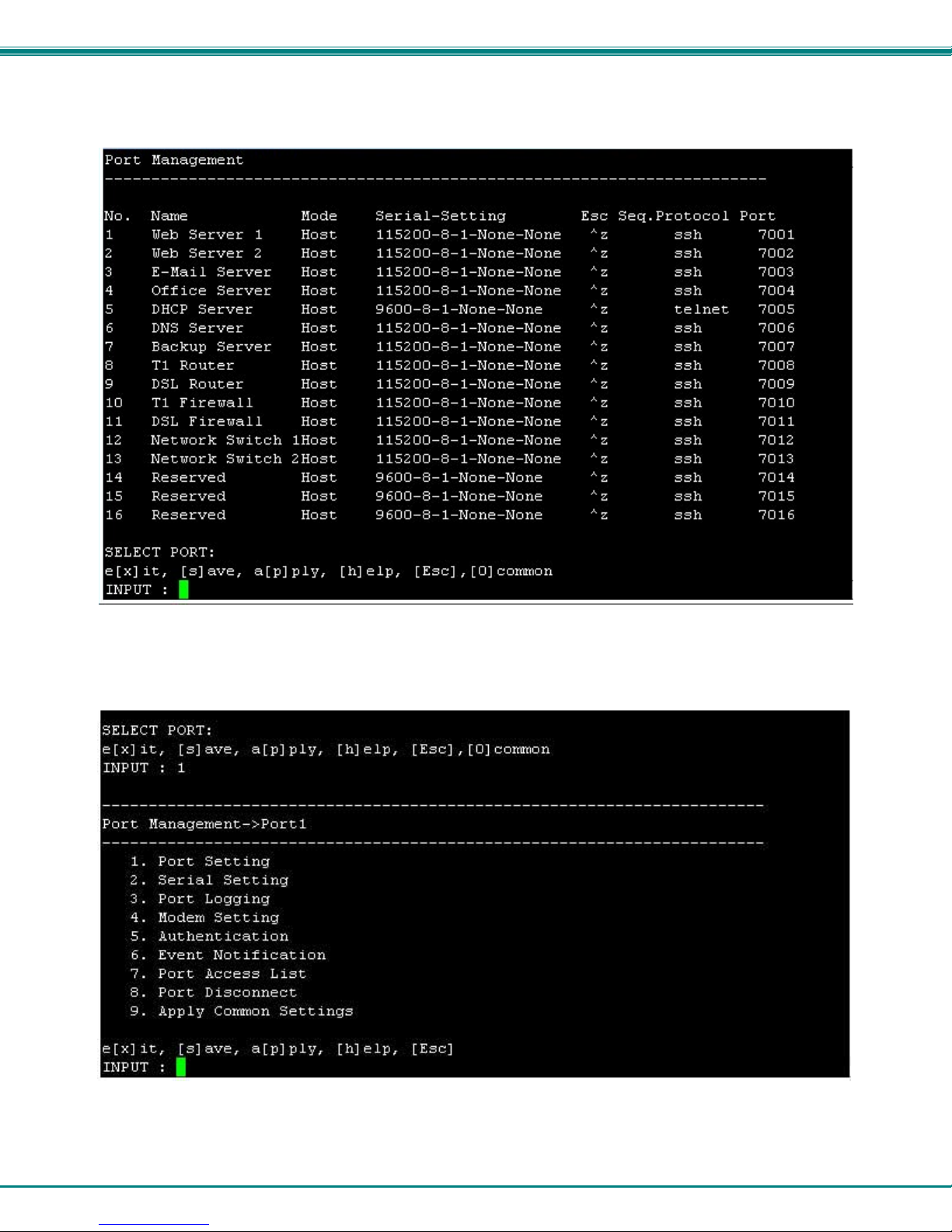
specific port’s configuration, enter the port number and press <Enter>. A menu of Port Management settings will appear.
Figure 14- Port Management selections for Port 1
To choose a category of settings to change, enter the number of the selection and press <Enter>.
16
NTI SERIMUX SERIES SSH CONSOLE SWITCH
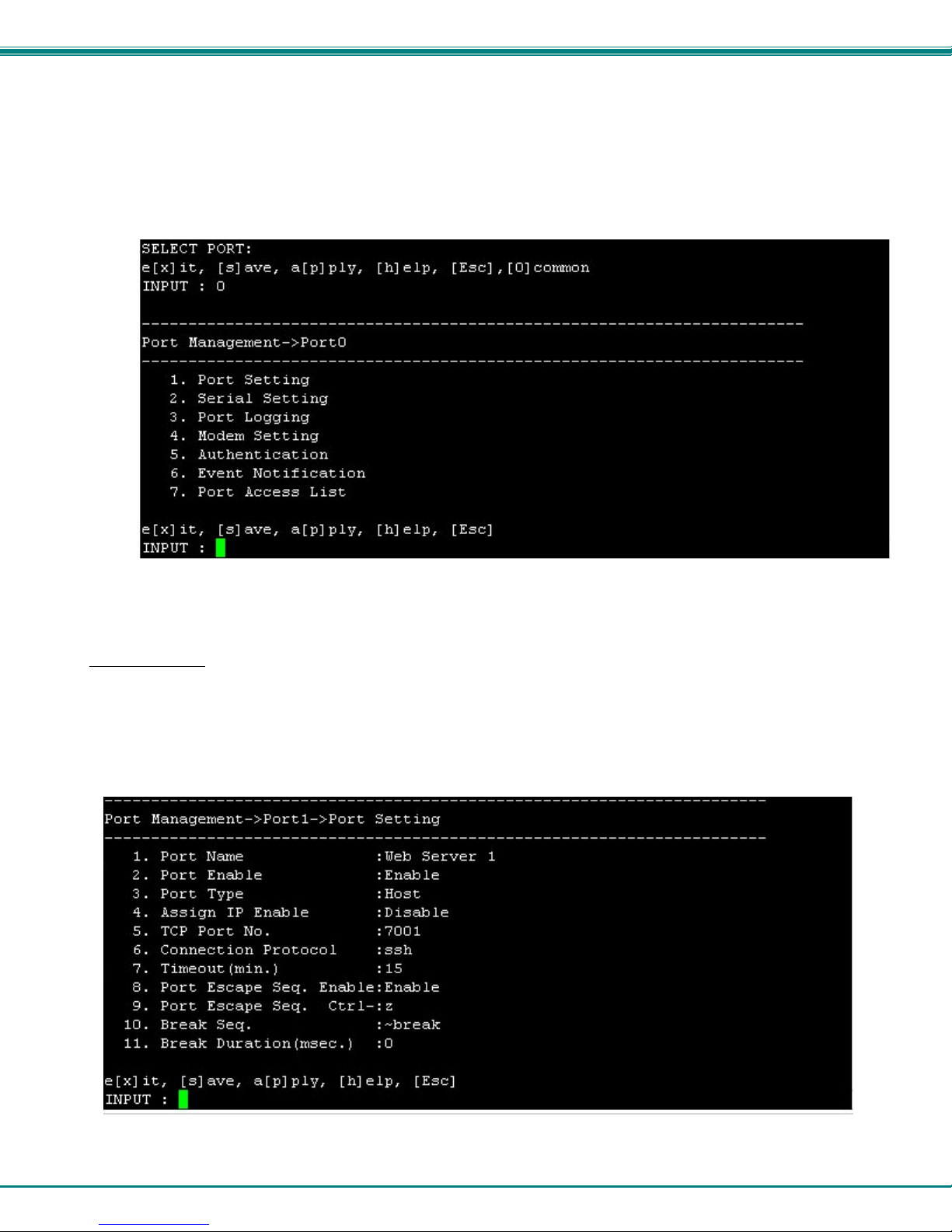
Common Settings
Before making changes to settings for specific ports, it would be quicker to apply settings to the “common” port, by pressing <o>
from the Port Management menu. This will open a menu (below) where the settings most common to the greatest number of
ports can be configured. With these configured, changing port settings for specific ports will be quicker by making the selection of
menu item 9-“Apply Common Settings” in the Port Management menu (page 24).
Figure 15- Port Management- configure common settings for most ports
Port Settings
From the Port Management menu, with Port x (any port) selected, press <1>-<Enter> to open the Port Setting menu.
Tip: Before configuring settings for Port 1-xx, configure common settings (top of page) and consider if
applying them to the selected port will save time (see also page 24).
Figure 16- Port Management- port settings for Port 1
17
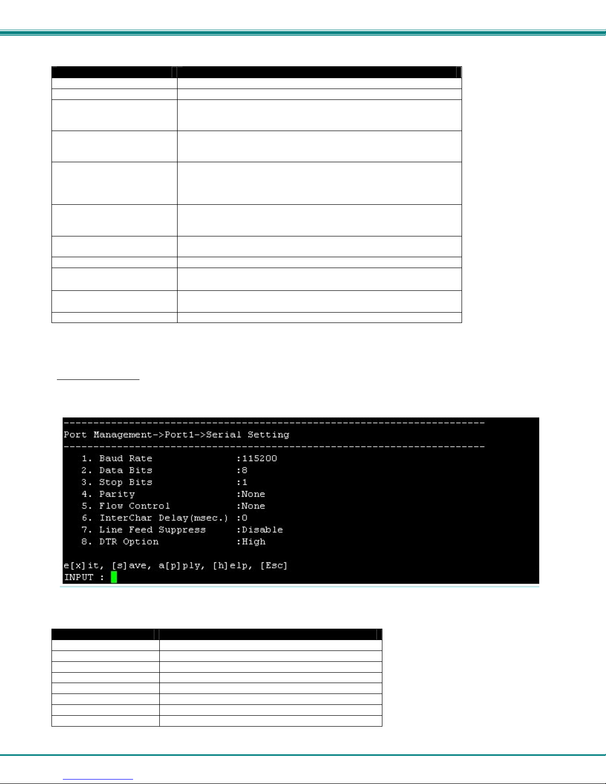
NTI SERIMUX SERIES SSH CONSOLE SWITCH
Setting Valid Entries
Port Name the name as it will appear in the port list- max. 50 characters.
Port Enable Enable or Disable. If disabled, no user can connect to it.
Port Type Host : for device connection
User: for direct user connection
Dial-in User: for connection via modem
Assign IP Enable When enabled, an IP address can be specifically assigned to this
port. Once enabled, the menu will refresh and an additional line will
be added to assign the IP address to be used.
TCP Port No. Assign number used for TCP communication
Be careful not to assign the same number used by another port,
or the second port with a duplicate TCP port assignment will not
work.
Connection Protocol Select: RawTCP for direct TCP connection
Telnet is using a Telnet client (non-secure connection)
SSH is using an SSH client (secure connection)
Timeout (minutes) set time (in minutes) before a port connection that is idle will be
automatically disconnected- range 0-999 minutes (0= disable)
Port Escape Seq. Enable Enable or disa ble the fu nction of using a port escape sequence
Port Escape Sequence Keyboard key to use in conjunction with the <Ctrl> key for a port
escape sequence. The default is <z>.
Break Sequence Sequence of characters which will send a break signal –
ie. <Ctrl>-<break>
Break Duration (msec.) Duration for which the break signal will be applied-range=0-999
Press <Esc> to exit and back out to the previous menu.
Serial Settings
From the Port Management menu, with Port x (any port) selected, press <2>-<Enter> to open the Serial Setting menu.
Figure 17- Port Management-serial settings for Port 1
Setting Value
Baud Rate 50bps-115.2Kbps (default = 9600)
Data Bits 5, 6, 7, or 8 (default = 8)
Stop bits 1 or 2 (default = 1)
Parity None, Even, or Odd (default = none)
Flow Control Hardware, Software, Both, or None (default = none)
Inter Character Delay 0-999 ms
Line Feed Suppress Enable or Disable
DTR Option High or Low
18
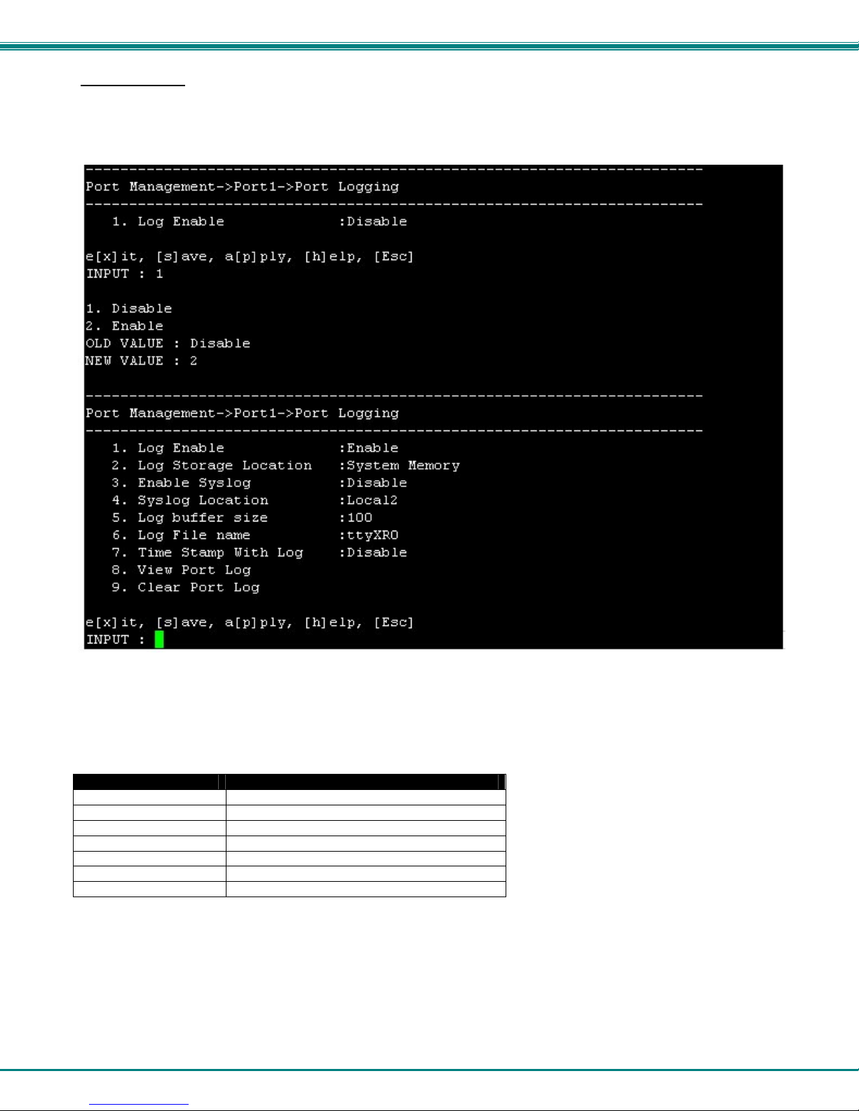
NTI SERIMUX SERIES SSH CONSOLE SWITCH
Port Logging
From the Port Management menu, with Port x (any port) selected, press <3>-<Enter> to open the “Port Logging” menu. Port
logging is used to record data received on the serial port.
Figure 18- Port Management-port logging for Port 1
Only 1 menu item will be displayed, indicating that port logging is disabled. Press <1>-<Enter> to be prompted for a new value.
Press <2>-<Enter> to enable port logging.
With port logging enabled, additional menu items will appear with the following s etting o ptions:
Setting Value
Log Enable Disable or Enable Logging feature for this port
Log Storage Location System Memory (cannot change at this time)
Enable Syslog Disable or Enable Syslog feature for port
Syslog Location Local
Log Buffer Size 0-999 (K bytes)
Log File Name up to 100 characters
Time Stamp With Log Enable to have log entries include a timestamp
Press <8> to view any current entries in the port log.
Press <9> to delete any entries in the port log for that port.
19
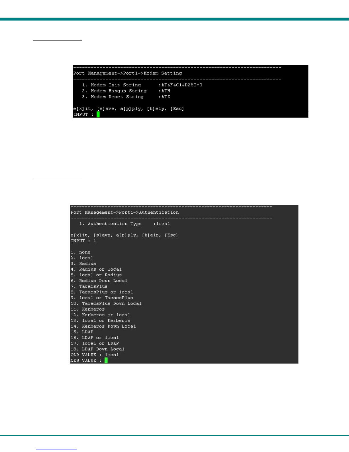
NTI SERIMUX SERIES SSH CONSOLE SWITCH
Modem Setting
From the Port Management menu, with Port x (any port) selected, press <4>-<Enter> to open the “Modem Setting” menu.
Figure 19- Port Management-modem setting for Port 1
If the port is set for a port type “Dial-In User” (see page 17), it will require a modem to be connected. Refer to your modem
instructions for appropriate settings to be applied here.
Authentication
From the Port Management menu, with Port x (any port) selected, press <5>-<Enter> to open the ”Authentication” menu.
Figure 20- Port Management-authentication for Port 1
From the menu (showing “1. Authentication Type”), press <1>-<Enter> to open a list of authentication options.
To disable authentication for that port, enter <1> for “none”. If the Authentication Type is set to “none”, then a user will not be
required to provide a username and password to access that port when connecting to it.
20
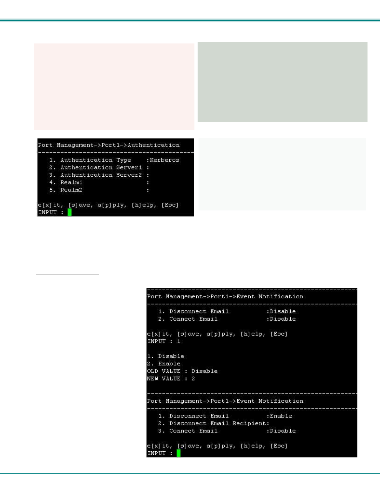
NTI SERIMUX SERIES SSH CONSOLE SWITCH
Authentication options that include Radius, TacacsPlus, Kerberos, and LDAP will require addition al configuration when selected.
Figure 21- Authentication server configuration
Apply the appropriate authentication server IP addresses and additional configuration settings for your authentication method of
choice.
Event Notification
From the Port Management menu, with Port x (any port) selected, press <6>-<Enter> to open the “Event Notification” menu.
From the Event Notification menu the
user can configure what email address to
send notice to when a port is
disconnected from, and provide a
separate email address (if desired) to
send notice of connection. Either or both
may also remain disabled (the default).
If the option is changed from “Disable” to
“Enable”, the menu will refresh and a
setting will be provided to enter an email
address to send notification to.
Figure 22- Port Management- event notification for Port 1
21
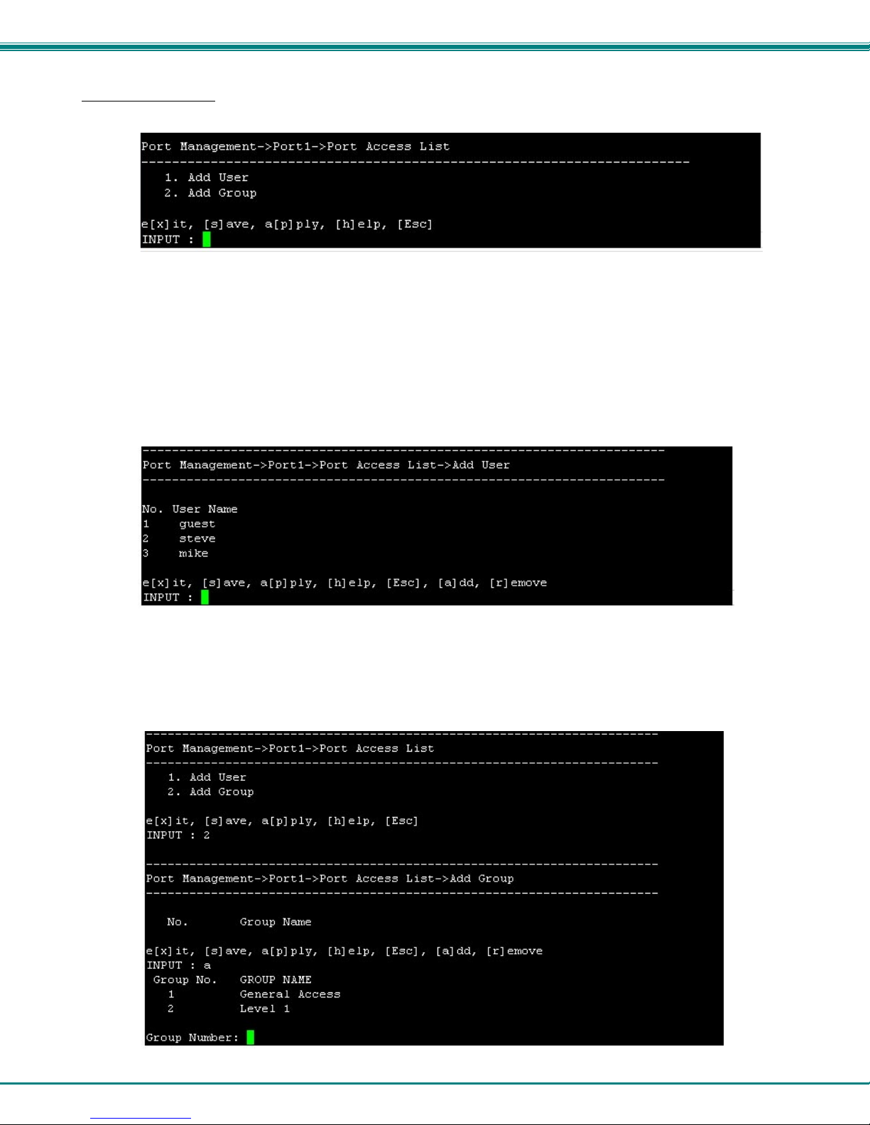
NTI SERIMUX SERIES SSH CONSOLE SWITCH
Port Access List
From the Port Management menu, with Port x (any port) selected, press <7>-<Enter> to open the “Port Access List”.
Figure 23- Port Management-port access list for Port 1
Each port can have individual user names and group names (pre-defined groups of users- see page 45) added to it that the
connected device will recognize as valid users. These names are not limited to the user names that can access the SERIMUX
menu. A user may connect to the SERIMUX using one name, and to a device with another. As long as the device recognizes the
name and password provided, access will be granted.
Note: Users and Groups defined in the Port Access List will only effect user access when the port is configured as a
“Host” port. When configured as a “User” port (page 17), all system users will have access to the SERIMUX through the
port.
Press <1> to be provided a prompt to add a user name.
Figure 24- Port Management-add users to access list
Options “add” and “remove” have been added to your choices. Press <a> to be prompted to enter a name to add to the user list,
or press <r> to be asked for the user number to remove from the list.
From the Port Access List menu (top of page), press <2>, then <a> (for add) to be shown the list of groups of users that have
been formed (page 45) and may be assigned access to that port.
Figure 25- Port Management-add group to access list
22
 Loading...