

NTI SE-15V-4-L, SE-15V-8-L, SE-15V-16-L, SE-AV-4-L, SE-AV-8-L Installation And Operation Manual
...
V
IDMUX®Series
SE-15V-xx-L/RS
SE-AV-xx-L/RS
4, 8, or 16 Port VGA Video-Only /
Audio-Video Switch
Installation and Operation Manual
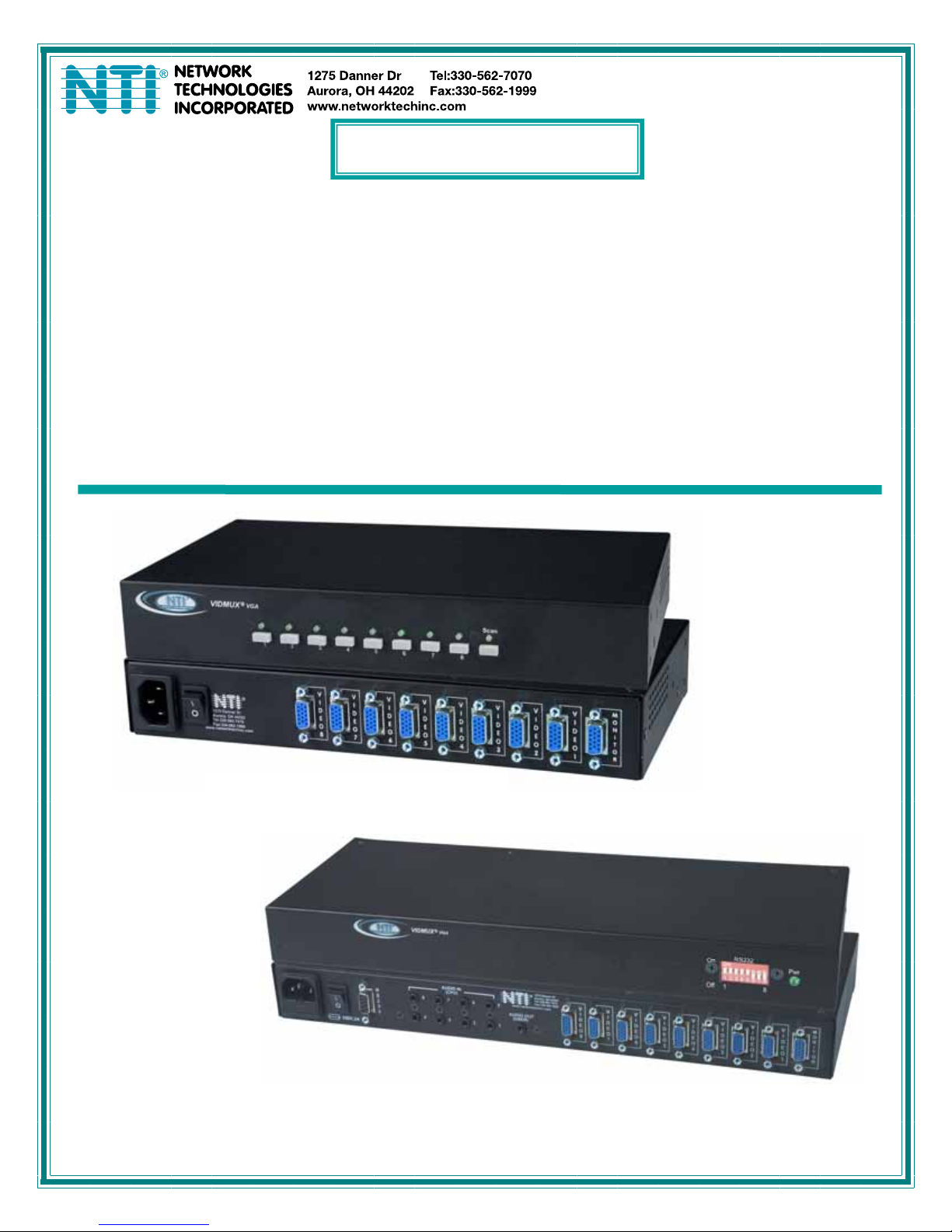
Front and Rear View of SE-15V-8-L
MAN004 Rev Date 3/11/2008
Front and Rear View of SE-AV-8-RS

TRADEMARK
VIDMUX is a registered trademark of Network Technologies Inc in the U.S. and other countries.
COPYRIGHT
Copyright © 1998, 2008 by Network Technologies Inc. All rights reserved. No part of this publication may be reproduced, stored
in a retrieval system, or transmitted, in any form or by any means, electronic, mechanical, photocopying, recording, or otherwise,
without the prior written consent of Network Technologies Inc, 1275 Danner Drive, Aurora, Ohio 44202.
CHANGES
The material in this guide is for information only and is subject to change without notice. Network Technologies Inc reserves the
right to make changes in the product design without reservation and without notification to its users.
i

TABLE OF CONTENTS
Introduction.................................................................................................................................................................... 1
Materials ...................................................................................................................................................................... 1
Features and Functions................................................................................................................................................ 2
Rack-Mounting ..............................................................................................................................................................3
To Mount to a Rack .....................................................................................................................................................3
Installation...................................................................................................................................................................... 4
Cable Connections ......................................................................................................................................................4
RS232 Control ..........................................................................................................................................................4
Audio Connections (SE-AV-xx-L/RS only)................................................................................................................ 5
Power Up Sequence.................................................................................................................................................... 5
Local Control ................................................................................................................................................................. 6
Scan Mode................................................................................................................................................................6
RS232 Control................................................................................................................................................................ 7
RS232 Connections and Configuration ....................................................................................................................... 7
Remote Connection .................................................................................................................................................. 7
Baud Rate ................................................................................................................................................................. 7
Unit Address .............................................................................................................................................................8
Loop Back Dipswitch ................................................................................................................................................8
Command Protocol ......................................................................................................................................................9
Autostatus ............................................................................................................................................................... 10
Scan Mode..............................................................................................................................................................10
NTI Switch Control Program For Windows 9X, NT, 2000, XP and Vista ..................................................................10
SerTest- RS232 Interface Test Program ................................................................................................................... 11
Main Options...........................................................................................................................................................11
Matrix Operations....................................................................................................................................................11
Setup Options ......................................................................................................................................................... 11
Audio Support .............................................................................................................................................................12
Specifications For Straight-Through RS232 Serial Cable.......................................................................................12
Technical Specifications ............................................................................................................................................12
Troubleshooting .......................................................................................................................................................... 13
Index ............................................................................................................................................................................. 14
Warranty Information .................................................................................................................................................. 14
TABLE OF FIGURES
Figure 1- Secure rackmount ears to switch........................................................................................................................................3
Figure 2- Secure switch to a rack ......................................................................................................................................................3
Figure 3- Make cable connections to the VIDMUX ............................................................................................................................4
Figure 4- Audio connections for VIDMUX with audio support ............................................................................................................ 5
Figure 5- View of Front of VIDMUX with Local Control ......................................................................................................................6
Figure 6- RS232 connection with Matrix-Y-1 cable............................................................................................................................8
Figure 7- Pinout of Matrix-Y-1 cable .................................................................................................................................................. 8
ii

NTI VIDMUX VGA Video-Only Switch
INTRODUCTION
The VIDMUX
plasma screen. VIDMUX Switches are made with either local video connection control with push buttons on the VIDMUX switch,
or with remote video connection control with an RS232 connection port on the VIDMUX switch.
Models covered by this manual include:
Legend:
-15V= Switches with video-only support
-AV= Switches with video and audio support
-L = Switches support local video connection control
-RS= Switch supports remote video connection control (RS232)
Features:
®
VGA video switch enables up to 4/8/16 video sources to be connected to a single video monitor, projector or
SE-15V-4-L SE-15V-8-L SE-15V-16-L SE-AV-4-L SE-AV-8-L SE-AV-16-L
SE-15V-4-RS SE-15V-8-RS SE-15V-16-RS SE-AV-4-RS SE-AV-8-RS SE-AV-16-RS
• Compatible with PCs, SUNs and MACs with VGA video.
• Eliminate redundant monitors.
• Ideal for classrooms and boardrooms.
• Interconnect NTI switches & splitters for complex applications.
• Crisp and clear 1900 x 1200 video resolution at 60Hz
Materials
Materials Included with this kit:
¾ NTI SE-15V-4/8/16-L/RS 4,8, or 16 port VGA Video-only Switch
or
¾ NTI SE-AV-4/8/16-L/RS 4,8, or 16 port VGA Audio-Video Switch
¾ Line cord- country specific
¾ VEXT-3-MM 3 foot 15HD male to 15HD male video cable
¾ SA-3-MM 3 foot 3.5mm plug-to-plug stereo audio cable (models with audio support only)
¾ 2- Rack-mount ears (4 and 8 port models only)
¾ 6- #6-32x3/16” screws (for attachment of ears on 4 and 8 port models)
¾ 4- rubber feet (4 and 8 port models only)
¾ CD with pdf file of this manual and RS232 Control Software (software only used in models with “-RS”)
1
NTI VIDMUX VGA Video-Only Switch
FEATURES AND FUNCTIONS
1a
R
R
VIDMUX
NTI
Network Technologies Inc
VGA
123456 78
12 3 4 5
250V,2A
2 3
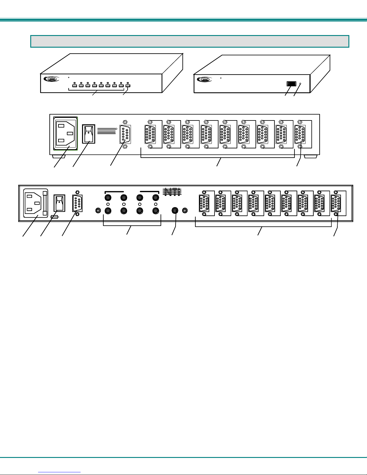
1. IEC Cord Connector- for attachment of the country-specific power cord
1a. IEC Connector w/Built-in 2A 240VAC Replaceable Fuse- for attachment of the country-specific power cord (only in
models with audio support)
2. Power switch- used to power the VIDMUX ON/OFF
3. RS232- 9DB female connector- for attachment of a serial cable for RS232 control (only on models ending in “-RS”)
4. Video-x- 15HD female connectors- for connection of video cable from video source(s)
5. Monitor- 15HD female connector- for connection of video cable from user monitor
6. CPU Buttons & LEDs- used to select and indicate connection to desired video source (only on models ending in “-L” )
7. Scan Button & LED- used to toggle Scan mode ON and OFF (only on models ending in “-L” )
8. RS232 Dip switches- for configuring RS232 control connection (only on models ending in “-RS”)
9. Pwr LED- to indicate power has been applied to the VIDMUX (only on models ending in “-RS”)
10. Audio IN (CPU)- 3.5MM Jack-for connection of audio cables from audio sources (only in
models with audio support)
11. Audio OUT (USER)- 3.5MM Jack- for connection of audio cables to audio output devices (speakers)(only in
models with audio support)
SE-15V-8-L
(Front View)
5678
67 89
R
NTI
1275 Danner Dr
Aurora, OH 44202
Tel:330-562-7070
Fax:330-562-1999
www.ne tworktechin c.com
R
S
2
3
2
8
Scan
REAR VIEW OF SE-15V-8-RS
R
S
2
3
2
V
I
D
E
O
8
REAR VIEW OF SE-AV-8-RS
AUDIO IN
(CPU)
10
NTI
www.networkt echinc.com
567
AUDIO OUT
(USER)
1234
11
V
I
D
E
O
7
R
1275 Danner Dr
Aurora, OH 44202
Tel:330-562-7070
Fax:330-562-1999
SE-15V-8-RS
(Front View)
R
R
VGA
VIDM UX
NTI
Network Technologies Inc
V
I
D
E
O
6
V
I
D
E
O
5
V
I
D
E
O
8
V
I
D
E
O
4
V
I
D
E
O
7
V
I
D
E
O
3
V
I
D
E
O
6
V
I
D
E
O
2
V
I
D
E
O
5
4
RS232
On
Pwr
Off
18
V
I
D
E
O
1
V
I
D
E
O
4
M
O
N
I
T
O
R
M
V
V
V
I
I
D
D
E
E
O
O
2
3
O
I
N
D
I
E
T
O
O
R
1
5
2
NTI VIDMUX VGA Video-Only Switch
RACK-MOUNTING
This NTI switch was designed to be mounted to a rack or to set on a desktop. It includes rackmount ears to make attachment to a
rack easy, and rubber feet to be applied to the bottom of the case if it will instead sit on a flat surface. If this will sit on a flat
surface, simply apply the rubber feet to the bottom of the case in each of the 4 corners.
To Mount to a Rack
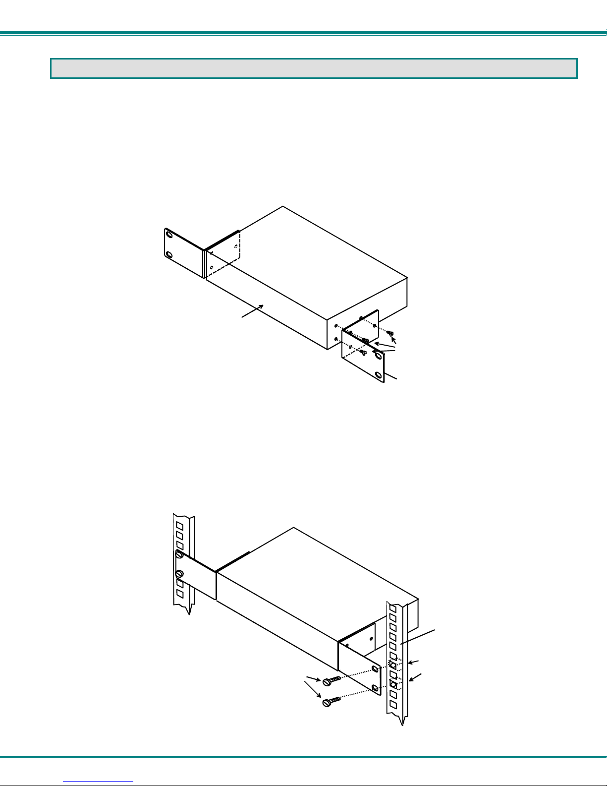
1. Attach the ears to the switch using the 6-32x3/16" flat Phillips-head screws (6) provided as shown in the illustration below.
The holes in the ears should line up with pre-threaded holes in the sides of the NTI switch. Tighten the screws securely.
Front of Switch
NTI Switch
6-32x3/16"
Flat Head
Screws
(Provided)
Rackmount Ear
Figure 1- Secure rackmount ears to switch
2. Install 4 captive nuts (not provided) to the rack in locations that line up with the holes in the mounting ear on the NTI switch.
3. Secure the NTI switch to the rack using four screws (typically #10-32 x ¾”- not provided). Each screw should be of sufficient
length to go completely through the NTI mounting ear, rack frame and fully engage all threads in the captive nut. Be sure to
tighten all mounting screws securely.
4. Attach all cables securely to the switch and where necessary supply adequate means of strain relief for cables.
Mounting Screws
(not provided)
NTI Switch
Rack
Captive Nuts
(not provided)
Figure 2- Secure switch to a rack
3
 Loading...