

Page 1

INSTALLATION GUIDE FOR THE 2-PORT TTL VIDEO ONLY SWITCH
SE-15V-2-2U1C-TTL / SE-15V-2-2C1U-TTL/SE-15V-2-2U1C-RS
INTRODUCTION
The NTI 2-port “TTL” controlled video only switch allows one (1) CPU to switch two (2) monitors (model SE-15V-2-2U1C-TTL) or
one (1) monitor to be switched to two (2) computers (model SE-15V-2-2C1U-TTL). All NTI 2-port "TTL" controlled video only
switches are available for VGA video with 150MHz bandwidth and 1920X1200 resolution.
Optional: RS232 Control instead of TTL control available in model SE-15V-2-2U1C-RS.
INSTALLATION
1. Turn OFF power to CPU(s) and monitor(s).
VGA
Multi-Scan
Monitor
EXISTING CABLE
REAR VIEW OF
SE-15V-2-2C1U-TTL
VIDEO 2
VIDEO 1
MONITOR
FOR MODEL SE-15V-2-2C1U-TTL
2a. Using the supplied video cable, connect the video port of one
CPU to the “VIDEO 1” port on the unit.
NOTE: It will be necessary to repeat this step on the
“VIDEO 2” port with another VEXT-xx video
VEXT-6
(supplied)
cable that must be purchased separately.
3a. Connect the monitor using its existing video cable to the
“MONITOR” port on the unit.
PC PC
Windows Keyboard & Mouse Windows Keyboard & Mouse
FOR MODEL SE-15V-2-2U1C-TTL/SE-15V-2U1C-RS
2b. Using the supplied video cable, connect the video port
of the CPU to the “VIDEO” port on the switch.
VGA
Multi-Scan
Monitor
3b. Connect the monitors using their existing video cables to
ports “MONITOR 1” and “MONITOR 2” on the switch.
EXISTING CABLE
NOTE: Using a VEXT-xx video cable the monitor cable(s)
can be extended up to 250 feet (sold separately).
VGA
Multi-Scan
Monitor
4. Secure the power cable to the cable tie on the SE-15V-2 and connect the power plug from the AC adapter to the SE-15V-2.
5. Plug in the AC adapter and power-up the switch. The “Power” LED and “1” LED should illuminate, indicating a conn ection
between the monitor and the CPU connected to “Video 1”.
6. Apply power to the CPU(s) and monitor(s).
VEXT-xx
REAR VIEW OF
SE-15V-2-2U1C-TTL
VIDEO MONITOR 1
MONITOR 2
VEXT-xx
PC
Windows Keyboard & Mouse
CABLE
RESTRAINT
5VDC
2.5A
+
-
CABLE
RESTRAINT
5VDC
2.5A
+
-
VEXT-6
(supplied)
1
Page 2
TTL Control (SE-15V-2U1C/2C1U-TTL Models Only)
Models with –TTL include a 9 pin D female connector port for remote control. The proper wiring of the 9DB connector to use this
port is as follows:
¾ Pin 1 = Ground
¾ Pin 2 = NC or connect toTTL1 (>2.4VDC) to switch to Monitor 1
¾ Pin 2 = Connect to pin 1 or TTL0 (<0.8VDC) to switch to Monitor 2.
The LEDs (1 or 2) will illuminate to provide indication of port selection
SE-15V-2-2C1U-TTL
FRONT VIEW
NTI
Network Technologies Inc
R
VIDMUX
R
VGA
Remote
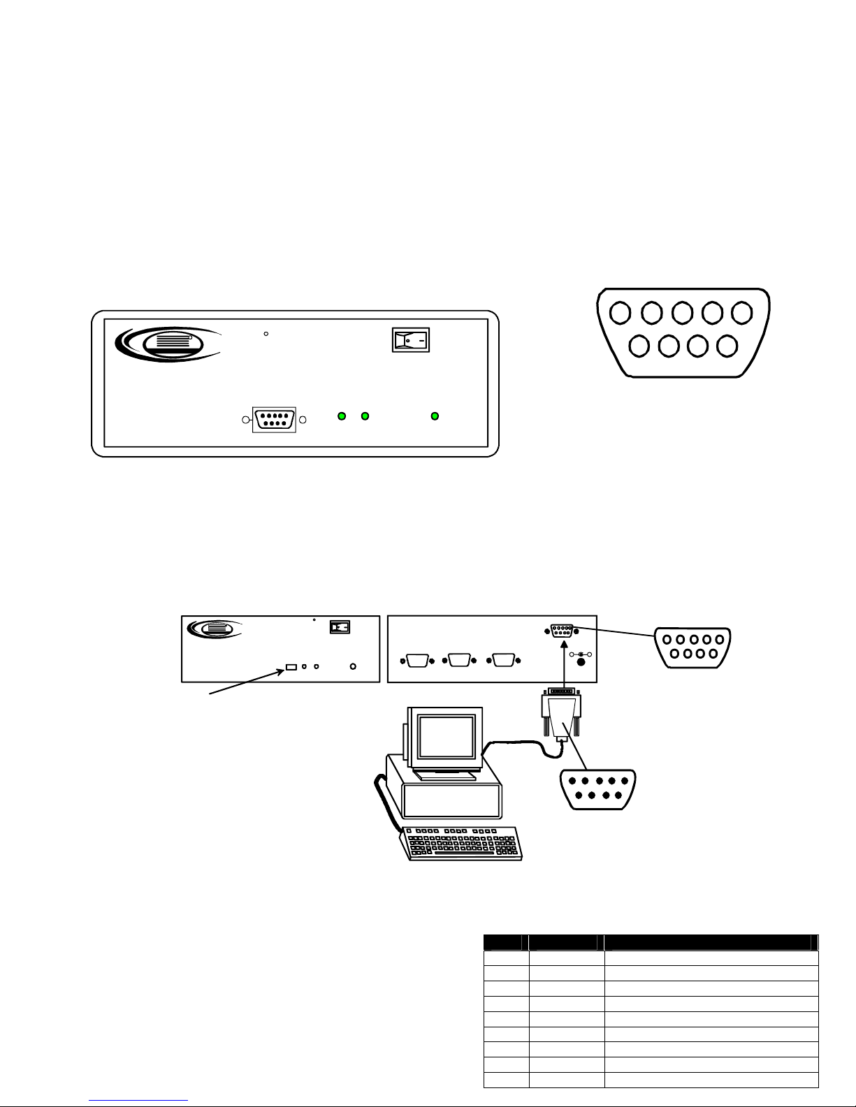
RS232 CONTROL (SE-15V-2U1C-RS Only)
The SE-15V-2U1C-RS can be controlled from the front panel push button (press to switch between MONITOR 1 and MONITOR2)
or it can be controlled using RS232. RS232 control can be achieved using a separate user terminal or CPU with a terminal
program. To make a terminal connection, connect a serial cable (specifications on page 3) between the user terminal and the 9
pin DIN female connector on the VIDMUX labeled "RS232". Configure the terminal program for a baud rate of 9600.
Push button to select
which monitor will
receive video from
CPU
Remote Connection
The RS232 Interface is designed to meet the RS232C standard
and can be controlled from any CPU or other controller with an
RS232 communications port. The pin-out for the 9DB connector
on the unit is as follows:
On the 9DB female connector, pins 1 (DCD), 4 (DTR), and 6
(DSR) are shorted and pins 7 (RTS) and 8 (CTS) are shorted.
Therefore, host handshaking is bypassed and TXD and RXD are
FRONT VIEW OF
SE-15V-2-2U1C-RS
R
NTI
Network Technolo gies I nc
Select
VIDMUX
1
1
2345
1
2 Power
6
Mating Face
8
7
9
of a 9DB Male
REAR VIEW OF
R
VGA
Power
2
SE-15V-2-2U1C-RS
MONITOR 2
VGA
Multi-Scan
Monitor
VIDEO MONITOR 1
RS232
5VDC
2.5A
+
-
9DB male
Serial Connector
Contr ol Te rm in al
RS232 CONNECTOR (9DB FEMALE)
PIN SIGNAL FUNCTION
1 CD Carrier Detect
2 TXD Transmit data (RXD at host)
3 RXD Receive data (TXD at host)
4 DTR Data terminal ready
5 GND Signal ground
6 DSR Data set ready
7 RTS Request to send
2
8 CTS Clear to send
9 - No connection
9DB female
Serial Connector
Page 3

the only active signals. A straight-through 9DB serial cable (not null modem- see cable specifications on page 3) will work for
most CPUs.
COMMAND PROTOCOL
CPU controller commands supported by the unit are defined below. All commands should be terminated with a < CR> (carriage
return). All characters in the command string should be upper case, and all numbers below 10 should have a leadi ng 0
(ex: 1 = 01).
Legend: (All numbers must be two digits)
BR : Baud Rate Code (03,06,12,24,48,96)
OP : Output Port (01,02)
<CR> : Carriage Return (Hex 0xD
)
Command Definitions
Command
String
CS 01,OP,01 *<CR> Connect One Output Port To Input Port
RO 01,01 *<CR>IP<CR> Read Connection For Output/User Port
CB 00,BR None Change baud rate of serial line
RS 01 *<CR> Internal Reset
RV 01,00 *<CR>string\0<CR> Read NTI Version String
RU 01 *<CR>IP,OP<CR> Read Unit Size
If the syntax of a command is incorrectly entered, the command will be ignored or the switch will answer with a bad response
?<CR>.
Note: The baud rate as changed via RS232 will hold only until the VIDMUX is power cycled. On power-up, the VIDMUX
will resume the default baud rate of 9600.
Note: If the baud rate of the VIDMUX is changed from 9600, be sure to change the baud rate of the user terminal as well.
Note: Each time the SE-15V-2 is power-cycled, it will connect the video to “MONITOR 1” by default.
Good Response Description
BR=03(00),06(00),12(00),24(00),48(00),96(00)
Factory default is 9,600 (see note below)
SPECIFICATIONS FOR STRAIGHT-THROUGH RS232 SERIAL CABLE
VIDMUX to PS2 CPU (9 PIN)
VIDMUX PS/2 CPU
9 pin Signal 9 pin
Function Pin # Direction Pin # Function
RxD 3 3 TxD
TxD 2 2 RxD
CTS 7 7 RTS
RTS 8 8 CTS
DSR 4 4 DTR
DTR 6 6 DSR
SG 5 5 SG
Terminals 7 and 8 are jumpered together and terminals 4 and 6 are jumpe r ed together.
1
2345
6
8
7
9
Mating Face
of a 9DB Male
3
Page 4

TECHNICAL SPECIFICATIONS
Resolution 1920X1200
Bandwidth 150 MHz
Video Connectors
Power 120VAC or 240VAC@50 or 60Hz-5VDC/2.0A AC Adapter
TROUBLESHOOTING
PROBLEM SOLUTION
Keyboard Error
No Video
• Check cable connections on computer and
switch.
• Make sure that AC adapter is plugged in.
• Check cable connections on CPU and switch.
• Two (2) 15HD (VGA) male connectors and one (1) 15HD
(VGA) female connector for 2C1U model
• Two (2) 15HD (VGA) female connectors and one (1) 15HD
(VGA) male connector for 2U1C model
WARRANTY INFORMATION
The warranty period on this product (parts and labor) is two (2) years from date of purchase. Please contact Network
Technologies Inc at (800) 742-8324 (800-RGB-TECH) in the U.S. and Canada or 330-562-7070 (worldwide) for information
regarding repairs and/or returns. A return authorization number is required for all repairs/returns.
COPYRIGHT
Copyright 2006, 2014 by Network Technologies Inc. All rights reserved. No part of this publication may be reproduced, stored in
a retrieval system, or transmitted in any form or by any means, electronic, mechanical, photocopying, recording, or otherwise,
without the prior written consent of Network Technologies Inc, 1275 Danner Drive, Aurora, OH 44202.
CHANGES
The material in this guide is for information only and is subject to change without notice. Network Technologies Inc reserves the
right to make changes in the product design without reservation and without notification to its users.
MAN033 Revised 8/27/14
4
 Loading...