

NTI SE-15V-2-2U1C-TTL, SE-15V-2-2U1C-RS, SE-15V-2-2C1U-TTL Installation Manual

INSTALLATION GUIDE FOR THE 2-PORT TTL VIDEO ONLY SWITCH
SE-15V-2-2U1C-TTL / SE-15V-2-2C1U-TTL/SE-15V-2-2U1C-RS
INTRODUCTION
The NTI 2-port “TTL” controlled video only switch allows one (1) CPU to switch two (2) monitors (model SE-15V-2-2U1C-TTL) or
one (1) monitor to be switched to two (2) computers (model SE-15V-2-2C1U-TTL). All NTI 2-port "TTL" controlled video only
switches are available for VGA video with 150MHz bandwidth and 1920X1200 resolution.
Optional: RS232 Control instead of TTL control available in model SE-15V-2-2U1C-RS.
INSTALLATION
1. Turn OFF power to CPU(s) and monitor(s).
VGA
Multi-Scan
Monitor
EXISTING CABLE
REAR VIEW OF
SE-15V-2-2C1U-TTL
VIDEO 2
VIDEO 1
MONITOR
FOR MODEL SE-15V-2-2C1U-TTL
2a. Using the supplied video cable, connect the video port of one
CPU to the “VIDEO 1” port on the unit.
NOTE: It will be necessary to repeat this step on the
“VIDEO 2” port with another VEXT-xx video
VEXT-6
(supplied)
cable that must be purchased separately.
3a. Connect the monitor using its existing video cable to the
“MONITOR” port on the unit.
PC PC
Windows Keyboard & Mouse Windows Keyboard & Mouse
FOR MODEL SE-15V-2-2U1C-TTL/SE-15V-2U1C-RS
2b. Using the supplied video cable, connect the video port
of the CPU to the “VIDEO” port on the switch.
VGA
Multi-Scan
Monitor
3b. Connect the monitors using their existing video cables to
ports “MONITOR 1” and “MONITOR 2” on the switch.
EXISTING CABLE
NOTE: Using a VEXT-xx video cable the monitor cable(s)
can be extended up to 250 feet (sold separately).
VGA
Multi-Scan
Monitor
4. Secure the power cable to the cable tie on the SE-15V-2 and connect the power plug from the AC adapter to the SE-15V-2.
5. Plug in the AC adapter and power-up the switch. The “Power” LED and “1” LED should illuminate, indicating a conn ection
between the monitor and the CPU connected to “Video 1”.
6. Apply power to the CPU(s) and monitor(s).
VEXT-xx
REAR VIEW OF
SE-15V-2-2U1C-TTL
VIDEO MONITOR 1
MONITOR 2
VEXT-xx
PC
Windows Keyboard & Mouse
CABLE
RESTRAINT
5VDC
2.5A
+
-
CABLE
RESTRAINT
5VDC
2.5A
+
-
VEXT-6
(supplied)
1
TTL Control (SE-15V-2U1C/2C1U-TTL Models Only)
Models with –TTL include a 9 pin D female connector port for remote control. The proper wiring of the 9DB connector to use this
port is as follows:
¾ Pin 1 = Ground
¾ Pin 2 = NC or connect toTTL1 (>2.4VDC) to switch to Monitor 1
¾ Pin 2 = Connect to pin 1 or TTL0 (<0.8VDC) to switch to Monitor 2.
The LEDs (1 or 2) will illuminate to provide indication of port selection
SE-15V-2-2C1U-TTL
FRONT VIEW
NTI
Network Technologies Inc
R
VIDMUX
R
VGA
Remote
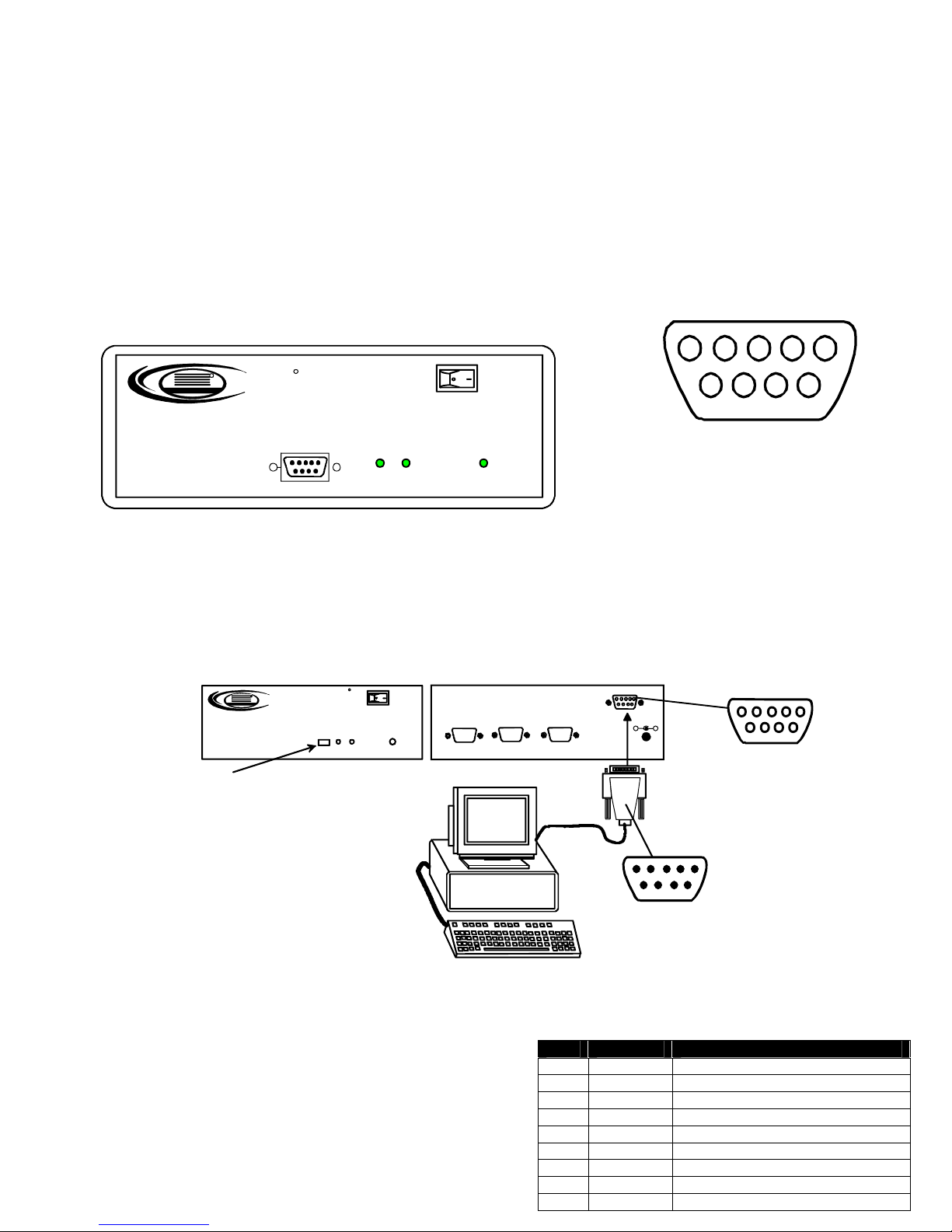
RS232 CONTROL (SE-15V-2U1C-RS Only)
The SE-15V-2U1C-RS can be controlled from the front panel push button (press to switch between MONITOR 1 and MONITOR2)
or it can be controlled using RS232. RS232 control can be achieved using a separate user terminal or CPU with a terminal
program. To make a terminal connection, connect a serial cable (specifications on page 3) between the user terminal and the 9
pin DIN female connector on the VIDMUX labeled "RS232". Configure the terminal program for a baud rate of 9600.
Push button to select
which monitor will
receive video from
CPU
Remote Connection
The RS232 Interface is designed to meet the RS232C standard
and can be controlled from any CPU or other controller with an
RS232 communications port. The pin-out for the 9DB connector
on the unit is as follows:
On the 9DB female connector, pins 1 (DCD), 4 (DTR), and 6
(DSR) are shorted and pins 7 (RTS) and 8 (CTS) are shorted.
Therefore, host handshaking is bypassed and TXD and RXD are
FRONT VIEW OF
SE-15V-2-2U1C-RS
R
NTI
Network Technolo gies I nc
Select
VIDMUX
1
1
2345
1
2 Power
6
Mating Face
8
7
9
of a 9DB Male
REAR VIEW OF
R
VGA
Power
2
SE-15V-2-2U1C-RS
MONITOR 2
VGA
Multi-Scan
Monitor
VIDEO MONITOR 1
RS232
5VDC
2.5A
+
-
9DB male
Serial Connector
Contr ol Te rm in al
RS232 CONNECTOR (9DB FEMALE)
PIN SIGNAL FUNCTION
1 CD Carrier Detect
2 TXD Transmit data (RXD at host)
3 RXD Receive data (TXD at host)
4 DTR Data terminal ready
5 GND Signal ground
6 DSR Data set ready
7 RTS Request to send
2
8 CTS Clear to send
9 - No connection
9DB female
Serial Connector
 Loading...