

NTI SE-15V-xx-L, SE-15V-xx-RS, SE-15V-4-L, SE-15V-8-L, SE-15V-16-L Installation And Operation Manual
...Page 1
V
NTI
NETWORK
R
TECHNOLOGIES
INCORPORATED
1275 Danner Dr
Aurora, OH 44202
www.networktechinc.com
Tel:330-562-7070
Fax:330-562-1999
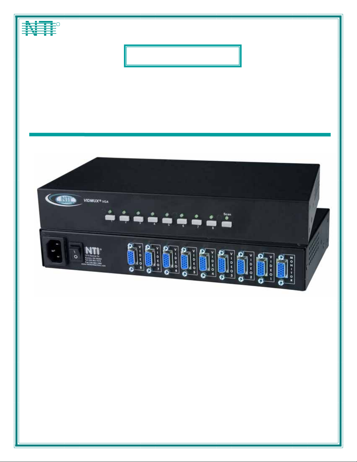
IDMUX®Series
SE-15V-xx-L/RS
4, 8, or 16 Port VGA Video-Only Switch
Installation and Operation Manual
MAN004 Rev Date 2/26/2007
Page 2

TRADEMARK
VIDMUX is a registered trademark of Network Technologies Inc in the U.S. and other countries.
COPYRIGHT
Copyright © 1998-2007 by Network Technologies Inc. All rights reserved. No part of this publication may be reproduced, stored
in a retrieval system, or transmitted, in any form or by any means, electronic, mechanical, photocopying, recording, or otherwise,
without the prior written consent of Network Technologies Inc, 1275 Danner Drive, Aurora, Ohio 44202.
CHANGES
The material in this guide is for information only and is subject to change without notice. Network Technologies Inc reserves the
right to make changes in the product design without reservation and without notification to its users.
i
MAN004 Rev Date 2/26/2007
Page 3

TABLE OF CONTENTS
Introduction....................................................................................................................................................................1
Materials ......................................................................................................................................................................1
Features and Functions................................................................................................................................................2
Rack-Mounting ..............................................................................................................................................................3
To Mount to a Rack .....................................................................................................................................................3
Installation......................................................................................................................................................................4
Cable Connections ......................................................................................................................................................4
RS232 Control ..........................................................................................................................................................4
Power Up Sequence....................................................................................................................................................4
Local Control .................................................................................................................................................................5
Scan Mode................................................................................................................................................................5
RS232 Control................................................................................................................................................................5
RS232 Connections and Configuration.......................................................................................................................5
Remote Connection..................................................................................................................................................5
Baud Rate.................................................................................................................................................................6
Unit Address .............................................................................................................................................................6
Loop Back Dipswitch ................................................................................................................................................6
Command Protocol......................................................................................................................................................8
Autostatus.................................................................................................................................................................9
Scan Mode................................................................................................................................................................9
Matrix Switcher's Control Program For Windows 9X, NT, 2000 AND XP...................................................................9
SerTest- RS232 Interface Test Program...................................................................................................................10
Main Options...........................................................................................................................................................10
Matrix Operations....................................................................................................................................................10
Setup Options.........................................................................................................................................................10
Specifications For Straight-Through RS232 Serial Cable.......................................................................................11
Technical Specifications ............................................................................................................................................11
Troubleshooting..........................................................................................................................................................11
Index.............................................................................................................................................................................12
Warranty Information..................................................................................................................................................12
TABLE OF FIGURES
Figure 1- Make cable connections to the VIDMUX............................................................................................................................4
Figure 2- View of Front of VIDMUX with Local Control......................................................................................................................5
Figure 3- RS232 connection with Matrix-Y-1 cable............................................................................................................................7
Figure 4- Pinout of Matrix-Y-1 cable..................................................................................................................................................7
ii
MAN004 Rev Date 2/26/2007
Page 4

NTI VIDMUX VGA Video-Only Switch
INTRODUCTION
The VIDMUX
plasma screen. VIDMUX Switches are made with either local video connection control with push buttons on the VIDMUX s witch,
or with remote video connection control with an RS232 connection port on the VIDMUX switch.
Models covered by this manual include:
-L = Switches support local video connection control
-RS= Switch supports remote video connection control (RS232)
Features:
®
VGA video switch enables up to 4/8/16 video sources to be connected to a single video monitor, projector or
SE-15V-4-L SE-15V-8-L SE-15V-16-L
SE-15V-4-RS SE-15V-8-RS SE-15V-16-RS
• Compatible with PCs, SUNs and MACs with VGA video.
• Eliminate redundant monitors.
• Ideal for classrooms and boardrooms.
• Interconnect NTI switches & splitters for complex applications.
• Crisp and clear 1900 x 1200 video resolution at 60Hz
Materials
Materials Included with this kit:
¾ NTI SE-15V-4/8/16-L/RS 4,8, or 16 port VGA Video-only Switch
¾ Line cord- country specific
¾ VEXT-3-MM 3 foot 15HD male to 15HD male video cable
¾ 2- Rack-mount ears (4 and 8 port models only)
¾ 6- #6-32x3/16” screws (for attachment of ears on 4 and 8 port models)
¾ 4- rubber feet (4 and 8 port models only)
¾ CD with pdf file of this manual and RS232 Control Software (soft ware only used in models with “-RS”)
1
Page 5

NTI VIDMUX VGA Video-Only Switch
FEA TURES AND FUNCTIONS
R
R
VIDMUX
NTI
Network Technologies Inc
VGA
123456 78
12 3 4 5
1. IEC Cord Connector- for attachment of the country-specific line cord
2. Power switch- used to power the VIDMUX ON/OFF
3. RS232- 9DB female connector- for attachment of a serial cable for RS232 control (only on models ending in “-RS”)
4. Video-x- 15HD female connectors- for connection of video cable from video source(s)
5. Monitor- 15HD female connector- for connection of video cable from user monitor
6. CPU Buttons & LEDs- used to select and indicate connection to desired video source (only on models ending in “-L” )
7. Scan Button & LED- used to toggle Scan mode ON and OFF (only on models ending in “-L” )
8. RS232 Dip switches- for configuring RS232 control connection (only on models ending in “-RS”)
9. Pwr LED- to indicate power has been applied to the VIDMUX (only on models ending in “-RS”)
SE-15V-8-L
(Front View)
5678
R
R
VGA
VIDM UX
NTI
Scan
Network Technologies Inc
SE-15V-8-RS
(Front View)
RS232
On
Off
18
Pwr
67 89
REAR VIEW OF SE-15V-8-RS
R
NTI
1275 Danner Dr
Aurora, OH 44202
Tel:330-562-7070
Fax:330-562-1999
www.ne tworktechinc.com
R
S
2
3
2
V
I
D
E
O
8
V
I
D
E
O
7
V
I
D
E
O
6
V
I
D
E
O
5
V
I
D
E
O
4
V
I
D
E
O
3
V
I
D
E
O
2
V
I
D
E
O
1
M
O
N
I
T
O
R
2
Page 6

NTI VIDMUX VGA Video-Only Switch
RACK-MOUNTING
This NTI switch was designed to be mounted to a rack or to set on a desktop. It includes rackmount ears to make attachment to a
rack easy, and rubber feet to be applied to the bottom of the case if it will instead sit on a flat surface. If this will sit on a flat
surface, simply apply the rubber feet to the bottom of the case in each of the 4 corners.
To Mount to a Rack
1. Attach the ears to the switch using the 6-32x3/16" flat Phillips-head screws (6) provided as shown in the illustration below.
The holes in the ears should line up with pre-threaded holes in the sides of the NTI switch. Tighten the screws securely.
Front of Switch
NTI Switch
6-32x3/16"
Flat Head
Screws
(Provided)
Rackmount Ear
Figure 1- Secure rackmount ears to switch
2. Install 4 captive nuts (not provided) to the rack in locations that line up with the holes in the mounting ear on the NTI switch.
3. Secure the NTI switch to the rack using four screws (typically #10-32 x ¾”- not provided). Each screw should be of sufficient
length to go completely through the NTI mounting ear, rack frame and fully engage all threads in the captive nut. Be sure to
tighten all mounting screws securely.
4. Attach all cables securely to the switch and where necessary supply adequate means of strain relief for cables.
Mounting Screws
(not provided)
NTI Switch
Rack
Captive Nuts
(not provided)
Figure 2- Secure switch to a rack
3
Page 7

NTI VIDMUX VGA Video-Only Switch
INSTALLATION
9DB female
Serial Connector
VGA
Multi-Scan
Monitor
Control Terminal
NTI
1275 Danner Dr
Aurora, OH 442 02
Tel:330-562-7070
Fax:330-562-1999
www.networktechinc.com
REAR VIEW OF SE-15V-8-RS
R
R
S
2
3
2
V
I
D
E
O
8
9DB male
Serial Connector
V
V
I
I
D
D
E
E
O
O
7
6
VEXT-3-MM
(Supplied)
V
V
V
I
I
D
D
E
E
O
O
5
4
V
I
I
D
D
E
E
O
O
3
2
15HD male
CPU
Keyboard Mouse
15HD female
M
V
I
D
E
O
1
Video Connector
O
N
I
T
O
R
Existing cable
VGA
Multi-Scan
Monitor
15HD male
Video Connector
Figure 3- Make cable connections to the VIDMUX
Cable Connections
1. Turn OFF power to video source(s) and monitor(s).
2. Connect the supplied VEXT-3-MM cable between the video port on a video source and th e “VIDEO 1” connector on the
VIDMUX.
3. Connect video cables from additional video sources to the remaining “VIDEO x” ports on the VIDMUX.
FYI: Additional VEXT cables are available from NTI in 1.5,3,6,10,15,25,35,50,75, and 100 foot lengths.
4. Connect VGA monitor to the “MONITOR” connector on the VIDMUX.
5. Connect the IEC power cord to the IEC connector.
RS232 Control
(Applicable to models ending in “-RS” only)
RS232 control can be achieved using a separate user terminal or CPU with a terminal program. To make a terminal connection,
connect a serial cable (specifications on page 11) between the user terminal and the 9 pin DIN female connector on the VIDMUX
labeled "RS232". (See Fig. 3)
Power Up Sequence
1. Power ON the VIDMUX.
2. Power ON the user monitor.
3. Power ON each video source connected.
4
Page 8

NTI VIDMUX VGA Video-Only Switch
LOCAL CONTROL
Note: RS232 Control is not available when the Local Control option is present.
The VIDMUX with model number ending in “-L” is equipped with switches for local control over video connectio ns between the
user and the connected video source. With a video source connected to a numbered video port on the rear of the VIDMUX,
simply press the button associated with the video source to view the video from that video source on the user’s monitor. As long
as the VIDMUX is not in Scan Mode (below), the user will remain connected until another button in pressed.
NTI
Network Technologies Inc
R
VIDMUX
Scan Mode
Models with Local Control also have the feature Scan Mode. When in Scan Mode the VIDMUX scans to each port with a video
source powered-ON. (The SCAN LED on the front panel will illuminate and remain ON while in Scan Mode.) To enter Scan Mode
press the “Scan” button on the front of the VIDMUX. The video from the source will be visible until the VIDMUX switches to the
next powered-ON video source port (5 seconds). To exit Scan Mode, press the “Scan” button again.
R
VGA
12345678
5678
Figure 4- View of Front of VIDMUX with Local Control
Scan
RS232 CONTROL
Note: Local Control is not available when the RS232 Control option is present.
RS232 Connections and Configuration
Models ending in “-RS” include a 9DB female serial connector on the rear of the switch for connection to a terminal or device with
a terminal program. Using a cable wired straight-through (not “null modem” –see specs on page 11), connect a terminal to the
VIDMUX and configure the terminal program. Configure the terminal program and VIDMUX for a b aud rate between 300 and
9600 as instructed below.
Remote Connection
The RS232 Interface is designed to meet the RS232C standard and can be controlled from any CPU or other contro ller with an
RS232 communications port. The pin-out for the 9DB connector on the unit is as follows:
On the 9DB female connector, pins 1 (DCD), 4 (DTR), and 6
(DSR) are shorted and pins 7 (RTS) and 8 (CTS) are shorted.
Therefore, host handshaking is bypassed and TXD and RXD
are the only active signals. A straight-through 9DB serial cable
(not null modem- see specifications on page 11) wil l wo r k
for most CPUs. To daisy chain multiple units, a Matrix Y-1
cable is used (see page 7) for each VIDMUX in the chain.
RS232 CONNECTOR (9DB FEMALE)
PIN SIGNAL FUNCTION
1 CD Carrier Detect
2 TXD Transmit data (RXD at host)
3 RXD Receive data (TXD at host)
4 DTR Data terminal ready
5 GND Signal ground
6 DSR Data set ready
7 RTS Request to send
8 CTS Clear to send
9 - No connection
5
Page 9

NTI VIDMUX VGA Video-Only Switch
Baud Rate
The baud rate can be changed either using the RS232 Command Protocol (page 8) or by powering down the unit, changing the 8
position RS232 dip switch on the front of the VIDMUX, and then powering back up. The table below shows how to set the baud
rate. The default positions are 2,3 and 4 ON as shown in gray.)
Note: The baud rate as configured by the dip switches will be the set baud rate each time the VIDMUX is power cycled,
regardless of what the baud rate is changed to via the RS232 Command Protocol.
DIP SWITCH BAUD RATE
4 3 2
OFF OFF OFF 300
OFF OFF ON 600
OFF ON OFF 1200
OFF ON ON 2400
OFF OFF OFF 4800
ON OFF ON
ON ON OFF
ON ON ON
9600
(default)
On
Off
RS232
18
Unit Address
To allow multiple units to be controlled from a single CPU port, the RS232 control interface is designed to allo w "daisy chaining"
up to 15 units. By setting the appropriate RS232 dip switches, each unit can be given a unique addr ess (1-15). Then the unit will
only respond to commands on the bus if its address is embedded in the command. Use the table below to set the unit address.
The default switch positions are 5 ON, 6 OFF, 7 OFF, and 8 OFF (shown in gray).
DIP SWITCH UNIT ADDRESS
8 7 6 5
OFF OFF OFF OFF
OFF OFF OFF ON 1 (default)
OFF OFF ON OFF 2
OFF OFF ON ON 3
OFF ON OFF OFF 4
OFF ON OFF ON 5
OFF ON ON OFF 6
OFF ON ON ON 7
ON OFF OFF OFF 8
ON OFF OFF ON 9
ON OFF ON OFF 10
ON OFF ON ON 11
ON ON OFF OFF 12
ON ON OFF ON 13
ON ON ON OFF 14
ON ON ON ON 15
0 (not valid)
Loop Back Dipswitch
Dipswitch 1 is the Loop Back dipswitch and should always be set to ON.
On
Off
RS232
18
6
Page 10

NTI VIDMUX VGA Video-Only Switch
Note: In order to connect multiple VIDMUX units together a Matrix-Y-1 cable must be used. (See Fig. 5.) See Fig. 6 for
the pinout of the Matrix-Y-1 cable. The Matrix-Y-1 cable is available from Network Technologies Inc.
CPU
RS232
Serial Port
Matrix-Y-1
Matrix-Y-1 Matrix-Y-1
RS232
NTI
SWITCH
First Unit
RS232
NTI
SWITCH
Second Unit
RS232
NTI
SWITCH
Last Unit
Figure 5- RS232 connection with Matrix-Y-1 cable
Wiring Schematic of Matrix-Y-1 cable
9D Female9D Male 9D Male
(Unit #1)
23
33
555
(Source)
(Unit #2)
Not con nected to
source connector
22
7
Jumper
8
1
4
Jumpers
6
Figure 6- Pinout of Matrix-Y-1 cable
7
Page 11

NTI VIDMUX VGA Video-Only Switch
Command Protocol
CPU controller commands supported by the unit are defined below. All commands should be terminated with a <CR> (carriage
return). All characters in the command string should be upper case, and all numbers below 10 should have a leading 0 (ex: 1 =
01).
Note: Alternatively, the user may use the Matrix Switcher's Control Program or SerTest to control th e VIDMUX via RS232
(see pages 9 and 10).
Legend: (All numbers must be two digits)
SW : Switch (01-15) (Unit Address)
BR : Baud Rate Code (3,6,12,24,48,96)
OP : Output Port (01)
IP : Input Port (01-MAXINPUTS)
<CR> : Carriage Return (Hex 0xD)
Command Definitions
Command
String
CS SW,IP,OP *<CR> Connect One Output Port To Input Port
CA SW,IP *<CR> Connect All Output Ports To Input Port
RO SW,OP *<CR>IP<CR> Read Connection For Output/User Port
CB 00,BR None Change baud rate of serial line
RS SW *<CR> Internal Reset
RV SW,00 *<CR>string\0<CR> Read NTI Version String
RU SW *<CR>IP,OP<CR> Rea d Unit Size
SS SW,00 *<CR> Disable Autostatus feature (see page 9)
SS SW,01 *<CR> Enable Autostatus feature (see page 9)
GO SW,OP *<CR>go SW,OP:IP<CR> Read connection of a Output Port to Input Port
Ss SW,OP,DWT *<CR>
Gs SW,OP *<CR>
Sa SW,OP *<CR> Add al l inputs to scan list of output port
Sc SW,OP *<CR> Remove all inputs from scan list of output port
S+ SW,OP,IP *<CR> Add individual input to Scan List of output por t
S- SW,OP,IP *<CR> Remove individual input from Scan List of output port
Sx SW,OP *<CR>oooxoxxxooooxxx<
SM SW,OP *<CR> Toggle Scan mode
If the syntax of a command is incorrectly entered, the command will be ignored or the switch will answer with a bad response
?<CR>.
Note: The baud rate as changed via RS232 will hold only until the VIDMUX is power cycled. On power-up, th e VIDMUX
will resume the baud rate as configured via the dipswitches on the VIDMUX (see page 6). To make a lasting baud rate
change, adjust the dipswitch positions as indicated in the baud rate chart (page 6).
Good Response Description
BR=03(00),06(00),12(00),24(00),48(00),96(00)
Factory default is 9,600 (see note below)
Set Scan Mode dwell time for specific Output port
DWT values: 000-255 000= scan disabled See page 8 for more info.
Read scan mode dwell time setting for an Output port
DWT<CR>
CR>
DWT values: 000-255 000= scan is disabled for the port
Inspect the Scan List (o=skip x=don't skip)
8
Page 12

NTI VIDMUX VGA Video-Only Switch
Autostatus
When Autostatus is enabled, any output-to-input connection change in the VIDMUX will cause an Autostatus message to be sent
via RS232 to the administrator. The format of the message will be "pc SW,OP:IP<CR>"
Example of an Autostatus message:
pc 01,01:04<CR>
which means "At the switch with unit address 01, the output (01) has changed connection to input 04."
Notes: Any message to the administrator will be delayed by any RS232 traffic being received by the switch from the
administrator.
Autostatus must be disabled before using SerTest or the Matrix Switcher's Control Program (below).
By default, Autostatus is disabled and must be manually enabled. Autostatus is also disabled any time the power to the
VIDMUX is interrupted.
Scan Mode
Scan Mode causes an output port to automatically switch from one input port to the next consecutive input port after a specified
period of time (referred to as the dwell time). Port switching will continue indefinitely and no ports will be skipped, whether there
are video sources connected to them or not. If desired, the VIDMUX can be configured to skip the scanning of specific ports by
removing them from the scan list using the RS232 Command Protocol (page 8).
Dwell time settings can be any value from 0 seconds (000) to 255 seconds. A setting of 000 seconds (the default setting)
disables Scan Mode for that output port. If Scan Mode is disabled for a specific port, then the video to that output will only
change as decided by the administrator.
Matrix Switcher's Control Program For Windows 9X, NT, 2000 AND XP
The Matrix Switcher's Control Program is an easy and powerful graphical program that controls NTI matrix switches through an
RS232 interface. The Matrix Switcher's Control Program is included on the CD packaged with the VIDMUX. The Matrix
Switcher's Control Program is downloaded by clicking on the link "Download Matrix Switcher's Control Program" found on the
web page that appears when you insert the instruction manual CD into your CD ROM drive.
To install the Matrix Switcher's Control Program after downloading
1. Locate the Setup.exe in the directory the program was downloaded to and double-click on it
2. Follow the instructions on the screen
The Matrix Switcher's Control Program performs best on monitors set to a screen resolution of at least 800 X 600. Instruction for
using the Matrix Switcher’s Control Program is available by opening "MSCP Help" in the "NTI" program group once the program
has been installed and is open on the screen.
To open "MSCP Help" from the Windows desktop
1. Click on START
2. Click on PROGRAMS
3. Click on NTI
4. Click on MSCP Help
9
Page 13

NTI VIDMUX VGA Video-Only Switch
SerTest- RS232 Interface Test Program
This software allows a user to test the functions of an NTI server switch, video switch, matrix switch or Multi-user/Multi-platform
switch RS232 interface. The program SERTEST along with the Matrix Switcher's Control Program (page 9) is installed from the
CD packaged with this switch. SERTEST generates a main menu with the 4 selections described below:
Main Options
• Matrix Operations
• Ethernet Operations
• Setup Options
• About SerTest
Matrix Operations
Key Selection Description
1) Connect Video Output/monitor to an Input/Source - connect an output to an input
2) Connect All Video Outputs/monitors to an
Input/source
3) Connect Audio Output/User to an Input/CPU - connect an output to an input (audio ports only)
4) Connect All Audio Outputs/Users to an Input - connect all outputs to an input (audio ports only)
5) Change Mute Status for Audio Output/User (not
applicable to this unit)
6) Change Volume for Audio Output/User (not
applicable to this unit)
7) Read Connection for Video Output/Monitor -read the connection of a specific video output
8) Read Connection for Audio Output/User -read the connection of a specific audio output
9) Read Mute and Volume for Audio Output/User - read the volume and the mute status of the specified audio output
a) Save I/O Connections into Unit Memory -save the connections into switch memory bank
b) Restore I/O Connections from Unit Memory -restore the connections from switch memory bank
c) Change All Uni ts Baud Rate (9600/COM1:) -change RS-232 Baud rate of all switches
d) Reset Unit - send a reset command to the switch
e) Reset All Units - send an internal reset command to all switches
f) Read Unit Size - read the switch size (number of inputs and outputs)
g) Read Unit Version/Revision String -read a string containing the switch version, type, and size
h) Save All Units I/O Connections into Units Memory -save the connections into switch memory bank, command for all
i) Restore All Units I/O Connections from Units
Memory
Selections in the "Key" column that are gray are not applicable to this product.
- send commands to the VIDMUX.
- set Ethernet connection variables (not applicable to VIDMUX)
- set COM port, baud rate, and unit address
- display the program version
- connect all outputs to an input
- mute or un-mute the Audio port output
- change Audio port output volume
-the current baud rate and serial port are displayed in parentheses
- the current unit address is displayed in parentheses
switches
-restore the connections from switch memory bank, command for all
switches
Setup Options
Key Selection Description
1) select Com port current:
(COM1:)
2) select Baud rate current:
(9600)
3) set unit Address current:
(1)
For any selection that requires user input, the user is prompted. When commands are sent to the VIDMUX, the command string
and VIDMUX responses are echoed to the screen. All commands generated by the program are formatted according to the
information provided in sections above. If any transmission problems are detected, an error message is displayed.
Press <Esc> or <Enter> to back out to the main menu and press again to exit.
- select PC serial port
- the current PC serial port is displayed in parentheses
- select PC serial port baud rate
- the current baud rate is displayed in parentheses
- select the unit address
- the current address is displayed in parentheses
10
Page 14

NTI VIDMUX VGA Video-Only Switch
SPECIFICATIONS FOR STRAIGHT-THROUGH RS232 SERIAL CABLE
VIDMUX to PS2 CPU (9 PIN)
VIDMUX PS/2 CPU
9 pin Signal 9 pin
Function Pin # Direction Pin # Function
RxD 3 3 TxD
TxD 2 2 RxD
CTS 7 7 RTS
RTS 8 8 CTS
DSR 4 4 DTR
DTR 6 6 DSR
SG 5 5 SG
Terminals 7 and 8 are jumpered together and terminals 4 and 6 are jump ered together.
1
6
Mating Face
of a 9DB Male
23
7
4
5
8
9
TECHNICAL SPECIFICATIONS
Video resolution 1900x1200 @ 60Hz
Video Bandwidth 230 MHz
Video connectors 15HD female connectors
RS232 connector (“-RS”
models only)
Power 120VAC or 240VAC @ 50 or 60 Hz
Size (In.) WxDxH
(4 & 8 port model)
Size (In.) WxDxH
16 port desktop model
16 port rackmount
9DB female connector
11 x 6 x 1.75
11 x 6 x 3.5
19 x 6 x 1.75
TROUBLESHOOTING
Each and every piece of every product produced by Network Technologies Inc is 100% tested to exacting specifications. We
make every effort to insure trouble-free installation and operation of our products. If problems are experienced while installing this
product, please look over the troubleshooting chart below to see if perhaps we can answer any qu estions that arise. If the
answer is not found in the chart, please check the FAQs (Frequently Asked Questions) at our website at
http://www.networktechinc.com or contact us directly for help at 1-800-742-8324 (800-RGB-TECH) in US & Canada or 1-330-5627070 worldwide. We will be happy to assist in any way we can.
Problem Cause Solution
Video Error Poor cable connection Check cable connections on video source and switch.
Video changes ports
automatically
No RS232 communications
No response to RS232
commands
Unit is in Scan Mode Press Scan Mode button on VIDMUX front panel. Scan
Mode LED should now be OFF
• Baud rate not correct
• Wrong cable used
Improper protocol Verify command string is as described on page 8. Try using
• Verify VIDMUX and terminal are set to same baud rate
Set DIP switches 2,3,4 to ON for 9600.
• Use straight-thru cable (see page 4)
NTI Matrix Switcher’s Control Program (page 9)
11
Page 15

NTI VIDMUX VGA Video-Only Switch
INDEX
Autostatus, 9
baud rate, 6
cable connections, 4
Matrix Switcher's Control Program, 9
Rackmount ears, 3
RS232 cable, 5, 11
RS232 Commands, 8
RS232 connection, 4
RS232 Control, 5
Scan Mode, 5, 9
SerTest, 10
Troubleshooting, 11
unit address, 6
WARRANTY INFORMATION
The warranty period on this product (parts and labor) is two (2) years from the date of purchase. Please contact Network
Technologies Inc at (800) 742-8324 (800-RGB-TECH) or (330) 562-7070 or visit our website at http://www.networktechinc.com
for information regarding repairs and/or returns. A return authorization number is required for all repairs/returns.
PRODUCT
SERIAL NO.:
DATE: INSPECTED BY:
MAN004 Rev. 2/26/07
12
 Loading...