

Page 1
V 1.1 / June 05 / MBe
Less noise More sound•
RT-OS LP
Low-Power Output Switcher
User Manual
V1.1
NTI Headquarters
Im alten Riet 102, 9494 Schaan
Liechtenstein / Europe
Phone: +423 – 239 6060, Fax: +423 – 239 6089
info@nt-instruments.com, www.nt-instruments.com
Page 2
RT-OS LP User Manual
1 DESCRIPTION
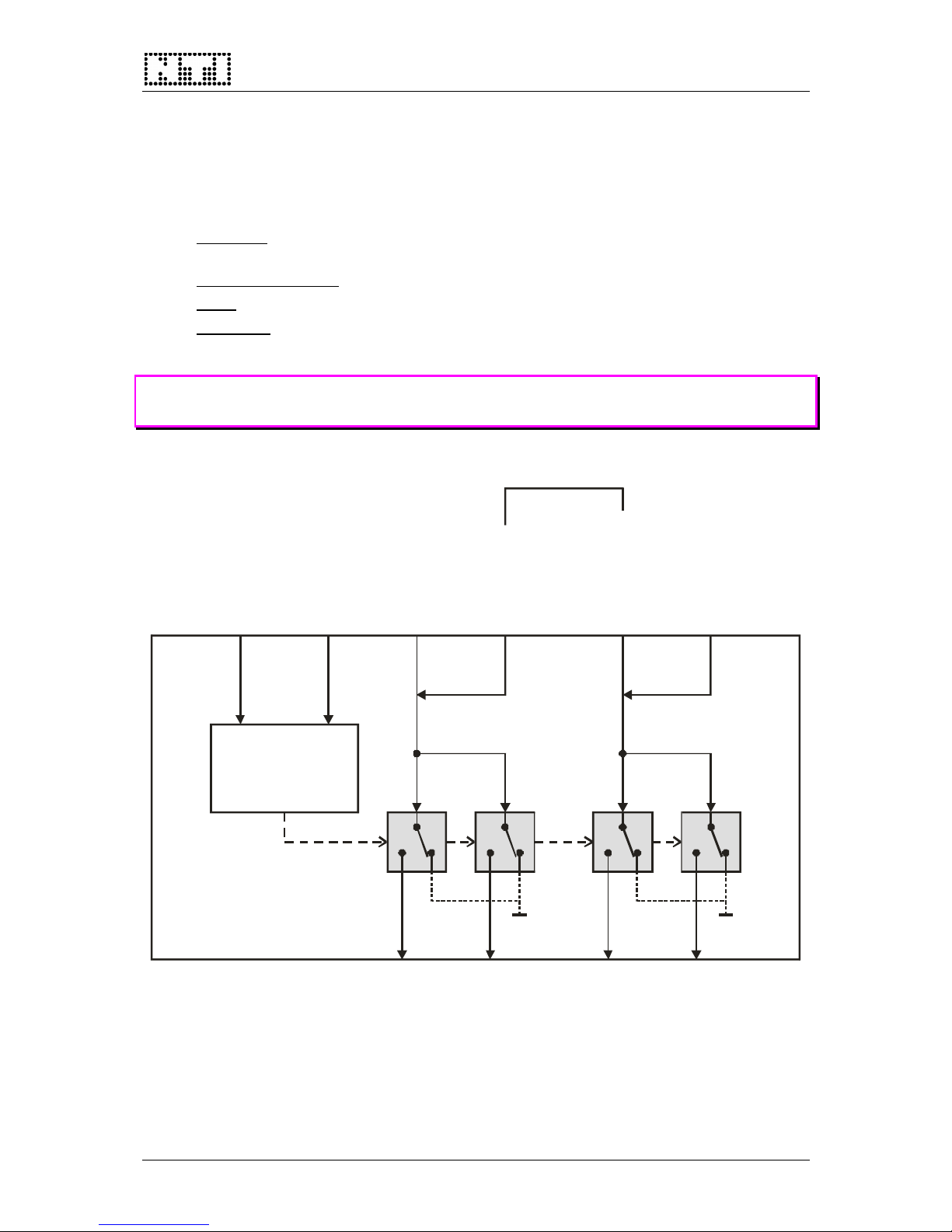
NTI’s RT-OS LP is a low-power output switcher that is controlled from a PC through an USB
link. The switcher comprises two (2) balanced XLR inputs and four (4) XLR outputs that are
normally used as a two-channel 1:2 matrix. Alternatively, the RT-OS LP can also be operated
as a single-channel 1:4 matrix.
•
Device ID: define the individual device ID of the RT-OS LP via the DIP-switch on the
rear panel (chapter
2.3). Up to four RT-OS LP units can be controlled from one PC.
•
1:4 matrix operation: connect INPUT B (or A) externally to IN LINK A (or B).
•
LEDs: the four LEDs on the front panel indicate the active outputs (active ON).
• GND LIFT: these switches allow disconnecting the audio ground (Pin 1 of XLR) of the
corresponding output connectors.
NOTE The RT-OS LP must only be used as an output switcher, whereby the input
current must not exceed 80 mA.
USB Addr ess
(Dip-switch)
USB Cable
USB
Interface
Input A (XLR)
Output A1
(XLR)
Output B1
(XLR)
Output A2
(XLR)
Output B2
(XLR)
Input Link A
(XLR)
Input Link B
(XLR)
Input B (XLR)
InputLink -> 1:4 matri
x
*) wiring of opti o n A
*) *) * ) *)
GND GND
Fig 1 RT-OS LP block diagram
p. 2/6
Page 3

RT-OS LP User Manual
2 INSTALLATION
2.1 Wiring
RT-OS LP is normally used in combination with a PC-software from NTI (i.e. RT-Speaker,
RT-ATS or RT-Compliance). The wiring details are shown in the User Manuals of the
corresponding packages.
NOTE Operate the RT-OS LP Output Switcher only under control of a PC-software
from NTI to avoid damages of peripheral devices or the whole system.
2.2 USB Driver Software
Step 1
Connect the RT-OS LP via an USB cable to the controller PC. As soon as you do this for the
first time, the following message appears:
Fig 2 Installer screen #1
Select the entry “Install from a list or specific
location …” and click in “Next”.
Step 2
Insert the CD-ROM with the control software to your controller PC.
Fig 3 Installer screen #2
On the second installation panel, select the
entry “Search for the best driver in these
locations”, tick the box “Search removable
media …” and click on “Next”.
p. 3/6
Page 4

RT-OS LP User Manual
Step 3
As soon as the installer has found the USB driver on the CD-ROM, the following message
shows up:
Fig 4 Installer screen #3
Click on “Next” to confirm the installation.
Step 4
Fig 5 Installer screen #4
As soon as the driver has been installed
successfully, click on “Finish”.
2.3 Device Address Selection
The DIP-switch on the RT-OS LP rear panel defines the individual
address of the unit. Since the switch can be adjusted in four different
states (“0“, “1“, “2“ or “3“), it is possible to connect & control up to four
RT-OS LP units by one PC.
0
1
2 1
Device ID
Fig 6 DIP-Switch
Example
The DIP-switch settings shown in Fig 6 represent the device address
“1” (= 0*2 + 1*1).
p. 4/6
Page 5

RT-OS LP User Manual
p. 5/6
3 SPECIFICATIONS
3.1 Accessories
• USB cable (included)
• XLR cable (included)
3.2 Audio Inputs
Connectors: XLR female
No. of inputs: 2
Max. input voltage: 50 Vpeak
Max. input current: 80 mA
Bandwidth: DC to 20 kHz
3.3 Audio Outputs
Connectors: XLR male (OUTPUT A, B)
XLR female (OUT LINK A, B)
No. of outputs: 2+2 (each with a ground lift switch)
Bandwidth: DC to 20 kHz
3.4 USB Interface
Connector: USB B type
USB address: 4 addresses (0–3), defined by DIP-switch setting
3.5 General
Switch ON/OFF time: < 2 ms
Temperature, humidity: 0° to 45° C (40 to 110 F)
R.H. < 90% non-condensing
Dimensions: 19” rack device, 1 rack unit high
Page 6

RT-OS LP User Manual
4 APPENDIX – WIRING OF RT-OS LP
4.1 Standard version (XLR pins 2, 3 of inactive outputs are left open)
IN LINK A
INPUT A
OUTPUT A 2 OUTPUT A1
USB
IN LINK B
INPUT B
OUTPUT B2 OUTPUT B1
LIFTLIFTLIFTLIFT GNDGNDGNDGND
21 2 21 2 22
33 3 33 3 33
12 1 12 1 11
4.2 Option A (XLR pins of inactive outputs are shorted)
USB
IN LINK B IN LINK A
INPUT B INPUT A
OUTPUT B2 OUTPUT A2OUTPUT B1 OUTPUT A1
LIFT LIFTLIFT LIFTGND GNDGND GND
2 21 12 22 2
3 33 33 33 3
1 12 21 11 1
p. 6/6
 Loading...