

NTI RACKMUX-V17-N-8/4USBHDU-IP, RACKMUX-V17-N-8USBHDU-IP, RACKMUX-V17-N-8/4USBHDU, RACKMUX-V17-N-8USBHDU, RACKMUX-V17-N-4USBHDU Installation Manual
...Page 1
R
RACKMUX
®
Series
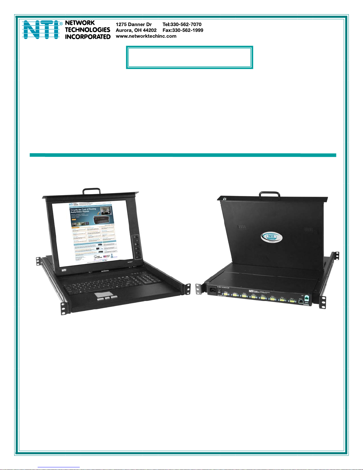
RACKMUX-V17-N-8/4USBHDU(-IP)
Rackmount KVM Drawer with Built-In
High Density USB KVM Switch and KVM on IP™
Installation Manual
MAN129 Rev Date 7/2/2014
ACKMUX-V17-N-8USBHD-IP
(Front and Rear View)
Page 2
TRADEMARK
RACKMUX is a registered trademark of Network Technologies Inc in the U.S. and other countries.
COPYRIGHT
Copyright © 2011, 2014 by Network Technologies Inc. All rights reserved. No part of this publication may be reproduced, stored
in a retrieval system, or transmitted, in any form or by any means, electronic, mechanical, photocopying, recording, or otherwise,
without the prior written consent of Network Technologies Inc, 1275 Danner Drive, Aurora, Ohio 44202.
CHANGES
The material in this guide is for information only and is subject to change without notice. Network Technologies Inc reserves the
right to make changes in the product design without reservation and without notification to its users.
Typographic Conventions
The following table describes the typographic changes used in this instruc t ion.
Typeface
AAaaBBaaCCcc123 On-screen computer output
AAaaBBaaCCcc123
Meaning Example
C:>
What you type, contrasted with on-screen
computer output; keyboard keys to press
C:> L
Press the Fn key
i
Page 3

TABLE OF CONTENTS
Introduction......................................................................................................................................................................1
Materials Included:....................................................................................................................................................1
Materials Not Supplied, but REQUIRED .................................................................................................................1
RACKMUX Single-Person Installation ............................................................................................................................2
Cable Connections..........................................................................................................................................................6
Connect CPUs.............................................................................................................................................................6
Login to USB KVM Switch...........................................................................................................................................7
Password and User Name.....................................................................................................................................7
Connect CAC Card Reader.........................................................................................................................................8
Remote PC Connection...............................................................................................................................................9
Features and Functions.................................................................................................................................................12
Display Functions..........................................................................................................................................................13
Standard Controls......................................................................................................................................................13
OSD Control Menu- 17 Inch VGA models (-V17)......................................................................................................13
OSD Main Menu .....................................................................................................................................................13
Brightness/Contrast Menu......................................................................................................................................14
Color Menu .............................................................................................................................................................14
Position Menu.........................................................................................................................................................14
Setup Menu.............................................................................................................................................................15
Keyboard Functions ......................................................................................................................................................16
Function Key Operation..........................................................................................................................................16
Numeric Keypad Option.............................................................................................................................................17
PS/2-USB Keyboard/Mouse Mode............................................................................................................................18
USING THE UNIMUX USB KVM SWITCH...................................................................................................................19
Basic Operation .........................................................................................................................................................19
OSD Control ..............................................................................................................................................................19
OSD CONTROL............................................................................................................................................................20
Guidelines for Navigating OSD Menus......................................................................................................................20
Security Option..........................................................................................................................................................20
Initial startup ..............................................................................................................................................................21
User Access Functions..............................................................................................................................................21
Command Mode .....................................................................................................................................................21
Settings...................................................................................................................................................................23
OSD Settings..........................................................................................................................................................24
Find Mode...............................................................................................................................................................24
Help Mode...............................................................................................................................................................25
Scan Mode..............................................................................................................................................................25
Broadcast Mode......................................................................................................................................................26
Normal Mode ..........................................................................................................................................................26
Security......................................................................................................................................................................27
Enabling Security....................................................................................................................................................27
Password and User Name...................................................................................................................................27
User Login...............................................................................................................................................................28
Additional OSD Modes Available With Security Enabled..........................................................................................28
Administration Menu...............................................................................................................................................28
System Configuration .............................................................................................................................................29
Port Configuration...................................................................................................................................................29
User Configuration..................................................................................................................................................30
Edit User Account...................................................................................................................................................30
User Access Control...............................................................................................................................................31
Change Administrator Password............................................................................................................................31
Display Usage.........................................................................................................................................................32
Ethernet Configuration............................................................................................................................................32
Idle Timeout............................................................................................................................................................33
OSD Blank Timeout................................................................................................................................................33
ii
Page 4

Alternate Command Hot Key..................................................................................................................................34
Reset Port names...................................................................................................................................................34
Select Keyboard Language ....................................................................................................................................35
Security Configuration ............................................................................................................................................35
Serial Baud Rate.....................................................................................................................................................36
Serial Address.........................................................................................................................................................37
Keyboard Mapping.....................................................................................................................................................38
Key Equivalents.........................................................................................................................................................38
Mouse Click Equivalents............................................................................................................................................38
SUN’s 16 Extra Keys ..............................................................................................................................................38
RS232 CONTROL.........................................................................................................................................................40
Remote Connection................................................................................................................................................40
Baud Rate............................................................................................................................................................40
Unit Address and Loop Back...............................................................................................................................40
RS232 Command Protocol........................................................................................................................................42
RS232 Command Protocol Quick Reference.........................................................................................................42
Autostatus............................................................................................................................................................42
NTI Switch Control Program For Windows 9X, NT, 2000, XP, Vista and 7 ..............................................................43
SerTest- RS232 Interface Test Program...................................................................................................................44
Main Options...........................................................................................................................................................44
Matrix Operations....................................................................................................................................................44
Setup Options.........................................................................................................................................................44
RMTEST-RS232 Interface Test Program..................................................................................................................45
SUN RAY SUPPORT....................................................................................................................................................46
FIRMWARE UPGRADE PROCEDURE........................................................................................................................47
Requirements ............................................................................................................................................................47
Preparation For Upgrade...........................................................................................................................................48
Upgrade Procedures..................................................................................................................................................49
Start the Bootloader................................................................................................................................................49
Update the User Controller Firmware.....................................................................................................................50
Update the HID Port Controller Firmware...............................................................................................................50
Update the Vendor Specific Port Controller Firmware............................................................................................51
Read the Checksum of HID or Vendor Specific Port Controller Firmware.............................................................52
SAFETY.........................................................................................................................................................................53
Rackmux-KVM Drawer Standard Specifications...........................................................................................................54
General Specs...........................................................................................................................................................54
LCD............................................................................................................................................................................54
Display Controller: VGA.............................................................................................................................................54
OSD Control Board....................................................................................................................................................54
Keyboard....................................................................................................................................................................54
Touchpad...................................................................................................................................................................55
Troubleshooting For KVM Drawer.................................................................................................................................56
Index..............................................................................................................................................................................57
Warranty Information.....................................................................................................................................................57
iii
Page 5

TABLE OF FIGURES
Figure 1- Adjustable rail assemblies..................................................................................................................................................2
Figure 2- Install the cage nuts............................................................................................................................................................3
Figure 3- Install the rail assemblies ...................................................................................................................................................3
Figure 4- Check spacing of the rails ..................................................................................................................................................4
Figure 5- Rail guides..........................................................................................................................................................................4
Figure 6- Apply remaining screws to complete installation ................................................................................................................5
Figure 7- Connect each CPU using a HDUSBVEXT-xx-MM cable....................................................................................................6
Figure 8- USB KVM Switch OSD Splash Screen...............................................................................................................................7
Figure 9- User login screen................................................................................................................................................................7
Figure 10- Install CAC card reader ....................................................................................................................................................8
Figure 11- Connect Remote PC to KVM on IP at "LAN" port.............................................................................................................9
Figure 12- Login Screen for KVM on IP.............................................................................................................................................9
Figure 13- Network Configuration screen ........................................................................................................................................10
Figure 14- Remote Console Preview...............................................................................................................................................11
Figure 15- OSD Controls .................................................................................................................................................................13
Figure 16- US(English) Keyboard Layout ........................................................................................................................................16
Figure 17- Keyboard LED Indications..............................................................................................................................................16
Figure 18- U.S. (English) keyboard with numeric keypad................................................................................................................17
Figure 19- U.K. (English) keyboard with numeric keypad................................................................................................................17
Figure 20- German keyboard with numeric keypad .........................................................................................................................18
Figure 21- Command Mode main menu-User..................................................................................................................................22
Figure 22- Administrator’s main menu.............................................................................................................................................23
Figure 23- Settings menu.................................................................................................................................................................23
Figure 24- OSD Settings screen......................................................................................................................................................24
Figure 25- Find Mode in use............................................................................................................................................................24
Figure 26- Main Menu help screen..................................................................................................................................................25
Figure 27- Scan List.........................................................................................................................................................................25
Figure 28- Broadcast List .................................................................................................................................................................26
Figure 29- User login screen............................................................................................................................................................27
Figure 30- Administrator's main menu.............................................................................................................................................27
Figure 31- User Login screen with security disabled .......................................................................................................................28
Figure 32- Administration Mode Menu.............................................................................................................................................28
Figure 33- System Configuration menu ...........................................................................................................................................29
Figure 34- Port Configuration menu.................................................................................................................................................29
Figure 35- User Configuration..........................................................................................................................................................30
Figure 36- User Account menu........................................................................................................................................................30
Figure 37- Access Control list..........................................................................................................................................................31
Figure 38- Administrator password menu...................................................................................................................................31
Figure 39- Usage Statistics Page ....................................................................................................................................................32
Figure 40- Ethernet Configuration....................................................................................................................................................32
Figure 41- Change value of Idle Timeout.........................................................................................................................................33
Figure 42- Change the value of OSD Blank Timeout.......................................................................................................................33
Figure 43- Alternate Command Hot Key selection window..............................................................................................................34
Figure 44- Press "R" to reset port names ........................................................................................................................................34
Figure 45- Select Language menu...................................................................................................................................................35
Figure 46- Security Configuration ....................................................................................................................................................35
Figure 47- Login screen with security disabled................................................................................................................................36
Figure 48- Adjust Baud Rate............................................................................................................................................................36
Figure 49- Adjust Serial Address.....................................................................................................................................................37
Figure 50- Keyboard layouts............................................................................................................................................................39
Figure 51- RS232 connection with Matrix-Y-1 cable........................................................................................................................41
Figure 52- Pinout of Matrix-Y-1 cable ..............................................................................................................................................41
Figure 53- Preparation for firmware upgrade...................................................................................................................................48
iv
Page 6
NTI RACKMUX-V17-N-8USBHD-IP RACKMOUNT DRAWER WITH USB KVM SWITCH AND KVM ON IP
INTRODUCTION
The RACKMUX® KVM Drawer with Built-In High Density USB KVM Switch combines a rackmount LCD monitor, keyboard,
touchpad mouse, a 4, 8 or 16-port USB switch.
Option: Include a KVM on IP device for remote access to the KVM switch and connected PCs- just add “-IP” to part number (i.e.
RACKMUX-V17-N-8USBHD-IP)
Option: USB device port for connection of a CAC card reader- add a “U” to the model number (RACKMUX-V17-N-8USBHDU)
Features Include:
• Available with forward-folding 17" TFT/LCD VGA monitor.
o 1280x1024 video resolution for 17" monitor.
o Tilt LCD up and back to adjust to any comfortable viewing angle to 120°
• Compatible with USB computers.
• Remotely access multiple computers connected to the USB KVM Switch using a standard Internet browser.
• Securely gain BIOS level access to systems for maintenance, support, or failure recovery over the Internet.
• Torque-friction hinges – monitor does not wobble, spring, or slam shut.
• Compact, heavy-duty tactile keyboard with 17-key numeric keypad.
• Drawer locks into place when open to prevent it from sliding in and out of the rack.
o Front quick-release latches for pushing the drawer back into the rack.
• Rugged steel construction with durable powder coat finish.
• LCD auto-shutoff in closed position.
• Optional KVM on IP™ requires no client software. Secure connections can be made with any browser.
Materials Included:
• RACKMUX KVM Drawer
• IEC Power cord- country specific
• Rackmount kit
• DB9 Female-to- RJ45 Female adapter
• DB25 Female-to-RJ45 Female adapter
• 5 foot RJ45-to-RJ45 CAT5 p atch cable
• CAT5-CO-MF Crossover Adapter
• CD with PDF file of this manu al, RS232 control software, and more
Materials Not Supplied, but REQUIRED
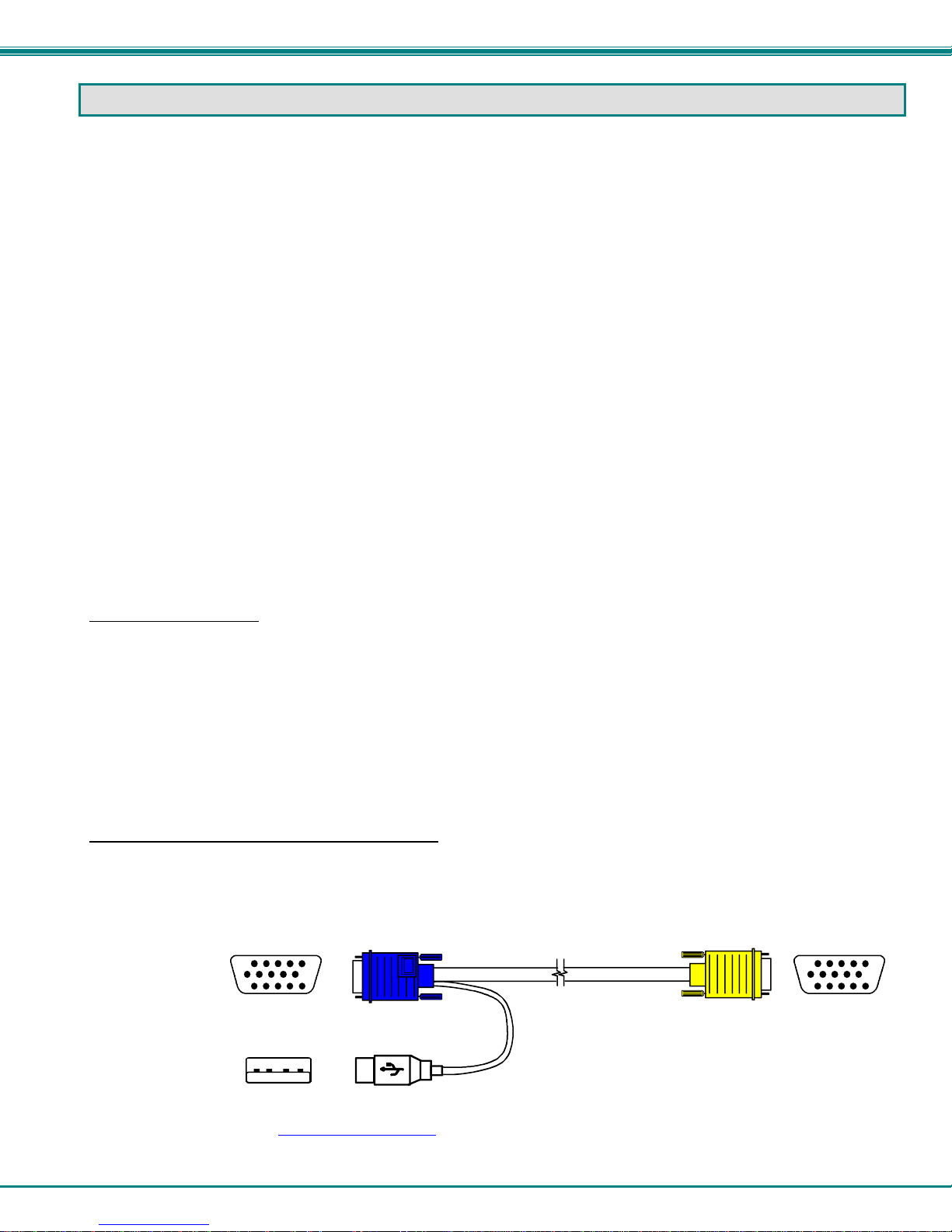
• HDUSBVEXT-xx-MM cable for each CPU being connected to the switch
Where: xx is the length of the cable in feet (3,6,10, or 15 feet available)
MM indicates male-to-male connector
Cables can be purchased from Network Technologies Inc by calling 800-RGB-TECH (800-742-8324) or 330-562-7070
or by visiting our website at www.networktechinc.com
15HD-Male
USB Type A
Male
HD15 Male
Video
USBType A Male
.
HDUSBVEXT-xx-MM
(3,6,10 and 15 foot cables available)
HD15 Male
High Density
15HD-Male
1
Page 7
NTI RACKMUX-V17-N-8USBHD-IP RACKMOUNT DRAWER WITH USB KVM SWITCH AND KVM ON IP
RACKMUX SINGLE-PERSON INSTALLATION
Your NTI RACKMUX Drawer was designed for easy installation by one person with a minimum of tools and effort. Follow the
simple steps below to quickly install your RACKMUX Drawer.
If you would like to see a video of this installation, see the link on the page that opens when you insert the CD that accompanied
your RACKMUX, or open single-person-installation.mp4
1. Locate and unpack the hardware bag. Your hardware bag will include all items n e cessary to install the specific RACKMUX
model (see the manual that accompanied your RACKMUX drawer), including the following hardware unique to the Single-Person
hardware installation:
• 10- #10-32 cage nut
• 2- #10-32 x 1/2” flat-head machine screw
• 8- #10-32 x 3/4” pan-head machine screw
To install the rails you will need only a tape measure and Phillips screwdriver.
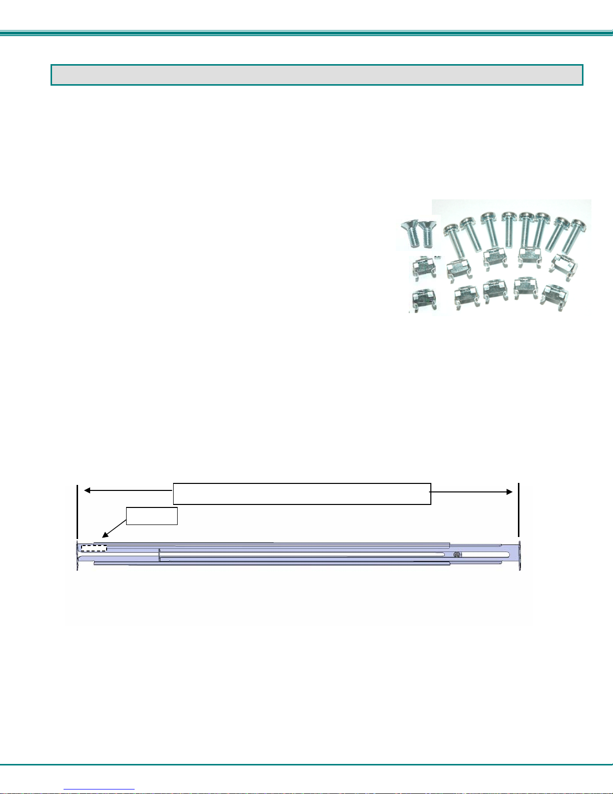
2. Unpack the left and right rail assemblies. Each are labeled “Right Front” and “Left Front” to indicate their intended position and
orientation. Extend each rail assembly to the dimension required for your rack. Rail assemblies are adjustable to fit within a rack
between 24” and 40” in depth.
Labeled
Rail assemblies are adjustable in len gth from 24” to 40”.
on the CD.
Figure 1- Adjustable rail assemblies
2
Page 8
NTI RACKMUX-V17-N-8USBHD-IP RACKMOUNT DRAWER WITH USB KVM SWITCH AND KVM ON IP
R
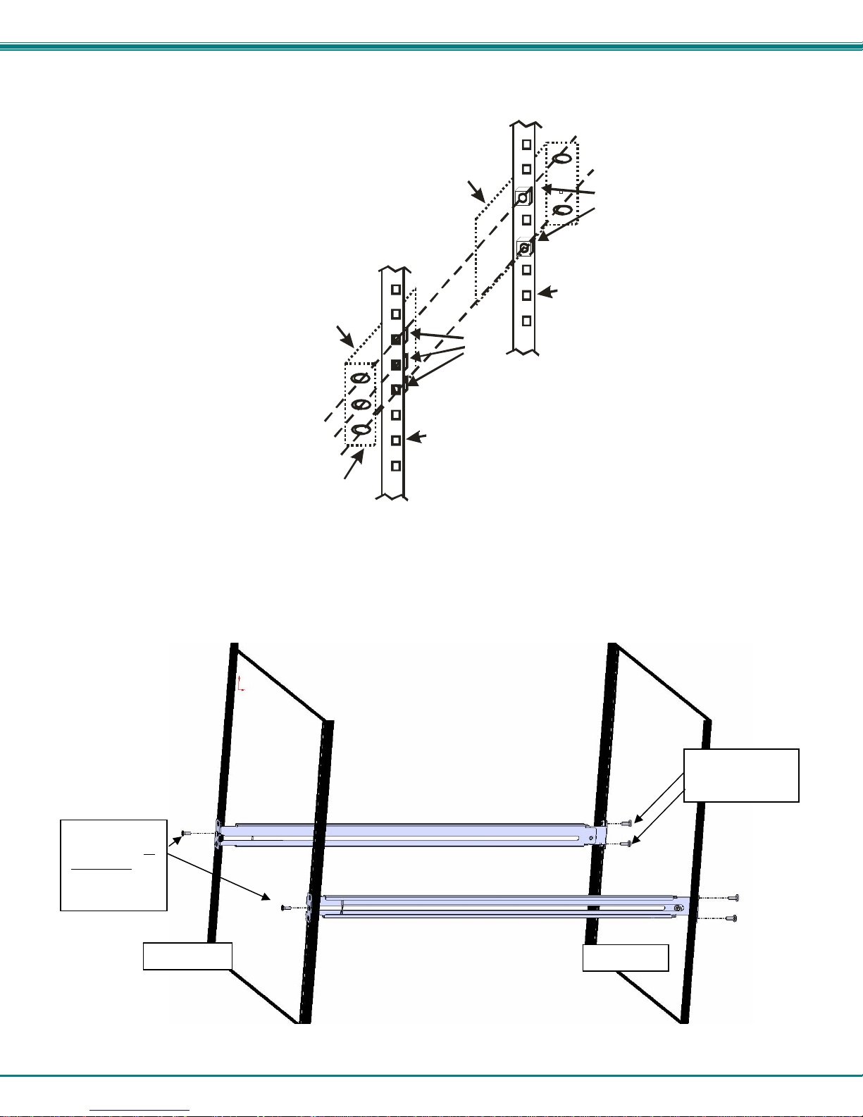
3. Install six #10-32 cage nuts at the front of the rack in positions where the RACKMUX will be mounted (three in each side).
Install four more cage nuts at the rear of the rack in positions straight across from the upper and lower cage nuts installed in front.
Ext ender Rail
Rail Flange
Extender Rail
Cage
Nuts
Rear Rack
Support
Cage
Nuts
Front Rack
Support
Figure 2- Install the cage nuts
4. Install the right rail assembly. The end with the label “Right Front” mounts to the front rack support. Install only the center
screw through the rail flange to the rack support and cage nut using the #10-32 x 1/2” flat head machine screw provided. (See
image below.) Do not tighten at this time. Install the left rail assembly in the same fashion. The end with the label “Left Front”
mounts to the front rack support.
5. Install two #10-32 x 3/4” pan-head screws in the rear of each rail assembly as shown below. Do not tighten at the time.
Install one flat
head screw in
the center in
each side at
the front
Rack Front
ack Rear
Install two
screws in each
Figure 3- Install the rail assemblies
3
Page 9
NTI RACKMUX-V17-N-8USBHD-IP RACKMOUNT DRAWER WITH USB KVM SWITCH AND KVM ON IP
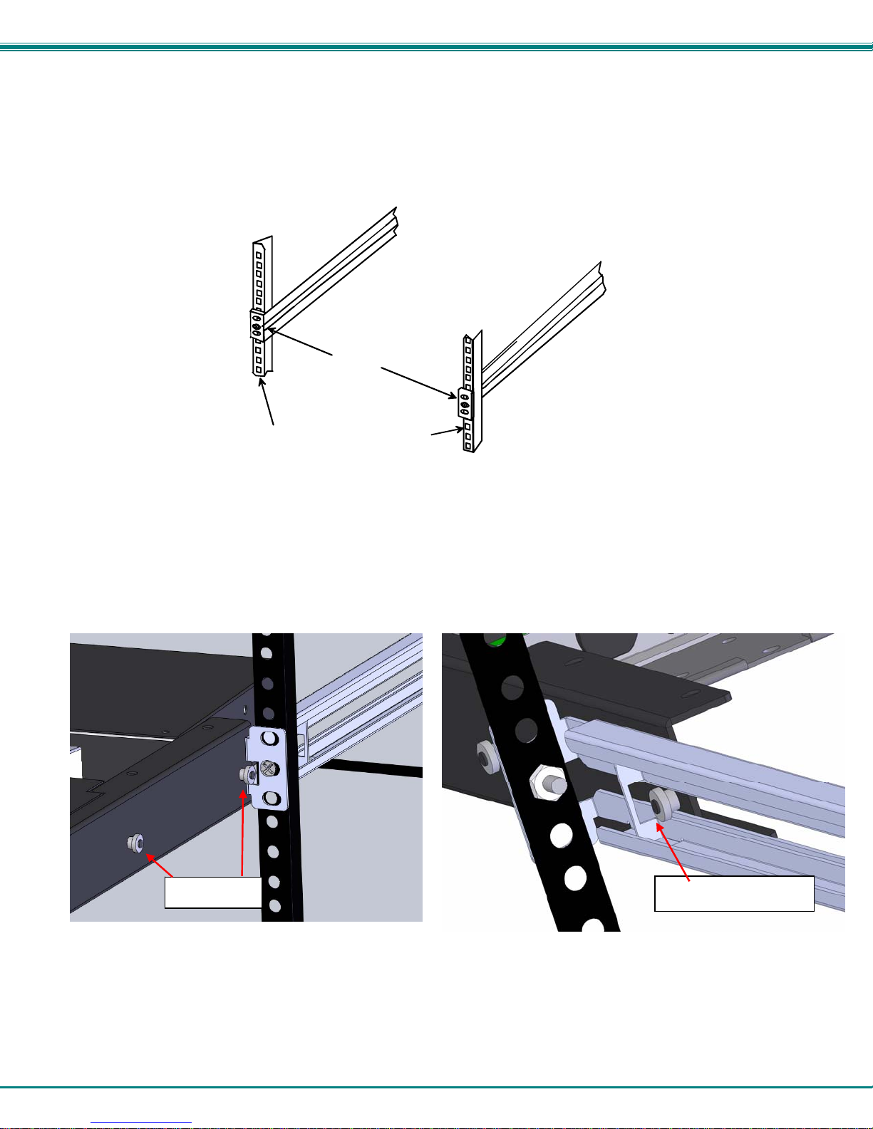
6. Measure the distance between the inside of the rails at the front of the rack. Adjust the distance to 17-1/4” and tighten the flathead screws to the rail flanges securely.
Left Rail
Right Rail
17-1/4"
Front Rack Supports
Figure 4- Check spacing of the rails
7. Lineup the rail guides on the RACKMUX drawer with the slots in the front of the left and right rails and slide the drawer into the
rack. The rail guides should be positioned such that the wide lip of the guide is on the backside of the rail. Slide the drawer i n
completely.
View of rail guide from the front of the rack support View of rail guide from the backside of the rail
Rail guides
Wide lip of rail guide
Figure 5- Rail guides
4
Page 10

NTI RACKMUX-V17-N-8USBHD-IP RACKMOUNT DRAWER WITH USB KVM SWITCH AND KVM ON IP
8. Apply four more #10-32 x 3/4" pan-head machine screws (two for each) through the holes in the drawer flanges, through the
holes in the left and right rails, into the cage nuts in the rack supports. Tighten each securely.
Apply two
more screws
on each side
There should
be a total of
six screws
the front now.
at
Figure 6- Apply remaining screws to complete installation
9. Tighten securely the four screws applied to the rear rail flanges in step 4.
10. Make your cable connections according to your RACKMUX Drawer instructions.
Your NTI RACKMUX Drawer is now installed and ready for use.
5
Page 11
NTI RACKMUX-V17-N-8USBHD-IP RACKMOUNT DRAWER WITH USB KVM SWITCH AND KVM ON IP
CABLE CONNECTIONS
Connect CPUs
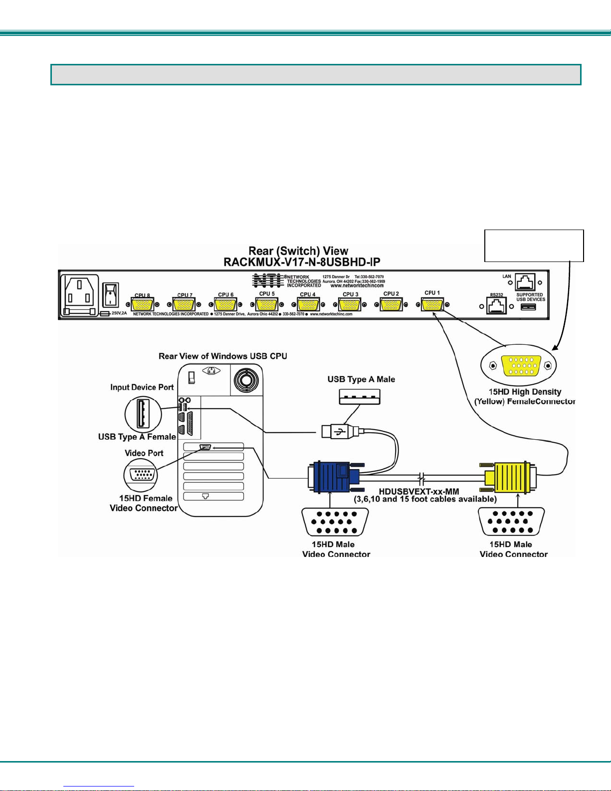
1. For each CPU:
• Connect a USB type A cable end of a HDUSBVEXT-xx-MM cable to a USB type A female user device port on a CPU.
• Connect the 15HD blue male cable end of a HDUSBVEXT-xx-MM cable to the video port of the same CPU.
• Connect the 15HD yellow male cable end of the HDUSBVEXT-xx-MM cable to a yellow “CPU x” port on the USB KVM
switch. (See Figure 7)
Port color may be
black or yellow
Figure 7- Connect each CPU using a HDUSBVEXT-xx-MM cable
2. Power-ON the CPUs.
• The CPUs can be powered at any time although if a CPU needs a keyboard and/or mouse at power-ON it should be
powered after connecting to and powering-ON the RACKMUX.
Note: The order in which the CPUs and switch are powered up does not matter. A power strip can be used.
3. Power-ON the RACKMUX. (The RACKMUX can be powered at any time.)
6
Page 12

NTI RACKMUX-V17-N-8USBHD-IP RACKMOUNT DRAWER WITH USB KVM SWITCH AND KVM ON IP
Login to USB KVM Switch
Immediately after powering ON the RACKMUX, the OSD splash screen shown below will appear on the monitor if the RACKMUX
keyboard is in USB mode (see page 17) :
If the OSD Splash screen does not display, press <
monitor.
If the security option is enabled, when the UNIMUX is powered up the user will be prompted for a username and password to
continue. If the security option is not enabled the monitor will display the desktop image for the connected CPU and the user
can continue with normal operation of the connected CPU.
Press any key to open the Command Mode menu.
Ctrl> + <`> (accent/tilde key). The OSD menu will automatically appear on the
Figure 8- USB KVM Switch OSD Splash Screen
If security is enabled and you are prompted for a name and password, login as the admini strator.
Password and User Name
The factory settings are:
• default user name = <root>
• default password = <nti>
Note: The username for the administrator cannot be changed
from "root”.
After login the Command Mode menu will open and the USB KVM Switch will be ready to configure and use. For more details on
the use of the USB KVM Switch, RS232 Control and more, see man039.pdf entitled “UNIMUX-USBV-xHD High Density USB
KVM Switch Installation and Operation Manual” on the Product Manual CD.
Note: The RS232 connector on the USB KVM switch is connected and used as described in the UNIMUX-USBV-xHD
manual. It is not used as described in the KVM-IP manual that is also included with this product. The RS232 port
referred to in the KVM-IP manual is not accessible and therefore not applicable to this product.
Figure 9- User login screen
7
Page 13
NTI RACKMUX-V17-N-8USBHD-IP RACKMOUNT DRAWER WITH USB KVM SWITCH AND KVM ON IP
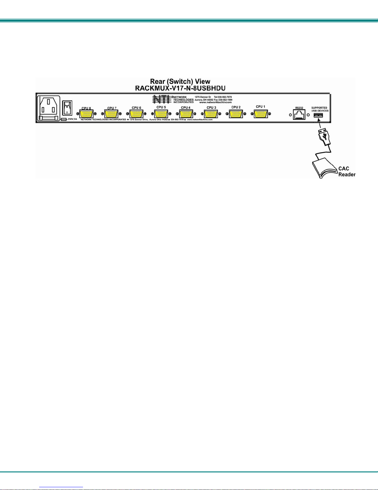
Connect CAC Card Reader
If the RACKMUX you have purchased includes the USB port option (RACKMUX-V17-N-8USBHD
connection of a CAC card reader. When used, the CAC card reader will connect to the PC attached to the selected “CPUx” port.
Figure 10- Install CAC card reader
U), then it supports the
8
Page 14
NTI RACKMUX-V17-N-8USBHD-IP RACKMOUNT DRAWER WITH USB KVM SWITCH AND KVM ON IP
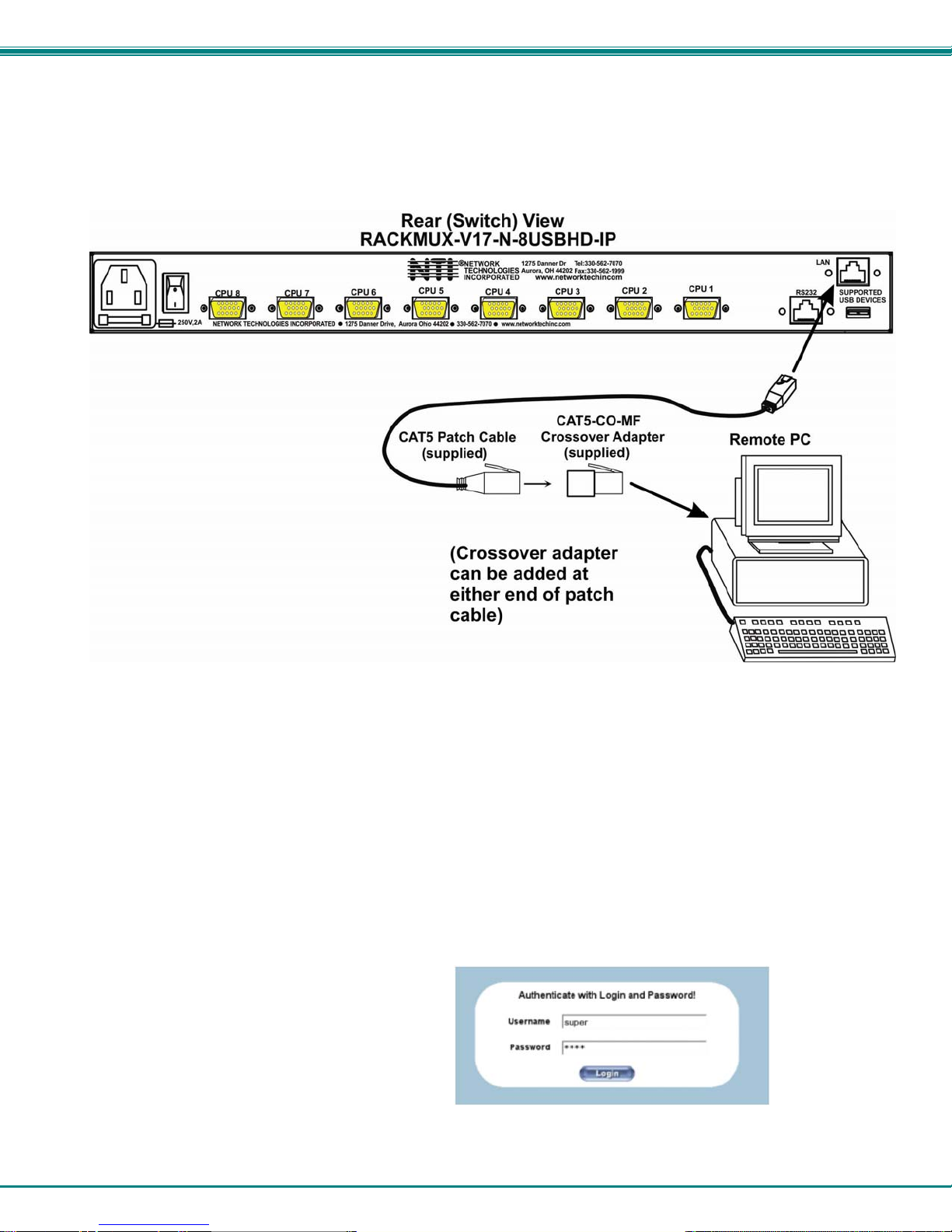
Remote PC Connection
If the KVM on IP option was purchased (RACKMUX-V17-N-8USBHD-IP):
1. Make a connection between an available RJ45 Ethernet port on a PC and the “LAN” port on the RACKMUX switch. A five foot
patch cable and crossover adapter have been included for this purpose.
Figure 11- Connect Remote PC to KVM on IP at "LAN" port
2. The default IP of the KVM on IP is 192.168.0.70. The Ethernet port on the PC must be configured with an IP of 192.168.0.xxx
where xxx is any number except 70. You may need to configure the Ethernet port network information on the PC such that it can
connect to the KVM on IP device in the USB KVM switch
Note: Connecting to the KVM on IP requires the installation of the Java Runtime Environment. A link to the web page
from which it can be downloaded and installed in addition to a Windows compatible copy of the application is provided
on the Product Manual CD.
3. Open a browser window on the PC. Type “192.168.0.70” into the URL address block. A login prompt will appear.
4. Enter the default user name and password for the KVM on IP:
Username = super
Password = pass
Figure 12- Login Screen for KVM on IP
9
Page 15
NTI RACKMUX-V17-N-8USBHD-IP RACKMOUNT DRAWER WITH USB KVM SWITCH AND KVM ON IP
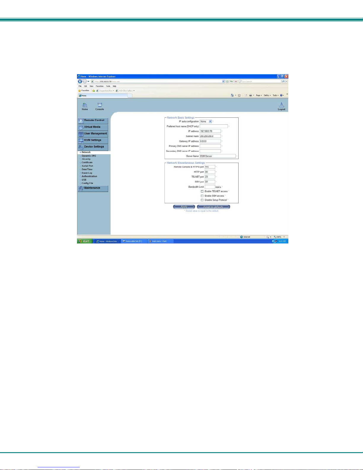
5. The KVM on IP will open the main menu. If you wish to change the network configuration, go to “Device Settings”, and then
“Network” to open the network configuration settings page for the KVM on IP. If you don’t need to change the n etwork settings,
skip directly to step 10.
Figure 13- Network Configuration screen
6. Enter the desired network connection settings (IP address, subnet mask, gateway) as compatible with your network.
Make note of these settings in case you need them later.
7. With the settings updated, press “Apply” to implement the changes in the KVM on IP. Your browser connection to the KVM
on IP is no longer valid.
8. To restore connection to the KVM on IP, change the IP address on the PC back to an address compatible with your network
and now also compatible with the KVM on IP.
Having configured the KVM on IP to be compatible with your network, you can now make a direct cable connection (crossover
adapter not needed) to your network through a router or switch.
9. Enter the new IP address in the browser URL address block. Log back into the KVM on IP.
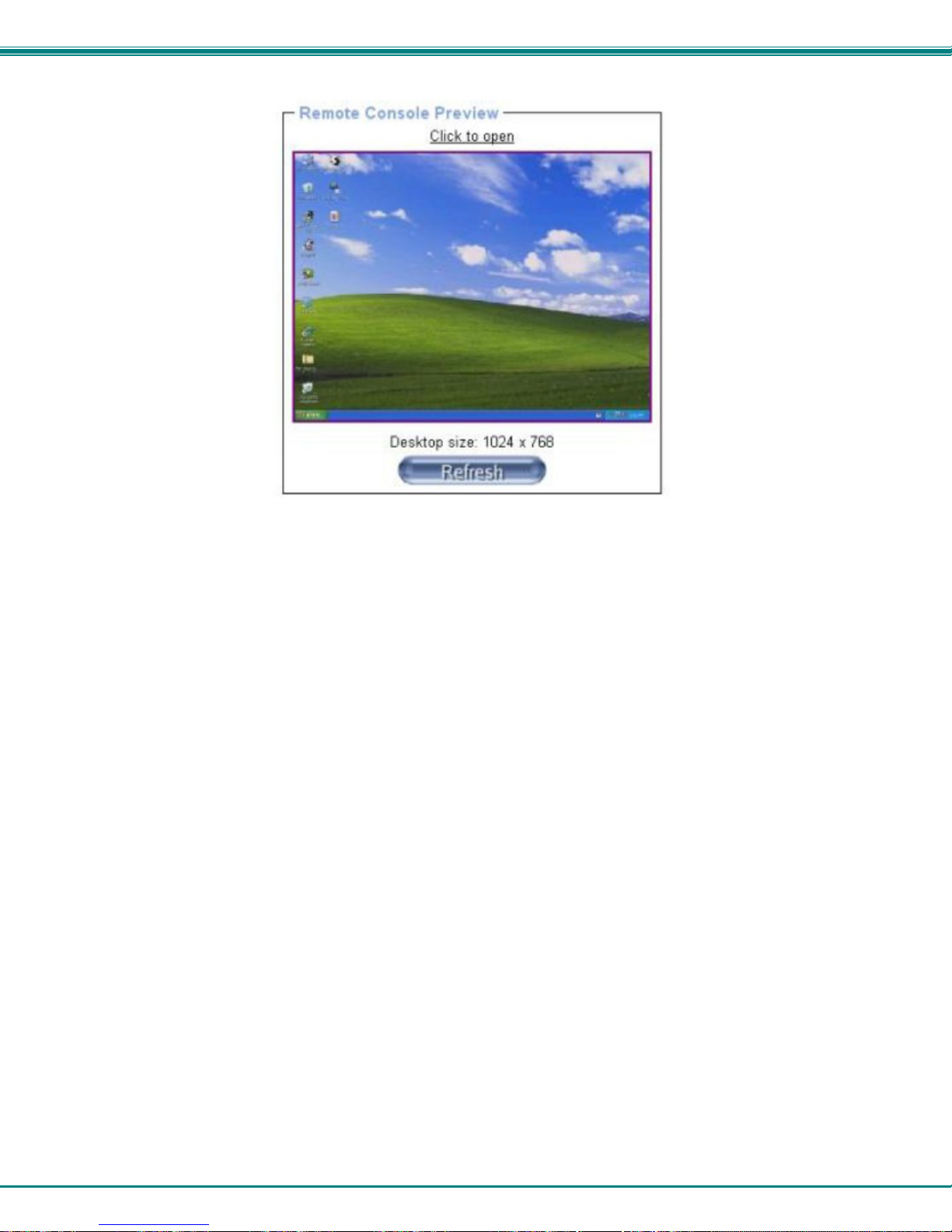
10. With a proper login, a window “
Remote Console Preview” will be displayed. Click on the link “Click to open”.
10
Page 16
NTI RACKMUX-V17-N-8USBHD-IP RACKMOUNT DRAWER WITH USB KVM SWITCH AND KVM ON IP
Figure 14- Remote Console Preview
A connection will be made between your remote PC and the RACKMUX Drawer. The screen that opens is a virtual PC that
enables you to control the RACKMUX switch just as if you were actually at the keyboard of the RACKMUX. Using the mouse,
switch between the virtual PC and your actual computer interface.
Instruction for operating the USB KVM Switch can be found on page 19.
Note: When using the OSD menu to control the USB KVM switch from the remote PC, use only the keyboard to navigate
the menus. The mouse will work as described in the UNIMUX-USBV-xHD manual when used from the RACKMUX-based
keyboard, but it is not reliable when used through the KVM on IP connection.
If the remote connection is closed while in the KVM on IP menu, to re-open the connection click on “
KVM Console”.
“
Note: There are more features available in the menu for the KVM on IP, but their use or configuratio n is not necessary in
the operation of the RACKMUX-V17-N-8USBHD-IP.
Remote Control”, then
11
Page 17
NTI RACKMUX-V17-N-8USBHD-IP RACKMOUNT DRAWER WITH USB KVM SWITCH AND KVM ON IP
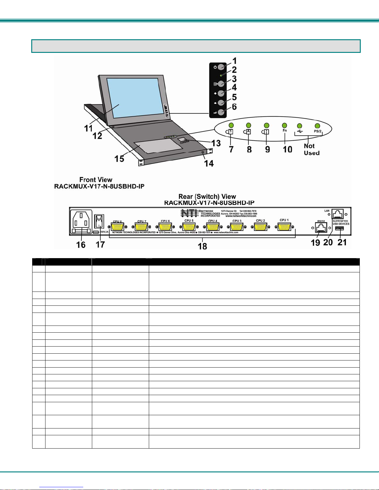
FEATURES AND FUNCTIONS
#
LABEL PHYSICAL DESCRIPTION
1 Power
--- Green/Red LED Indicates operation status
2
Menu
3
Up Arrow
4
Down Arrow
5
Select
6
NumLock
7
CapsLock
8
Scroll Lock
9
Fn
10
--- LCD Display for viewing the video signal from the connected CPU
11
--- Auto Shut-OFF switch automatically shuts OFF the LCD display when the monitor is folded down
12
--- 3-button mouse for controlling mouse movements on the monitor and controlling the computer
13
--- Keylock to prevent unauthorized use of the RACKMUX
14
--- Keyboard for manual data entry and computer control
15
--- IEC Connector for attachment of the IEC power cord to power the RACKMUX drawer
16
--- Switch for powering ON and OFF the RACKMUX drawer
17
18 CPU x
19 RS232
LAN
20
USB Port
21
More information on the use of the USB KVM Switch features can be found on the manual CD in man039.pdf entitled “UNIMUXUSBV-xHD High Density USB KVM Switch Installation and Operation Manual”
Button press to turn the LCD monitor ON and OFF
Green = Power-ON, Video Input Signal OK
Red = Suspend / Stand-by, or no Video Input Signal
Button press to turn ON the OSD menu
Button press to move the cursor in the OSD menu up
Button press to move the cursor in the OSD menu down
Button press to select a menu item (when OSD menu is ON) or press to auto adjust the
video quality (when OSD menu is OFF)
Green LED illuminates when the number lock is ON
Green LED illuminates when CapsLock is ON
Green LED illuminates when the Scroll Lock keyboard feature is ON.
Green LED illuminates when Function Features (page 13) are enabled
15HD yellow female
high-density
RJ45 female for attaching RS232 interface cable from a CPU to control the functions of one or
RJ45 female (OPTIONAL) for connection to an Ethernet for remote user control via KVM on IP
USB Type A female
for connection of CPU cables for video and device support
more switches
(OPTIONAL) for USB cable of a CAC card reader
12
Page 18
NTI RACKMUX-V17-N-8USBHD-IP RACKMOUNT DRAWER WITH USB KVM SWITCH AND KVM ON IP
DISPLAY FUNCTIONS
An NTI RACKMUX with a 17” monitor supports resolutions up to 1280 x 1024, and a 20” monitor supports resolutions up to 1600 x
1200, each with a refresh rate at between 55 and 76Hz. The quality of the image on the LCD monitor is adjustable using an On
Screen Display (OSD) menu using the control buttons on the RACKMUX.
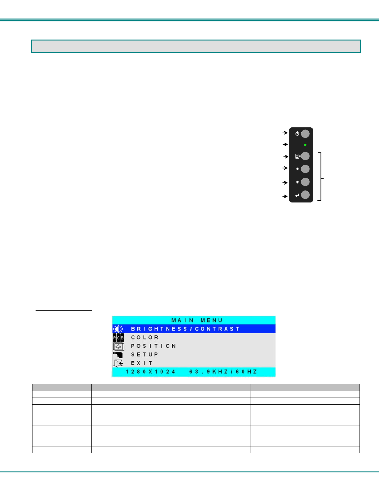
Standard Controls
The RACKMUX has 5 standard control buttons and a power LED. The 5 standard control buttons o perate as follows:
• The Power button turns the R ACKMUX LCD and backlight ON and OFF as desired.
• The Power LED located immediately below the Power button is a dual color
LED. It will illuminate with a green color when the RACKMUX is powered
ON and working properly. It will illuminate with a red color if the RACKMUX
is powered ON but there is no input signal detected.
• The
• The Up and Down Arrow buttons are used to navigate through the menus.
Once an item is highlighted, pressing the Menu button will select it.
Menu button is used to bring up the OSD menu where the various
settings of the LCD display can be adjusted. Once the OSD screen is
displayed, the Menu button is used to make selections within the menus.
See "OSD Control Menu" (below) for more on LCD display settings.
Move the cursor up or down as desired to highlight an item for selection.
Power
ON/OFF
Power LED
Menu
Up Arrow
Down Arrow
Select/
Auto Adjust
Controls for the
OSD Menus
• The Select button is used to make selections within the OSD menus when the OSD menu is ON. When the OSD menu is
OFF, the Select button will act as an
of the image on the monitor.
OSD Control Menu- 17 Inch VGA models (-V17)
The OSD (On Screen Display) Menu enables the user to select the desired characteristics of the LCD display. To activate the
OSD Menu, press the
10-60 seconds and it will automatically be cleared from the screen.
OSD Main Menu
Selection Purpose Range
Brightness/Contrast Increase/decrease panel brightness/contrast level 1-100
Color R,G,B color temperature control 1-100
Position
Setup
Exit Exit from the OSD control menu
Menu button (above). To turn the Menu back OFF, either select "EXIT" from the main menu or just wait
• Video Image horizo ntal and vertical position control
• Clock setting
• Phase control
• Control OSD Image positio n on screen
• Set time OSD will stay on screen before auto shutoff
• Select the language of the OSD menu
Figure 15- OSD Controls
Auto Adjust button to keep the user from having to use the menus to adjust the quality
1-100
-10 to 60 seconds
Several languages (see page 8)
13
Page 19
NTI RACKMUX-V17-N-8USBHD-IP RACKMOUNT DRAWER WITH USB KVM SWITCH AND KVM ON IP
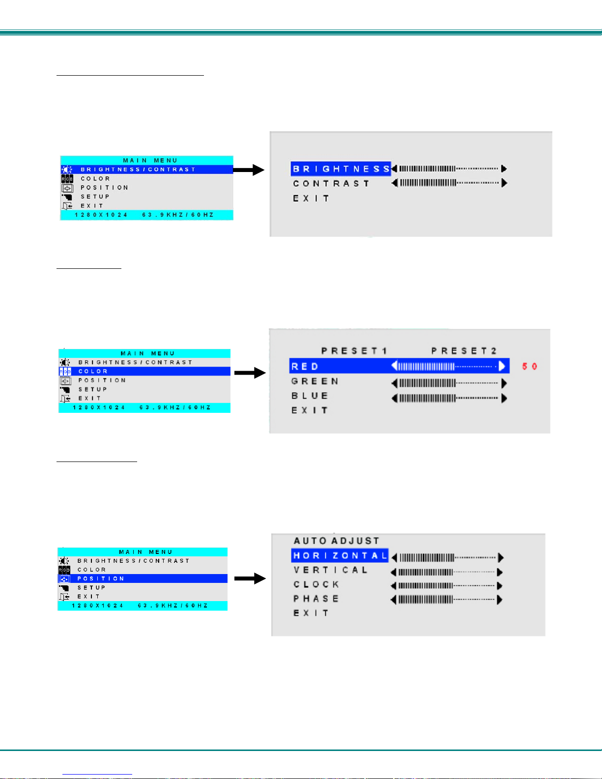
Brightness/Contrast Menu
Selecting the Brightness/Contrast menu will bring up a screen in which the user can adjust the brightness and contrast levels of
the LCD display. Using the
sections and press the
Select EXIT when finished to return to the Main Menu.
Up or Down Arrows to navigate the menu, highlight either the BRIGHTNESS or CONTRAST
Select button to choose the option to adjust. Then use the Up or Down Arrow to adjust the setting.
Color Menu
Selecting the Color menu will bring up a screen in which the user can adjust the Red, Green, and Blue color levels (values from 1-
100) of the LCD display. With the RED, GREEN, or BLUE sections highlighted, (use the
them), press the
Select EXIT when finished to return to the Main Menu.
Select button to choose the option to adjust. Then use the Up or Down Arrow to adjust the setting.
Up or Down Arrow to move between
Position Menu
Selecting the Position menu will bring up a screen in which the user can select AUTO ADJUST to automatically adjust the
horizontal and vertical position of the displayed image on the monitor, as well as adjust the clock and phase settings if they are not
correct. The user can also individually adjust these settings if so desired. With any of the sections highlighted, (use the
Down Arrow to move between them), press the Select button to choose the option to adjust. Then use the Up or Down
to adjust the setting as needed. Select EXIT when finished to return to the Main Menu.
Arrow
Up or
14
Page 20

NTI RACKMUX-V17-N-8USBHD-IP RACKMOUNT DRAWER WITH USB KVM SWITCH AND KVM ON IP
Setup Menu
Selecting the Setup menu will bring up a screen in which the user can adjust
OSD POSITION-the position of the OSD menus on the LCD display
OSD TIME-the length of time the user can be idle before the OSD menu automatically exits (adjustable from 10
to 60 seconds)
LANGUAGE-the language th at the OSD menus will be presented in
With the item highlighted, (use the Up or Down arrow to move between them), press the Select button to choose the option to
adjust. Then use the Up or Down Arrow to adjust the setting as needed. Select EXIT when finished to return to the Main
Menu.
OSD Image can be moved
to different points on the
display
15
Page 21

NTI RACKMUX-V17-N-8USBHD-IP RACKMOUNT DRAWER WITH USB KVM SWITCH AND KVM ON IP
KEYBOARD FUNCTIONS
The keyboard on the RACKMUX-Vxx is a standard condensed Windows format. To reduce the keyboard size, some keys have
been assigned multiple functions, accessible via the "Fn" key. This section will describe which keys have multiple functions and
how to enable them. Use the LEDs to know what special features are enabled.
Function Key Operation
The Function (“Fn”) key provides several special functions on the RACKMUX keyboard, including:
enabling otherwise standard keyboard keys to be used as the keys of a numeric keypad
enabling multi-function keys to change operation
enabli ng the “T” key to act as a mode key to toggle between USB and PS/2 keyboard/mouse mode
To turn ON (lock) the Function key, press the “Fn” key twice quickly (double-click). The “Fn” LED will illuminate.
To turn OFF (unlock) the Function key, press the “Fn” key twice quickly again. The “Fn” LED will turn OFF.
Note: The "Fn" key will also operate similar to the shift key (with only momentary effect). Press and hold the "Fn" key
prior to pressing the special function key. The "Fn" key will remain active as long as it is depressed.
Esc
~
`
F2
F1
!
1
F3
F4
@
2
#
$
3
4
F6
F5
%
5
F7
F8
F9
&
^
7
6
*
8
789
F10
(
9
F11 F12
)
0
Tab
WE R
Q
CapsLock
ASDFGH JK L
Shift
ZXCVB
T
YU I OP
123
M
N
654
<
,
Ctrl
Fn
Alt
Alt
Function Key to enable additional key functions
Num Lk
Insert Delete
Prt Sc
+
=
}
{
]
[
Enter
:
"
;
'
+
*
>
.
?
Shift
/
.
/0
Ctrl
Home
Sys Rq
Backspace
Enter
Pg Up
Pause
BreakScr Lk
\
EndPg Dn
1
On= NumLock
is locked
Figure 17- Keyboard LED Indications
Figure 16- US(English) Keyboard Layout
On= PS/2
Keyboard/Mouse
mode
On= CapsLock
is locked
A
On= Scroll Lock
is locked
On= Function
Key feature
is ON
Fn
On= USB
Keyboard/Mouse
mode
16
PS/2
Page 22

NTI RACKMUX-V17-N-8USBHD-IP RACKMOUNT DRAWER WITH USB KVM SWITCH AND KVM ON IP
Numeric Keypad Option
This RACKMUX has a standard Windows keyboard with 17-key numeric keypad.
The Function (“Fn”) key, (page 16) is only used to toggle between PS/2 and USB keyboard/mouse mode (page 18). W hen using
the RACKMUX-V17-N-8USBHD-IP, the RACKMUX should always be left in USB mode.
Note: When the Numeric Keypad is present, the "Fn" key does not lock. Instead, the “Fn” key operates similar to the
shift key (with only momentary effect).
F1
Esc
!
~
1
`
Tab
Q
Caps Lock
Shift
Fn
Ctrl
Function Key
F2
F3
F4
@
#
2
3
WE R
$
4
F6
F5
%
5
F7
F8
F9
F10
&
^
7
6
T
YU I OP
(
*
9
8
F11 F12
)
0
ASDFGHJKL
<
ZXCVB
Alt
M
N
,
Alt
:
;
>
.
PrtSc
SysRq
{
[
?
/
Insert
Scroll
Pause
Delete
Break
Lock
+
Backspace
=
}
]
"
Enter
'
Shift
Home
Page
\
Up
Page
Down
End
Num
Lock
/
789
Home Pg Up
456
123
End
0
Ins
*
PgDn
.
Del
-
+
Enter
Figure 18- U.S. (English) keyboard with numeric keypad
Esc
`
Tab
Caps Lock
Fn
Shift
F2
F1
!
1
Q
F3
F4
"
2
$
3
4
WE R
F6
F5
%
5
F7
F8
F9
&
^
7
6
T
YU I OP
*
8
ASDFGHJK L
ZXCVB
Ctrl
Alt
\
M
N
F10
AltGr
(
9
F11 F12
)
0
<
,
PrtSc
SysRq
{
[
:
@
;
'
?
>
.
/
Insert
Figure 19- U.K. (English) keyboard with numeric keypad
Pause
Scroll
Lock
+
Backspace
=
}
]
Break
Delete
Home
~
Page
Up
#
Num
Lock
/
*
789
Home
PgUp
-
+
Enter
Shift
Page
Down
End
456
123
End
0
Ins
PgDn
.
Del
Enter
17
Page 23

NTI RACKMUX-V17-N-8USBHD-IP RACKMOUNT DRAWER WITH USB KVM SWITCH AND KVM ON IP
Esc
Tab
?
\
Druck
S-Abf
F2
F1
!
1
^
F3
"
2
2
3
3
F4
$
4
F5 F6 F7
%
&
6
5
/
7 {
F8
F9 F10
(
8 [
)
9 ]
F11 F12
=
0 }
Q
WE R
@
T
ZU I OP
U
ASDFGH JK L
O
A
YXCVB
N
Strg
Fn
>
Alt
<
;
:
,
M
u
AltGr
.
Einfg
Rollen
*
+ ~
Pause
Untbr
Entf
Pos1
Bild
'
#
Bild
Ende
Num
789
Pos1
456
123
Ende
0
Figure 20- German keyboard with numeric keypad
/
Bild
Bild
-
*
+
Enter
.
Entf Einfg
PS/2-USB Keyboard/Mouse Mode
The RACKMUX keyboard and mouse can be configured to connect to either a PS/2 or USB enabled CPU. At initial power ON
from the factory, the keyboard will be in USB mode.
Note: There is no reason to toggle this model RACKMUX to PS/2 mode but this instruction is provided in the event USB
mode is inadvertently changed to PS/2 mode. If this happens, the keyboard and mouse will lose their ability to function.
Toggle back to USB mode to restore functionality.
1. To toggle the keyboard to USB mode, depress and hold the “Fn“ key (“Fn” LED will illuminate) and the “T” key for at
least 7 seconds. Release both keys.
2. To toggle the keyboard back to PS/2 mode, press and hold the “Fn” and “T” keys again for at least 7 seconds. Release
both keys.
Note: In the event of a power failure, the RACKMUX will power up the keyboard in the mode it was last configured for.
18
Page 24

NTI RACKMUX-V17-N-8USBHD-IP RACKMOUNT DRAWER WITH USB KVM SWITCH AND KVM ON IP
USING THE UNIMUX USB KVM SWITCH
Basic Operation
Once the UNIMUX is properly connected, the UNIMUX will enable a connection to be made between the CPUs attached to its
CPU ports and the RACKMUX keyboard, monitor and mouse.
The UNIMUX can be controlled by two methods:
• OSD Control via keyboard using the RACKMUX
• RS232 control (see page 40)
OSD Control
OSD control of the UNIMUX can be achieved using OSD Command Mode. Command Mode is operated using the keyboard and
mouse in conjunction with OSD menus superimposed onto the monitor.
By pressing <Ctrl> + < ` > (accent key), the user can enter Command Mode. Once in Command Mode, typing a series of
commands will cause the UNIMUX to connect the user to any one CPU connected to the switch. Pressing the <Esc> key will exit
Command Mode.
19
Page 25

NTI RACKMUX-V17-N-8USBHD-IP RACKMOUNT DRAWER WITH USB KVM SWITCH AND KVM ON IP
OSD CONTROL
OSD superimposes a menu system on the user’s video screen with a list of all connected CPUs. OSD allows CPUs to be named
(with up to 12 character names). OSD then allows selection of CPUs by that name. Connected CPUs can be listed by name or
by port number. OSD Search Mode enables the user to type in the first few characters of the CPU's name and the OSD will
locate it. HELP screens assist with all OSD functions.
Guidelines for Navigating OSD Menus
Throughout this manual, various rules apply to navigating the menus used to control and operate the UNIMUX.
• OSD menus can be navigated using the mouse, the arrows on the keyboard, hot keys (highlighted in red) and the
<Page Up>, <Page Down>, <Home>,<Tab> and <End> keys.
- The <up arrow> and <down arrow> moves the cursor up or down one line item at a time in a scrollabl e
window, or between menu items in a menu item list
- The <left arrow> and <right arrow> will move the cursor left or right through menu items or while in
editable fields (such as when editing port names)
- <Page Up> and <Page Down> increase/decrease the listed ports by one page at a time
- <Home> will jump to the beginning of the list
- <Tab> will jump between selectable fields, left to right
to move between menu items
- <Shift>+<Tab> will jump between selectable fields, right to left
- <End> will jump to the end of the list.
• Only alphabetic and numeric characters can be typed in the OSD menu fields
• Positioning the mouse cursor over a menu function or CPU name will highlight the background (green highlight for
menu functions, cyan or light blue for CPUs)
• The scroll bar can be used by clicking on the corresponding up and down arrow above and below the scroll bar.
• The mouse wheel may be used to move the selection bar
• The <Shift> key must be used to enter an uppercase letter within all OSD menus.
• Clicking on a listed CPU while in Command Mode will connect the user to that CPU.
• Available functions will have white characters with one red character. The red character corresponds to a keyboard
“hot key”. Hot keys are not case sensitive. Functions that are not available will be transparent.
• When changing characters for names, passwords, or values within an edit field, click on the field or select and press
<Enter> to enter the field for editing, and press <Enter> again to exit th e edit field.
• To exit (and step back 1 menu) from any menu, press <Esc> on the keyboard .
• All screens that include “F1:Help” for context-sensitive help will also respond to pressing the <F2> key to provide
“Global Help” screens with basic menu navigation help.
Security Option
The security option in the OSD Control of the UNIMUX USB KVM switch enables an administrator to control access to CPU ports
for each user. Up to 63 users can be created. These users have controlled access to any CPU. Only the administrator can
activate or deactivate the security features on the user port. Finally, the administrator can set a maximum idle time value after
which the current user will be logged out and the login screen displayed again if the user has no activity. The current security
status, idle time out, and scan dwell time are all saved and will be restored whenever power to the switch is cycled OFF, then ON.
To reset the administrator's password call NTI and have the device serial number of the UNIMUX available. For more on
security, see page 27.
20
Page 26

NTI RACKMUX-V17-N-8USBHD-IP RACKMOUNT DRAWER WITH USB KVM SWITCH AND KVM ON IP
Initial startup
When the UNIMUX is first powered ON, a splash screen similar to the following will appear:
Press any key and the UNIMUX will connect you to the first CPU port with a connect ed CPU that is powered ON.
To access Command Mode and connect to a different port or perform other user access functions (see below), press <Ctrl> +
<`> (accent/tilde key).
User Access Functions
Command Mode
In order to control the switch with the keyboard, Command Mode must be enabled. To enable Command Mode from the
keyboard:
(ACCENT/TILDE
Press
All the status lights on the keyboard will illuminate to indicate that Command Mode is enabled. At this point, the Command Mode
menu will be displayed.
The Command Mode menu (see Figure 21) lists all CPUs by name and port number. Only 8 ports are listed on the screen at a
time. To view the other portions of the list, scroll using the arrow keys on the keyboard or use the mouse to click on the arrows on
the scroll bar in the OSD menu. When the Command Mode main menu is displayed, the first displayed port in the list will be the
port the current user is connected to, followed by the next seven consecutively numbered ports. (Alternatively the list may be
sorted alphabetically- press the letter <O> to toggle sort method.) The names of accessible ports are displayed with blue
characters. If Security is activated, the access rights for the user logged-in may not include all ports. Names of restricted access
ports are displayed in black.
Ctrl
+
~
`
`
KEY)
21
Page 27

NTI RACKMUX-V17-N-8USBHD-IP RACKMOUNT DRAWER WITH USB KVM SWITCH AND KVM ON IP
U
I
An arrow to the left of a port number in the list indicates
the port the user is currently connected to. From
left to right, the columns display the following:
• Port Number
• Port Name
• Power Status of the CPU (ON/OFF)
Note: “NAC” indicates a non-accessible
computer for that user
• The actual user number (1-8) connected to the CPU.
• If no user is connected to a CPU, the user number is
replaced by a "–" (dash).
Selection
Bar
Cursor
Port Number
Port Name
Figure 21- Command Mode main menu-User
Note: While in Command Mode, the numbers on the NUM PAD on the keyboard are not active. If numbers are required
while in Command Mode, use the numbers on the main key bank.
The list below describes the command functions available from the keyboard within the OSD mode of control after entering into
Command Mode:
Function Keystroke
Select the previous port
Select the next port
Go to specific port- Press any valid number from 1-
1024 to connect to a desired port.
Increases the ports listed by 1 page
Decreases the ports listed by 1 page
Enter “Settings” menu
Toggle ports listed to view by port number or
alphabetically by port name
Enable/disable Scan Mode
Enable/disable Broadcast Mode
Enter Administrator menu
(only available if the Administrator is logged in)
Select the first port on the switch
Select the last port on the switch
Display Help menu
Global Help- display window navigation tips used
throughout all menus
Display port information- when pressed, a window
displays the port name and its position in the
configuration structure by level and port number
Update configuration- use to update the information
describing the structure of the cascaded switches.
Use if a slave is powered-ON or OFF at any time after
initial startup
up arrow
down arrow
port # - Enter
Page Down
Page Up
T
O (letter, not
number)
Ctrl + S
Ctrl + B
A
Home
End
F1
F2
F3
R or F5
Note: The user must exit
Command Mode to type to a CPU.
To exit Command Mode press
<Esc> on the keyboard.
ser
Scroll Bar
Power
Menu
tems
22
Page 28

NTI RACKMUX-V17-N-8USBHD-IP RACKMOUNT DRAWER WITH USB KVM SWITCH AND KVM ON IP
Function Keystroke
Enter Find Mode, add a character to search string
and select the CPU’s name that matches best.
F
Type any alphabetical or numeric character (A-Z, 0-9)
Note: use is not case sensitive
Switch to selected port
Logout (you will be prompted for confirmation)
Exit Command Mode
Enter
L
Esc
Figure 22- Administrator’s main menu
Settings
To enter the Settings menu (see Figure 23) press <T> from the Command Mo de menu. The list below describes the Settings
menu functions available from the keyboard:
Function Keystroke
Open OSD Settings screen
Go to Broadcast list
Go to Scan list
Change the scan dwell time period
Enter any value from 002-255
(for more on this-see “Scan Mode”
page 25)
Enable/Disable right mouse button
click emulation with Apple 1-button
mouse (see “Mouse Click
Equivalents” on page 38 for more)
Exit from Settings menu
Return to Main menu
When the <T> is pressed, the current value of the scan dwell time is selected with an edit field (see Figure 23) . The user can
introduce a new value for scan dwell time and press <Enter> to save it or <Esc> to exit. Any value between 002 and 255
(seconds) is acceptable.
O
B
S
T
R
Esc
Figure 23- Settings menu
23
Page 29

NTI RACKMUX-V17-N-8USBHD-IP RACKMOUNT DRAWER WITH USB KVM SWITCH AND KVM ON IP
OSD Settings
The OSD Settings screen enables the user to adjust the height of the OSD screen on the monitor and the position of it. The
position can be adjusted both horizontally, as well as vertically. Press <O> from the Settings menu (page 23) to open the OSD
Settings screen.
Function Keystroke
Make OSD window taller
Make OSD window shorter
Move OSD window vertically
Move OSD window horizontally
Exit and save OSD Settings
Figure 24- OSD Settings screen
T
S
up or down
arrow
left or
right arrow
Esc
Find Mode
Find Mode is enabled by typing any alphabetical or numeric characters while in the Command Mode mai n menu, or by pressing
<F> while in supporting menus.
Find Mode allows the user to enter and maneuver through a list of CPU names. The CPU name best matching the characters
typed is selected. The list of CPUs may also be searched for a specific (or similar) name. The Find Mode function is not case
sensitive. The following commands are valid when the search option has been invoked from Command Mode.
Function Keystroke
Erase previous character in search
name
Add a character to the search
string and select the best
matching CPU name
Exit Find Mode
Figure 25- Find Mode in use
Backspace
A-Z, 0-9
(upper or
lower case)
Esc or Enter
24
Page 30

NTI RACKMUX-V17-N-8USBHD-IP RACKMOUNT DRAWER WITH USB KVM SWITCH AND KVM ON IP
Help Mode
To enter Help Mode press the <F1> key from the Command Mode
menu (see page 13).
Help Mode displays a list of commands with a short explanation of
their function. The following options allow the user to quickly
obtain information on any command
.
Function Keystroke
View the previous page of help
if available
View the next page of help if available
Exit Help Mode
Page Up
Page Down
Esc
Figure 26- Main Menu help screen
Scan Mode
Using Scan Mode, the user can automatically switch from one CPU to another in predetermined config urable time intervals. The
CPU ports to be scanned are easily selected provided the user has access to them. At initial startup, the user as access to all
CPU ports by default.
To activate or deactivate Scan Mode press <Ctrl> + <S> from the Command Mode menu. The text shown in the menu (see
Figure 22) will toggle between “Scan=N” and “Scan=Y”, each time the
shown, Scan Mode is active. When “Scan=N” is shown, Scan Mode is OFF.
From the Settings menu (see page 23) press <S> to access the “Scan List”. The Scan Li st enables the user to select specific
ports to be active in Scan Mode. While active, the user will have full device control of the con nected port. Only the selected
ports will be scanned in Scan Mode.
The “Scan List” is a check list with all the port numbers displayed
<Ctrl> + <S> keys are pressed. When “Scan=Y” is
• unchecked box = the corresponding port is
• checked box = the corresponding port
not in the scan list
is in the scan list
From the “Scan List” the user can:
• toggle the state of the selected port (press <Spacebar>)
• select all ports to be scanned (press <A>)
• deselect all ports so that none are scanned (press <N>)
• find a specific port to either select or deselect (press <F> ,
then any alphabetical or numeric character to locate the desired port).
Figure 27- Scan List
A port is skipped from the scan cycle if one of the following conditions is true:
- the port is not in the Scan List
- Security Mode is enabled and the user does not have access rights to the port
- the CPU connected to the port is OFF
25
Page 31

NTI RACKMUX-V17-N-8USBHD-IP RACKMOUNT DRAWER WITH USB KVM SWITCH AND KVM ON IP
When switching to a new port the port name is displayed by OSD in the left upper corner of the monitor for 5 seconds or until a
key is pressed or the mouse is moved, whichever comes first. The scan dwell time is programmable from 2 to 255 seconds
(default time-out period is 5 seconds). While using the mouse, keyboard or touchscreen the scanned port becomes active and
scanning is stopped. The switch will resume scanning after a period of user inactivity determined by the scan dwell time. See
Settings Menu on page 23 for configuring the scan dwell time.
To return to the Settings menu, press <Esc>. The scan selection list is automatically saved.
Note: The scan dwell time set by the user affects all users.
Note: The keyboard, mouse and touchscreen must remain idle for the full scan dwell time before the switch selects the
next active port.
Broadcast Mode
To activate or deactivate Broadcast Mode press <Ctrl> + <B> from the Command Mode menu. The text shown in the menu
(Figure 22) will toggle between “BCast=N” and “BCast=Y”, each time the <Ctrl> + <B> keys are pressed. When “BCast=Y” is
shown, Broadcast Mode is active. When “BCast=N” is shown, Broadcast Mode is OFF.
Broadcast Mode enables the user to type characters to more computers simultaneously. From the Settings menu (see page 23)
press <B> to access the “Broadcast List” where the user can edit the list of ports that receive data in Broadcast Mode.
The “Broadcast List” is a check list with all the port numbers displayed
• unchecked box = the corresponding port is
• checked box = the corresponding port
not in the broadcast list
is in the broadcast list
From the “Broadcast List” the user can:
• select all ports to be broadcasted to (press <A>)
• deselect all ports so that none are broadcasted to (press <N>)
• select only a limited number of ports to be broadcasted to
• find a specific port to either select or deselect (press <F> ,
then any alphabetical or numeric character to locate the desired port).
Figure 28- Broadcast List
A port doesn’t receive broadcast data if one of the following conditions is true:
- the port is not in the Broadcast List
- Security Mode is enabled and the user does not have access rights to the port
Note: The user must type somewhat slowly when in Broadcast Mode (less than 20 wpm) and cannot use the
<Backspace> key.
Note: The mouse and touchscreen will be disabled while in Broadcast Mode
To return to the Settings menu, press <Esc>. The broadcast selection list is automatically saved.
.
Normal Mode
When the UNIMUX switch is not in Command, Scan, or Broadcast mode and the OSD control is not active on the monitor, the
user is in Normal Mode, controlling the CPU to which the user is connected through the UNIMUX switch.
26
Page 32

NTI RACKMUX-V17-N-8USBHD-IP RACKMOUNT DRAWER WITH USB KVM SWITCH AND KVM ON IP
Security
Enabling Security
To enable the security feature the administrator must first enter Command Mode. If the Command Mode menu is not already
displayed, press <Ctrl> + <`> (accent/tilde key). The OSD menu will automatically appear on the monitor.
To login as the administrator, the user must first logout by pressing <O>, and then <Y> to confirm. A login prompt will appear.
Password and User Name
The factory settings are:
• default user name = <root>
• default password = <nti>
Note: The username for the administrator cannot be changed
from "root”.
Figure 29- User login screen
Note: The <F1> Autologin key (see Figure 31) is only for use by users other than the administrato r, an d is only displayed
and available for use if security is not enabled.
With a valid login, the user will be connected to the first CPU that is powered-ON. To enter Command Mode, press <Ctrl> +
<`> (accent/tilde key). The OSD menu will automatically appear on the monitor.
Figure 30- Administrator's main menu
The administrator will activate security (after logging in) by pressing <A>-<S>-<S>-<E> (see page 35).
Once logged-in, follow the instructions on page 28 for setting up users and changing the password. Once the password is setup,
if it is lost or forgotten the administrator will have to contact NTI for assistance on clearing the password and set it up again. The
administrator can setup each of the users and the limitations of their use of the individual CPUs using the administration menus.
When a standard user powers up the UNIMUX with security enabled, the login screen will a ppear. Enter the user name and
password as set by the administrator. Unless a valid user name and password are entered, the login screen will remain on the
monitor. For more on “User Login”, see page 28.
27
Page 33

NTI RACKMUX-V17-N-8USBHD-IP RACKMOUNT DRAWER WITH USB KVM SWITCH AND KVM ON IP
User Login
User Login Mode requires a user to login with a user name and password from the list created by the administrator. T he user will
only be able to login if security is enabled. With security enabled, the user will be locked to the current CPU and the login
screen will remain on the monitor until the user logs in.
Function Keystroke
Autologin
(This is only available (but must be used
when available) if security for the
connected port is disabled)
Add a character to the
user name/password
See note below
Remove previous character
from the user name/password
Submit user name/password
Move from Name to Password field
If the password submitted is incorrect, the user will not be able to proceed.
If the password submitted is correct, the user will proceed to Normal Mode
(see page 17).
Figure 31- User Login screen with security disabled
Once a user name and password is accepted, the UNIMUX will connect to the first CPU that is powered-ON and the user has
access to. To enter Command Mode, press <Ctrl> + <`> (tilde/accent key).
F1
See note below
A-Z /0-9 or Shift + A-Z
(upper and/or lower case
characters)
Backspace
Enter
Tab or Enter
See the Command Mode functions described on page 21 to control the system of CPUs within the limitations as determined by
the administrator.
Note: If security is not enabled, the message “Press F1 to Autologin” will appear in the login screen. While security is
disabled, a standard user must press <F1> (see Figure 31) to access the switch. Only the administrator can log in
using the name and password when security is not enabled.
Additional OSD Modes Available With Security Enabled
Administration Menu
To access the Administration Menu press <A> from the Administrator’s Main menu (see Figure 30). The Administration Menu ca n
be accessed only when the administrator is logged-in. Users other than th e administrator are not able to enter the Administration
Menu.
If a different user is logged-in, log-out by pressing <L> from the Main menu,
then log-in as
Administration Mode allows the administrator to use the following functions:
Function Keystroke
Go to System Configuration menu
Go to Ports Configuration menu
Go to User Configuration menu
Change administrator’s password
Display Usage Statistics
Ethernet Configuration
Exit from Administration Menu
Return to Command Mode
Administrator. (See page 27, "Enabling Security".)
S
P
U
C
D
E
Esc
Figure 32- Administration Mode Menu
28
Page 34

NTI RACKMUX-V17-N-8USBHD-IP RACKMOUNT DRAWER WITH USB KVM SWITCH AND KVM ON IP
System Configuration
To enter the System Configuration menu: press <S> from the Administration menu. The System Configuration menu can on ly be
accessed when the administrator is logged-in.
Function Keystroke
Change Idle Timeout
Change OSD Blank Timeout
Change Alternate Command Hot Key
(See page 34 for details)
Reset the port names to default settings
*You will be prompted to confirm this selection*
Note: The UNIMUX must be power cycled or the
OSD Refreshed (main menu) for the reset to
take effect.
Configure the Keyboard Language
Open Security Configuration menu
Serial Baud Rate
Serial Address
Exit from System Configuration menu and
return to Administration Menu
Figure 33- System Configuration menu
I
O
A
R
K
S
B
E
Esc
Port Configuration
To enter the Port Configuration menu: press <P> from the Administration menu. The Port Configuration menu can only be
accessed when the administrator is logged-in.
The port configuration screen is used to edit the names of ports and to configure ports to be compatible with MAC or non-MAC
CPUs. If the port will have a MAC CPU connected, use the mouse to click on the box associated with the port to place a check
mark in the box.
Note: If a port is configured as connected to a non-MAC CPU, but is in fact connected to a MAC CPU, the mouse will still
work as a generic mouse. No special functions provided by software drivers will be available.
Note: MAC mode must be enabled on any CPU ports that are connected to a CPU through an NTI ST-C5USBV extender.
Function Keystroke
Open an edit field for the selected port to rename the
port (see Figure 34). Names of CPUs can be up to
12 characters in length. Characters typed can be
upper or lower case.
Press <Enter> a second time to save the changes.
Configure all ports for MAC CPU connection
Configure all CPUs for non-MAC CPU connection
Open field in which you can type characters to quickly
locate a specific port to be configured
Toggle the selected port between MAC and non-MAC
configuration
Open Help window for this topic
Exit from System Configuration menu and Return to
Administration Menu. All changes made will be
saved
Enter
A
N
F
Spacebar
F1
Esc
Figure 34- Port Configuration menu
- To save the change to characters in an edit field, press <Enter>.
- To exit an edit field without saving the changes, press <Esc>.
29
Page 35

NTI RACKMUX-V17-N-8USBHD-IP RACKMOUNT DRAWER WITH USB KVM SWITCH AND KVM ON IP
User Configuration
To enter the User Configuration menu: press <U> from the Administration menu. The User Configuration menu can only be
accessed when the administrator is logged-in.
The User Configuration screen lists the users configured to access the UNIMUX. Up to 63 users can be assigne d access.
To assign a user name, password, and port access control, select the user number or an empty record and press <Enter>, <E>,
or click it with the mouse.
Function Keystroke
Select previous user in the list
Select next user in the list
Scroll to previous 8 names
Scroll to next 8 names
Edit account for selected user
Exit and return to previous menu
Figure 35- User Configuration
up arrow
down arrow
Page up
Page down
E
Esc
Edit User Account
The User Account mode (see Figure 36) enables the administrator to:
- add a new user
- remove an existing user
- edit the settings for an existing user
Function Keystroke
Place edit field around the name- enabling it to be
edited
If no name is entered, a default name “userXX”
(where XX is the user number) will be entered
Open an edit field to insert a user password- up to 15
characters in length
If no characters are entered, no password will be
required for that user
Usable characters for Name or Password
(Upper and lower case characters can be used)
Open an edit field to confirm the password by
retyping
Close an edit field
Open access control list for the user, to assign ports
the user will be able to connect to
For new users, by default, no ports are user
accessible unless selected by the administrator
Delete all account information for the selected user
Exit and return to previous menu
Changes made will be saved automatically
N
P
A-Z /0-9 or
Shift + A-Z
C
Enter
A
D
Esc
Figure 36- User Account menu
Note: To change the characters of a name while in the edit field, type th e new characters or use the <Spacebar> to
overwrite the existing characters. Pressing the <Delete> key will have no effect on existing characters and the
<Backspace> key will only work if the cursor is at the end of the edit field. Use the <left arrow>, <right arrow>, <home>
or <end> keys to move the cursor while in editable fields.
30
Page 36

NTI RACKMUX-V17-N-8USBHD-IP RACKMOUNT DRAWER WITH USB KVM SWITCH AND KVM ON IP
User Access Control
To enter the Access Control list for a user, press A from the User Account screen for that user. From the Access Control list the
administrator can:
• select all ports to have access to
• deselect all ports so that none can be connected to
• select only a limited number of ports to be accessed
The Access Control list is a check list with all the port numbers displayed
• unchecked box = the corresponding port is
• checked box = the corresponding port
not in the access list
is in the access list
Function Keystroke
Toggle the state of the selected
Spacebar
check box
Select the next or previous port
Quickly place check marks in all
up or down arrow
A
boxes
Quickly remove check marks from all
N
boxes
Open Help window for this topic
Exit and return to previous menu
F1
Esc
Changes made will be saved
automatically
Figure 37- Access Control list
Change Administrator Password
To change the Administrator Password, press <C> from the Administration menu.
The Admin Password menu (see Figure 38) enables the administrator to change his password. Two edit fields are available, one
for password, the other for verify password. The password can be up to 15 characters in length.
Note: The default password for the administrator is “nti”.
Function Keystroke
Switch between Password and
Confirm (password) fields
Add character to password string
or confirm string
Delete previous character in
edited string
Save new password. (The
administrator will be prompted
for a Yes or No confirmation)
Exit and return to previous menu
Note: If the confirmation password does not match the first password entered, the message “INVALID PASSWORD” will
be displayed when you try to save it.
Tab
A-Z, 0-9
(upper or lower case)
Backspace
S
Esc
Figure 38- Administrator password menu
31
Page 37

NTI RACKMUX-V17-N-8USBHD-IP RACKMOUNT DRAWER WITH USB KVM SWITCH AND KVM ON IP
Display Usage
To display usage statistics for the UNIMUX, press <D> from the Administration menu.
The Display Usage page shows the user how many times the UNIMUX has been power cycled and how many total ho urs it has
been powered ON. The counters for these statistics can be reset to 0 by pressing <F7> to reset the number of power cycles or
<F8> to reset the hours of usage.
Figure 39- Usage Statistics Page
Ethernet Configuration
To configure the ETHERNET port settings on the UNIMUX for controlling the switch via Telnet Interface (page Error! Bookmark
not defined.
Function Keystroke
Change the IP Address
Change the Subnet Mask
Change the Gateway
Change the port number
Exit and return to previous menu
Figure 40- Ethernet Configuration
If the Ethernet feature is not present in the UNIMUX, the message “Ethernet Card Not Present” will appear at the bottom of
this menu in Figure 40.
If the Ethernet port is present but not connected, the message “Ethernet Card Present, Status: Not Connected” will
appear at the bottom of the Ethernet Configuration menu (Figure 40).
Note: The Ethernet port is not available when the CAT5 option is present.
), press <E> from the Administration menu. The default values are shown in Figure 40.
Not supported in this product
I
S
G
T
Esc
32
Page 38

NTI RACKMUX-V17-N-8USBHD-IP RACKMOUNT DRAWER WITH USB KVM SWITCH AND KVM ON IP
Idle Timeout
The idle timeout is the amount of time that the user can be idle while in Command Mode before the user is automatically logged
out. The idle timeout can be set to any value from 000 to 255 minutes. A value of 000 will disable it. After the idle timeout
period has elapsed, the login screen will appear.
To change the Idle Timeout setting,
1. press <I> from the System Configuration menu (page 29) to display the
edit field around the value (see Figure 41)
2. enter the desired value (000-255 minutes)
3. press <Enter> to save it and move to the next field
4. press <Esc> to exit the System Configuration menu
Figure 41- Change value of Idle Timeout
OSD Blank Timeout
The OSD Blank Timeout is the amount of time that the user can be idle while in Command Mode before the OSD menu will
disappear. The time period can be set to any value from 000 to 255 minutes. A value of 000 will disable it. After the OSD
disappears when the configured time period has elapsed, the user can make it reappear by either pressing a key on the keyboard
or moving the mouse.
To change the OSD Blank Timeout setting,
1. press <O> from the System Configuration menu to display the
edit field around the value (see Figure 42)
2. enter the desired value (000-255 minutes)
3. press <Enter> to save it and move to the next field
4. press <Esc> to exit the System Configuration menu
Figure 42- Change the value of OSD Blank Timeout
33
Page 39

NTI RACKMUX-V17-N-8USBHD-IP RACKMOUNT DRAWER WITH USB KVM SWITCH AND KVM ON IP
Alternate Command Hot Key
To enable the administrator to assign a key in addition to the <`> (accent/tilde key) to use with <Ctrl> to enter into OSD
Command Mode, an Alternate Command Hot Key option is provided. The default factory setting for this option is <`> (disabling
the option).
To select an Alternate Command Hot Key, press <A> from the System configuration menu (page 28). A window will open and the
administrator will be prompted to press a key. Any key
key, a confirmation message will appear. The administrator should press <Y> (Yes) to validate the key as the Alternate Command
Hot Key, or <N> (No) to select another key.
Pressing <Esc> will return to the Administration Mode menu.
Only the administrator is able to set or change the Alternate Command Hot Key. This function must be set individually for each of
the USB User Device ports on the UNIMUX USB KVM switch.
Note: The Alternated Command Hot Key does not replace the <`> (accen t) key, it just works as another way to enter into
Command Mode. After setting it, the user can enter into Command Mode either with <Ctrl> + <`> or with <Ctrl> +
<Alternate Command Hot Key> combination. To disable it, the administrator should set <`> as the Alternate Command
Hot Key.
except Ctrl, Shift, Alt, Tab, Esc, or Enter can be used. After pressing the
Figure 43- Alternate Command Hot Key selection window
Reset Port names
To erase all configured port names and return them to the factory-default names,
press <R> from the System Configuration menu. After pressing the key, a
confirmation message will appear. The administrator should press <Y> (Yes) to
validate the selection or <N> (No) to cancel it.
Pressing <Esc> will return to the Administration Mode menu.
The switch must be power cycled for the reset to take effect.
Figure 44- Press "R" to reset port names
34
Page 40

NTI RACKMUX-V17-N-8USBHD-IP RACKMOUNT DRAWER WITH USB KVM SWITCH AND KVM ON IP
Select Keyboard Language
To enter the Select Language menu (see F igure 45) press K from the System Configuration menu described on page 29. Only
the administrator has the Select Language menu option.
The Select Language menu enables the administrator to select a specific keyboard la nguage (country code) to be used.
Typically only SUN CPUs require a specific country code to be registered at boot up. (For other types of CPUs this feature may
have no effect.) A list of available languages is displayed and can be scrolled using the mouse (scro ll wheel) and/or <up arrow>,
<down arrow>, <Home> and <End> keys.
Figure 45- Select Language menu
• To manually pr ogram a specific language, select a language and press <Enter> (or click the left mouse button).
• To automatically detect the language of the keyboard, select "AutoDetect" and press <Enter> (or click the left
mouse button) . The list will advance to the actual detected keyboard language and that language will be programmed.
Some keyboards don’t have a country code. In this case the selection will remain in the “AutoDetect” position and the default
country code "00" will be programmed in the UNIMUX. If a specific country code is manually programmed, it will be the country
code for the switch, regardless of the actual country code of the connected keyboard. The programmed country code is saved in
memory and restored each time the UNIMUX is powered-ON. Because the CPUs that use country code (i.e. SUN CPUs) read it
at boot time, it is necessary to boot the CPU(s) after programming the country code.
Security Configuration
The UNIMUX can be configured to either have no security enabled such that any user can connect to the UNIMUX, or have
security enabled such that a user must have a login name and password in order to enter Command Mode and make a
connection with an accessible CPU. Only the administrator has access to Security Configuration.
Within Security Configuration, the administrator has three options:
Function Keystroke
Enable security just for the user port
that his currently connected through
Enable Global Security- security
enabled on all user ports
Disable Global Security- security
disabled on all user ports
Return to previous menu
U
E
D
Esc
Figure 46- Security Configuration
35
Page 41

NTI RACKMUX-V17-N-8USBHD-IP RACKMOUNT DRAWER WITH USB KVM SWITCH AND KVM ON IP
If Security is disabled and the user attempts to login to Command Mode
with the command key, the login screen will include the instruction
“Press F1 to Autologin”.
With security disabled, Autologin provides full access to all connected
CPUs and all users except the administrator must use it to login.
When security is enabled, Autologin is not available and the user must
login using the administrator assigned user name and password. The
user will have access to only those CPU ports as configured by the
administrator.
Figure 47- Login screen with security disabled
Serial Baud Rate
The serial baud rate for the UNIMUX can be changed by pressing <B> from the System Configuration menu. In order to control
the UNIMUX via RS232 (page 40), the baud rate must be set the same as the communication port on the control terminal
attached to the UNIMUX (page Error! Bookmark not defined.)
The baud rate value can be set to 115000, 57600, 38400, 19200, 9600, 4800, 2400, or 1200. A data protocol of 8 data bits, no
parity, and 1 stop bit is used for communications. With the edit field highlighted, press the <Left arrow> or <Right arrow>
to change the value of the baud rate.
Note: The baud rate can also be changed from the RS232 Command Protocol (see page 40).
For more on RS232 Control, see page 40.
Figure 48- Adjust Baud Rate
36
Page 42

NTI RACKMUX-V17-N-8USBHD-IP RACKMOUNT DRAWER WITH USB KVM SWITCH AND KVM ON IP
Serial Address
To allow multiple UNIMUXs to be controlled from a single control terminal, the RS232 control interface is designed to allow "daisy
chaining" up to 15 units. Each unit must be assigned a unique address. The unit address for the UNIMUX can be changed by
pressing <E> from the System Configuration menu. With the edit field highlighted, press the <Left arrow> or <Right
arrow> to change the value of the unit address. The address range is 1-15. For more on daisy chaining, see page 40.
Figure 49- Adjust Serial Address
37
Page 43

NTI RACKMUX-V17-N-8USBHD-IP RACKMOUNT DRAWER WITH USB KVM SWITCH AND KVM ON IP
Keyboard Mapping
The keyboard configuration of each CPU is saved in the UNIMUX switch. For example, if the CPU attached to Port 4 had CAPS
LOCK and NUM LOCK selected the last time that CPU was accessed, then they will automatically be set when that CPU is
accessed again.
Key Equivalents
Using the chart below, find the character needed to be typed on the CPU being accessed, then follow the row across for the
equivalent on the keyboard being used. (See Figure 50 on page 39 for reference.)
USB 101 WINxx MAC
(Apple USB)
L-Ctrl L-Ctrl L-Ctrl L-Ctrl
L-Alt L-Alt L-Option L-Alt
SB+F12 Application SB+F12 Compose
R-Alt R-Alt R-Option Alt-Graph
SB+Alt Windows Logo Command Meta
SB+R Arrow SB+R Arrow Power Suspend
SB = Space Bar
L and R = Left and Right keys when two keys are marked the same on a keyboard.
SUN
Mouse Click Equivalents
To emulate a right button click using Apple 1 button mouse, hold down the Command key ( ) while pressing the mouse
button.
Note: Right mouse button emulation must be enabled (see Settings on page 23) for this to work.
SUN’s 16 Extra Keys
101,WINxx,MAC
Keyboards
SB+F1 Stop (L1) Use the chart to the left to type SUN’s
SB+F2 Again (L2) additional 16 keys using a 101,
SB+F3 Props (L3) WINxx, or MAC (Apple)
SB+F4 Undo (L4) USB keyboard
SB+F5 Front (L5)
SB+F6 Copy (L6)
SB+F7 Open (L7)
SB+F8 Paste (L8)
SB+F9 Find (L9)
SB+F10 Cut (L10)
SB+F11 Help
SB+F12 Compose
SB + Up Arrow Vol +
SB + Down Arrow Vol -
SB + L Arrow Mute
SB + R Arrow Suspend SB= Space Bar
SUN Extras
38
Page 44

NTI RACKMUX-V17-N-8USBHD-IP RACKMOUNT DRAWER WITH USB KVM SWITCH AND KVM ON IP
Figure 50- Keyboard layouts
Help
Stop
Props
Front
Open
Find C ut
Esc
~
`
Tab
Caps Lock
Shift
Ctrl Alt
Esc
~
`
Tab
Caps Lock
Shift
Ctrl Alt
Windows Logo Ke y
Esc
Again
Tab
Undo
Caps Lock
Copy
Paste
Ctrl Alt
Enter
Shift
Alt
Typical 101 Keyboard
F1 F2 F3 F4 F5 F6 F7 F8 F9 F10 F11 F12
Enter
Shift
Alt
Application KeyWindows Logo Key
Windows Keyboard
esc
~
`
tab
caps Lock
shift
alt
control
option
Command Key
Apple USB Keyboard
Shift
Meta Key Meta Key
Backspace
Ctrl
Backspace
Ctrl
delete
return
Command Key
Backspace
Enter
Shift
Com-
Alt
pose
Graph
Print
Screen
SysRq
F12 F11 F9 F10 F8 F7 F6 F5 F4 F3 F2 F1
Scroll
Lock
Num
Lock
Pause
Break
Num
Lock
Power
Button
help home pg up pg dn
num
lock
=/
clear
Num
Lock
Enter
Enter
*
enter
Suspend
key
Enter
SUN USB Keyboard
39
Page 45

NTI RACKMUX-V17-N-8USBHD-IP RACKMOUNT DRAWER WITH USB KVM SWITCH AND KVM ON IP
RS232 CONTROL
RS232 enables the UNIMUX to be remotely controlled via RS232. To control the UNIMUX via RS232 the user has three options:
• write a program that runs on a PC using the Command Protocol (page 42)
• use the NTI Switch Control Program (page 43) provided on the CD
• use the SerTest or RMTEST programs (pages 43 and 45) provided on the CD
Remote Connection
The RS232 Interface is designed to meet the RS232C standard and can be controlled from any CPU or other controller with an
RS232 communications port. The pin-out for the RJ45 connector on the unit is as follows:
RS232 (RJ45) CONNECTOR
PIN SIGNAL FUNCTION
1 - No connection
2 - No connection
3 RX+ Receive data (TXD at host)
4 GND Ground
5 - No connection
6 TX+ Transmit data (RXD at host)
7 - No connection
8 - No connection
NOTE: Security must be disabled or user access granted on the port(s) to be selected by RS232 control.
A 5 foot patch cable and two adapters, RJ45-to-DB9 and RJ45-to-DB25, have been provided for connection to most CPUs (see
page Error! Bookmark not defined.). To daisy chain multiple units, connect a Matrix-Y-1 cable (sold separately) between the
CPU and the first switch, and between each switch (as shown in Figure 51).
Baud Rate
The baud rate can be changed using the OSD menu (page 40) or from the RS232 commands (page 42) . The baud rate can be
set to 115000, 57600, 38400, 19200, 9600, 4800, 2400, or 1200. A data protocol of 8 data bits, no parity, and 1 stop bit is used
for communications.
Unit Address and Loop Back
To allow multiple units to be controlled from a single host port, the RS232 control interface is designed to allow "daisy chaining" up
to 15 units using an NTI Matrix-Y-1 cable. Connect the Matrix-Y-1 cable between the RJ45-to-DB9 serial adapter and the CPU as
shown in Figure 51. By setting the appropriate unit address (page 40), each unit can be given a unique address (1-15). Then the
unit will only respond to commands on the bus if its address is embedded in the command.
40
Page 46

NTI RACKMUX-V17-N-8USBHD-IP RACKMOUNT DRAWER WITH USB KVM SWITCH AND KVM ON IP
Figure 51- RS232 connection with Matrix-Y-1 cable
Figure 52- Pinout of Matrix-Y-1 cable
CPU
RS232
Serial Port
RJ45
TO DB9
SERIAL
ADAPTER
RS232
NTI
SWITCH
First Unit
Matrix-Y-1
RJ45
TO DB9
SERIAL
ADAPTER
CAT5 CABLE CAT5 CABLE CAT5 CABLE
Wiring Schematic of Matrix-Y-1 cable
(Unit #1)
23
33
555
Matrix-Y-1 Matrix-Y-1
RJ45
TO DB9
SERIAL
ADAPTER
RS232
NTI
SWITCH
Second Unit Last Unit
9D Female9D Male 9D Male
(Source)
(Unit #2)
Not connected to
source connector
22
7
Jumper
8
1
Jumpers
4
6
41
Note: The maximum combined
RS232 cable length between the
CPU and any NTI switch cannot
RS232
NTI
SWITCH
Page 47

NTI RACKMUX-V17-N-8USBHD-IP RACKMOUNT DRAWER WITH USB KVM SWITCH AND KVM ON IP
RS232 Command Protocol
Host controller commands supported by the unit are defined below.
RS232 Command Protocol Quick Reference
Legend: (All numbers must be two digits)
SW : Switch (01-15) IP : Input Port/CPU (01-MAXINPUTS)
BR : Baud Rate Code <CR>: Carriage Return (Hex 0xD)
OP : Output/User Port
Command String Good Response Description
CS SW,IP,OP *<CR> Connect one User port T o CPU port
RO SW,OP *<CR>IP<CR> Read Connection For User Port
CB 00,BR None Change Baud Rate For All Switches
BR = 12 (1200), 24 (2400), 48 (4800), 96 (9600), 19 (19200),
38 (38400), 57 (57600), 11(115000) (9600 is the default)
RV SW,00 *<CR>string\0<CR> Read NTI Version String
RU SW *<CR>IP,OP<CR> Read Unit Size
SS SW,00 *<CR> Disable Autostatus feature (see below)
SS SW,01 *<CR> Enable Autostatus feature (see below)
GM SW,00 *<CR>go SW OP IP<CR>
If the first field is not a known command (as listed above) or SW field is different from the serial address programmed in the switch
memory, the command will be ignored. If the SW field corresponds to the serial address, but the syntax is wrong after this field,
the switch will answer with ?<CR>.
Syntax example:
CS 01,05,01<CR> (insert the space and commas as shown)
which means “At the switch with unit address 01, connect CPU port 05 to user port 01”
The switch will answer with:
∗
<CR>
The HEX code representation of example above is:
(all connections)
Byte 1 Byte 2 Byte 3 Byte 4 Byte 5 Byte 6 Byte 7 Byte 8 Byte 9
‘C’
(0x43)
‘S’
(0x53)
Space
(0x20)
Switch – 1st digit
(0x30)
Switch – 2nd digit
Byte 10 Byte 11 Byte 12
List all switch User port connections; all User ports to all CPU ports
Output – 1st digit
(0x31)
‘,’
(0x2C)
(0x30)
Output – 2nd digit
(0x35)
‘,’
(0x2C)
Input –1st digit
(0x30)
Response:
Input –2nd digit
(0x31)
Byte 1 Byte 2
‘∗’
(0x2A)
<CR>
(0x0D)
Autostatus
When Autostatus is enabled, any output-to-input connection change in the UNIMUX will cause an Autostatus message to be sent
via RS232 to the administrator. The format of the message would be "pc SW,OP:IP<CR>"
Example of an Autostatus message:
pc 01,01:04<CR>
which means "At the switch with unit address 01, the output (01) has changed connection to input 04."
Notes: Message to the administrator will be delayed by any RS232 traffic being received by the switch from the
administrator.
Autostatus must be disabled before using SerTest or the NTI Switch Control Program (below).
By default, Autostatus is disabled and must be manually enabled. Autostatus is also disabled any time the power to the UNIMUX
is interrupted.
<CR>
(0x0D)
42
Page 48

NTI RACKMUX-V17-N-8USBHD-IP RACKMOUNT DRAWER WITH USB KVM SWITCH AND KVM ON IP
NTI Switch Control Program For Windows 9X, NT, 2000, XP, Vista and 7
The NTI Switch Control Program is an easy and powerful graphical program that controls NTI matrix switches through an RS232
interface. The NTI Switch Control Program is included on the CD packaged with the UNIMUX. The NTI Switch Control Program
is downloaded by clicking on the link "Download NTI Switch Control Program" found on the webpage the opens when the CD is
inserted into the CDROM drive.
To install the NTI Switch Control Program after downloading
1. Locate the Setup.exe in the directory the program was downloaded to and double-click on it
Note: In order to use the NTI NTI Switch Control Program to control the UNIMUX, the UNIMUX RS232 port must be set at
a baud rate of 9600 bps (see page 40).
The NTI Switch Control Program performs best on monitors set to a screen resolution of at least 800 X 600. Instruction for using
the NTI Switch Control Program is available by opening "MSCP Help" in the "NTI" program group once the program has been
installed and is open on the screen.
To open "MSCP Help" from the Windows desktop
2. Follow the instructions on the screen
1. Click on
2. Click on
3. Click on
4. Click on
START
PROGRAMS
NTI
MSCP Help
43
Page 49

NTI RACKMUX-V17-N-8USBHD-IP RACKMOUNT DRAWER WITH USB KVM SWITCH AND KVM ON IP
SerTest- RS232 Interface Test Program
This software allows a user to test the functions of an NTI server switch, matrix switch or Multi-user/Multi-platform switch RS232
interface. The program SERTEST along with the NTI Switch Control Program (page 43) is installed from the CD packaged with
this switch. SERTEST generates a main menu with the selections described below:
Main Options
• Matrix Operations
• Ethernet Operations
• Setup Options
• About SerTest
Matrix Operations
Key Selection Description
1) Connect Output/User to an Input/CPU - connect an output to an input
2) Connect All Outputs/Users to an Input/CPU - connect all outputs to an input
3) Connect Audio Output/User to an Input/CPU - connect an output to an input (audio ports only)
4) Connect All Audio Outputs/Users to an Input - connect all outputs to an input (audio ports only)
5) Change Mute Status for Audio Output/User - mute or un-mute the Audio port output
6) Change Volume for Audio Output/User - change Audio port output volume
7) Read Connection for Video Output/User -read the connection of a specific video output
8) Read Connection for Audio Output/User -read the connection of a specific audio output
9) Read Mute and Volume for Audio Output/User - read the volume and the mute status of the specified output (audio
a) Save I/O Connections into Unit Memory -save the connections into switch memory bank
b) Restore I/O Connections from Unit Memory -restore the connections from switch memory bank
c) Change All Units Baud Rate (9600/COM1:) -change RS232 Baud rate of all switches
d) Reset Unit - send a reset command to the switch
e) Reset All Units - send an internal reset command to all switches
f) Read Unit Size - read the switch size (number of inputs and outputs)
g) Read Unit Version/Revision String -read a string containing the switch version, type, and size
h) Save All Units I/O Connections into Units Memory -save the connections into switch memory bank, command for all
i) Restore All Units I/O Connections from Units
Memory
Selections in the "Key" column that are gray are not applicable to this product.
- send commands to the matrix unit.
- set Ethernet connection variables (not applicable to this product)
- set COM port, baud rate, and unit address
- display the program version
ports only)
-the current baud rate and serial port are displayed in parentheses
(This command does not function at this time)
switches
-restore the connections from switch memory bank, command for all
switches
Setup Options
Key Selection Description
1) select Com port current:
(COM1:)
2) select Baud rate current:
(9600)
3) set unit Address current: (1) - select the unit address
For any selection that requires user input, the user is prompted. When commands are sent to the matrix unit, the command string
and matrix unit responses are echoed to the screen. All commands generated by the program are formatted according to the
information provided in sections above. If any transmission problems are detected, an error message is displayed.
Press <Esc> or <Enter> to back out to the main menu and press again to exit.
- select PC serial port
- the current PC serial port is displayed in parentheses
- select PC serial port baud rate
- the current baud rate is displayed in parentheses
- the current address is displayed in parentheses
44
Page 50

NTI RACKMUX-V17-N-8USBHD-IP RACKMOUNT DRAWER WITH USB KVM SWITCH AND KVM ON IP
RMTEST-RS232 Interface Test Program
This software also allows a user to test the functions of an NTI server switch, matrix switch or Multi-user/Multi-platform switch
RS232 interface. The RMTEST program is automatically loaded when installing the NTI Switch Control Program as described on
page 43. The RMTEST program, located in the NTI program group, generates a main menu with the 3 selections d escribe d
below:
MAIN OPTIONS
1. Matrix Options - send commands to the matrix unit.
2. Setup Options - set COM port, baud rate, and unit address
3. Quit - quit the program
If Matrix Options is selected, the following menu, which has 7 options, is displayed:
MATRIX OPTIONS
1. Reset single unit - reset single matrix to power-up defaults (matrix switch only)
2. Reset all units - reset all daisy chained matrix units (matrix switch only)
3. Change single output - connect an input to one output
4. Change all outputs - connect an input to all outputs
5. Read single output - read which input is connected to an output
6. Read unit size - read how many inputs and outputs the unit has
7. Return to main menu - go back to the MAIN OPTIONS menu
The Setup Options main menu selection only needs to be executed if the switches baud rate or unit address have been changed
from the factory defaults (9600 baud, and unit address = 1). When this option is selected, the following menu, which has 4
options, is displayed:
SETUP OPTIONS
1. Set COM port (default = COM1) - set port to COM1-COM3
2. Set baud rate (default = 9600) - set baud rate (see interface manual for supported baud rates)
3. Set unit address (default = 01) - set the unit address (if multiple units are daisy-chained)
4. Return to main menu - Go back to the MAIN OPTIONS menu
For any selection that requires user input, the user is prompted. When commands are sent to the unit, the command string and
unit responses are echoed to the screen. All commands generated by the program are formatted according to the information
provided in the sections above. If any transmission problems are detected, an error message is displayed.
45
Page 51

NTI RACKMUX-V17-N-8USBHD-IP RACKMOUNT DRAWER WITH USB KVM SWITCH AND KVM ON IP
SUN RAY SUPPORT
The UNIMUX fully supports SUN Ray CPUs, however, a lac k of horizontal mouse movement may be experienced. If this occurs,
enable MAC mode (page 29) for the port that the SUN Ray is connected to. This should enable proper mouse movement.
46
Page 52

NTI RACKMUX-V17-N-8USBHD-IP RACKMOUNT DRAWER WITH USB KVM SWITCH AND KVM ON IP
FIRMWARE UPGRADE PROCEDURE
This procedure describes how to upgrade the firmware in the UNIMUX switch. If you are not certain whether this UNIMUX has
the most up-to-date firmware available, see page 52 for instruction on how to determine what versi on the UNIMUX has. All
versions of firmware can be downloaded from the NTI firmware download website at http://www.networktechinc.com/download/d-
srvsw-usbu-hd.html ,
The UNIMUX switch has 3 types of micro-controllers:
1. Main User Controller – there is only one on each UNIMUX and it will be upgraded with a binary file named
cs
x-x.bin. (where x-x is the rev number)
2. HID Port Controller – there is one HID Port Controller for each CP U port available on the switch – it will be upgraded with an
Intel hex file named
3. Vendor Specific Port Controller – there is one such controller for each CPU port available on the switch – it will be upgraded
with an Intel hex file named
The UNIMUX firmware has a bootloader which can be used for fi rmware upgrades. The bootloader resi des in a protected area of
Flash memory, so that if the upgrade fails for any reason, the bootloader will still be available to be used to re-program the entire
unit.
Upgrades can be made to the User Controller, HID Port Controller, or V endor Specific Port Controller on an individual basis as
needed. Not all CPU ports must be at the same revision level for the UNIMUX to work, but it is highly recommended that if you
upgrade one CPU port, you upgrade all CPU ports on a switch.
unimux-suhd-cpkmx-x.hex. Each CPU port is upgraded independently.
unimux-suhd-cpvdx-x.hex. Each CPU port is upgraded independently.
unimux-suhd-
Requirements
¾ CAT5 Patch Cable (supplied with UNIMUX)
¾ RJ45-DB9 or DB25 Adapter (supplied with UNIMUX)
¾ Computer with a Terminal Console (for example, HyperTerminal in Windows, or any similar program able to send files using
Xmodem protocol)
¾ F irmware files for the UNIMUX on the computer with the Terminal Console.
47
Page 53

NTI RACKMUX-V17-N-8USBHD-IP RACKMOUNT DRAWER WITH USB KVM SWITCH AND KVM ON IP
Preparation For Upgrade
1. With the power to the UNIMUX OFF, connect the computer to the UNIMX as shown in the figure below.
16 8 15 7
250V,2A
NETWORK TECHN OLOGIES INCORPORATED 1275 Danner Drive, Aurora Ohio 44202 330-562-7070 www.networktechinc.com
14 6
CAT5 Patch Cable
(supplied)
Rear View of UNIMUX- USBV-16HDU
10 2
CPU CPU
13 5
12 4 11 3
RJ45-to-DB9 Adapter
(supplied)
or
RJ45-to-DB25 Adapter
(supplied)
CPU CPU
9 1
MONITOR
RS232
ETHERNET
Control Termin a l
VGA
Multi-Scan
Monitor
Figure 53- Preparation for firmware upgrade
2. Power ON the computer only. Open the terminal console and apply the following settings to the terminal console for the port
connected to the UNIMUX:
Baud rate: 57600
Data bits: 8
Parity: none
Stop bits: 1
Flow control: none
48
Page 54

NTI RACKMUX-V17-N-8USBHD-IP RACKMOUNT DRAWER WITH USB KVM SWITCH AND KVM ON IP
Upgrade Procedures
Start the Bootloader
In the HyperTerminal window on the attached computer, press
The following message (or one similar) will be displayed on the screen:
UNIMUX-HD-NxM Bootloader
Revision: 1.1
Date: 2008/09/11 15:40:16
Copyright (C) Network Technologies Inc.
Press <H> for help…
>
Release the <Tab> key.
The
“>” prompt indicates that the bootloader is waiting fo r commands. The available commands are composed by sending one
ASCII character. To send a command to the bootloader, type t he key in the terminal window that corresponds to the desired
command. The available commands, listed below, can be viewed by typing <h> or <H> (the Help command) from the keyboard.
Note: Commands can be typed using upper or lower case letters.
Commands:
-------------h, H – Display list of commands
x, X - Exit Bootloader
u, U – Upgrade user controller firmware
p, P – Upgrade HID port controller firmware
v, V – Upgrade vendor specific controller firmware
s, S – Read Checksum of the HID port controller firmware
t, T - Read Checksum of the vendor specific controller firmware
.
and hold the <Tab> key and power ON the RACKMUX.
49
Page 55

NTI RACKMUX-V17-N-8USBHD-IP RACKMOUNT DRAWER WITH USB KVM SWITCH AND KVM ON IP
Update the User Controller Firmware
Note: The User Controller Firmware update only needs to be done once, whether the UNIMUX switch is a single-user, or
a multi-user model.
The user controller firmware comes as a file in binary format and has the extension .bin. (i.e. filename.bin). To upgrade the user
controller to this file, press <u> from Terminal window. The following message should appear on the screen:
Erasing flash memory…
Memory successfully erased
Send .bin file using Xmodem protocol..
At this point the binary file unimux-suhd-csx-x.bin must be sent. To do this, from HyperTerminal:
1. go to “Transfer” menu in the Menu Bar of the HyperTerminal window
2. click the item “Send File …”
3. in the dialog box which pops up on the screen, browse for the file to be sent and select it
4. select “Xmodem” from the Protocol drop-down menu
5. press “Send” button
The transmission will start shortly. Wait until the transmission is finished. There will be some pauses during transmission, since
the processor writes blocks of 4KB.
When the transmission is complete, the HyperTerminal window should show the following status message and return to the menu
prompt:
Device successfully programmed!
>
To exit from the bootloader, press <x>.
Update the HID Port Controller Firmware
The HID port controller firmware comes as a file in Intel Hex format and has the extension .hex (i.e. filename.hex). To upgrade
any of HID controllers (there is one per CPU port) with this firmware, press <p> from the terminal window. The following message
should appear on the screen:
Send .hex file using XModem protocol...
At this point, the hex format file unimux-suhd-cpkmx-x.hex has to be sent, using HyperTerminal and the same procedure as
before. When the transmission is done, the following message will be shown in the HyperTerminal window:
File transfer OK!
Please, type the two-digit number of the port to be updated,
<A> to program all or <X> to exit
(the two-digit number should be between 01 and nn,
where nn is the number of available ports):
50
Page 56

NTI RACKMUX-V17-N-8USBHD-IP RACKMOUNT DRAWER WITH USB KVM SWITCH AND KVM ON IP
To program only one device (CPU port), the corresponding port number must be typed (two-digit number, zero leading, number
between 01 and the last CPU port number, depending on switch size.
The following message will be shown on the screen (it may take about 12 seconds to program each device):
Programming device, please wait...
Device ID: 0x001E
Device successfully programmed!
The bootloader will then ask again for a port number.
To program another port, type the two-digit number of the port,
To exit from this function and the bootloader, press <x>.
If <a> was pressed instead of a single port number, and all devices were programmed, the message above will be re peated for
each port that was programmed. After all are programmed, unless the switch has 32 CPU ports, the following message will be
shown on the screen
Programming device, please wait...
Device ID: 0x0000
Device failed!
Error Code 1
This is shown because the bootloader continues to look for devices until it has found up to 32 (the maximum number of possible
CPU ports a single UNIMUX can have). If it doesn’t find another port, the procedure will fail and discontinu e. On switches with
fewer than 32 ports, this is normal.
To exit from the bootloader, press <x>.
To program all devices, just press <a>).
Update the Vendor Specific Port Controller Firmware
Updating the vendor specific port controller firmware is similar to updating the HID port controller firmware (described on page 3).
The only differences are that key <v> is used to enter this command and the hex file to send will be
To exit from the bootloader, press <x>.
unimux-suhd-cpvdx-x.hex
51
Page 57

NTI RACKMUX-V17-N-8USBHD-IP RACKMOUNT DRAWER WITH USB KVM SWITCH AND KVM ON IP
Read the Checksum of HID or Vendor Specific Port Controller Firmware
Reading firmware checksum is useful to determine the version of software running on port controllers. While the firmware revision
for user controller can be found on the UNIMUX splash screen when it is powered-ON, the firmware revision of port controllers is
not displayed anywhere. Reading checksum is an easy way to identify the current firmware revision in your UNIMUX and to
determine if a new firmware revision is available for download.
To read the checksum, type <s> for HID port controllers or <t> for vendor specific port controllers, at the bootloader prompt. The
following message will be displayed:
Please, type the two-digit number of the port to be checked,
<A> to check all or <X> to exit
(the two-digit number should be between 01 and nn,
where nn is the number of available ports):
To read the checksum for only one device, type the number of the port (two digits, leading 0). To read the checksum for all ports
type <a>.
The device ID and the checksum will be displayed in the following format:
Device ID: 0x001E
Device Checksum: 0x3AB1
The checksums for all revisions of UNIMUX firmware can be found on the NTI download webpage at
http://www.networktechinc.com/download/d-srvsw-usbu-hd.html ,
To exit from the bootloader, press <x>.
52
Page 58

NTI RACKMUX-V17-N-8USBHD-IP RACKMOUNT DRAWER WITH USB KVM SWITCH AND KVM ON IP
SAFETY
This NTI product has been designed and fully tested with user safety of the utmost importance. As with all electronic devices, this
NTI product should be handled and operated with care. In order to avoid possible injury and to reduce any risk of damage to this
product, please read and follow each of these safety instructions.
• Follow all i nstructions fou nd in this manual.
• Follow all instructions found on the product.
• Do not attempt to perform any service on this product unless specifically instructed to in this manual.
• Objects that can damage or be spill ed on this product should be kept away from this product. Liquids, if spilled, could come
into contact with voltage points causing a risk of fire or electrical shock.
• Always unplug this product before cleaning it. Do not use any liquid or aerosol cleaners to clean it.
• Do not install or use this product near water
• Be sure to mount this product on a sol id, stable surface or in a rack (if applicable)
• Route all cables and the power cord away from sharp edges or objects that could cause damage to them
• Use only the power cord or AC adapter that came with this unit or one that meets the requirements specified in this manual
• Use only a properly grounded 3-wire electrical outlet for power connection
• Unplug this product and contact NTI should any of the following conditions occur:
• The power cord or connection cables have been damaged
• The product has come into contact with any liquids
• The product does not operate properly despite having followed all of the instructions
• The product has been dropped or the case has been damaged in any way
• The product performs distinctly different than it did when first put into service
53
Page 59

NTI RACKMUX-V17-N-8USBHD-IP RACKMOUNT DRAWER WITH USB KVM SWITCH AND KVM ON IP
RACKMUX-KVM DRAWER STANDARD SPECIFICATIONS
General Specs
Case Material.................................................Electro-galvanized steel black powder coated
Dimensions WxDxH (in.)...............................19 x 21.9 x 1.75
Supported Rack Depths………………………..Adjustable 22” – 39”
Weight……………………………………………26 lbs.
Input Power....................................................AC 100-240V, 50 – 60 Hz
Operating Temperature..................................0-40˚C
Storage Temperature…………………………..-20-60˚C
Relative Humidity……………………………….. 20-90%, non-condensing
Approvals.......................................................All parts comply with RoHS
LCD
Display area…………………………………….337.92mm (W) x 270.336 (H) (17 inch diagonal)
Panel Type………………………………………TFT Active
Number of Pixels ...........................................1280 (H) x 1024 (V)
Number of Colors...........................................16.2 Million (6 bits + FRC)
Pixel Pitch......................................................0.264(H) x 0.264(V)
Color Pixel Arrangement.................................RGB Vertical Stripe
Brightness......................................................300cd/m^2 (Nits)
Response Time..............................................5.5ms
Viewing Angle................................................Horizontal: 140º; Vertical: 130º (Typ.)
Optimum Viewing Direction............................6 o’clock
Backlight Unit……………………………………CCFL, 4 Tables, Edge-Light (2 Top/2 Bottom)
Operating Lamp Life ......................................40,000 – 50,000 hrs
Contrast Ratio…………………………………..500:1
Display Controller: VGA
Connector………………………………………15HD, female
Video Format.................................................VGA,SVGA, XGA, SXGA
Signal Input (from Video Source)…………….Analog RGB
Sync Range...................................................H: 31 ~ 80KHz, V: 55 ~ 76Hz
OSD Control…………………………………….Menu, Up, Down, Select, Power (5 keys)
Plug and Play.................................................VESA DDC 2B Ver1.3
OSD Control Board
OSD Control ..................................................5 Keys
Power Key .....................................................Power ON/OFF
Menu Key.......................................................Activates Menu
Up, Down Keys..............................................Navigation Control
Select Key......................................................Select (when in Menu); Auto Adjust (not in menu)
LED................................................................Indicates Operation Status
...............................................................Green = Power-ON, Video Input OK
...............................................................Red = Suspend / Stand-by, or Input Out of Range
Keyboard
No. Of Keys ...................................................83 Keys (US), 84 keys (German, French, Italian, Spanish)
Key Switch Type............................................Membrane switch
Keytop Style...................................................Rectangular Cylindrical
Operating Force............................................. 50gf +/- 25gf
Stroke ............................................................3.0mm +/- .5mm
Tactile............................................................20 gf typ.
Height ............................................................8.5 mm
Operating Life................................................10M operations, minimum
Interface ........................................................Row and column matrix
Key Switch Bounce........................................10 ms, maximum
Supported Platforms......................................USB, PS/2
CPU Connectors............................................USB Type B (USB);
.........................................6-pin miniDIN, female, Purple & Green (PS/2)
54
Page 60

NTI RACKMUX-V17-N-8USBHD-IP RACKMOUNT DRAWER WITH USB KVM SWITCH AND KVM ON IP
Touchpad
Motion Detection Method...............................capacitance sensing
X/Y Position Sensing Resolution ...................40 counts/mm
X/Y Position Reporting...................................Relative (Similar to mouse)
Tracking Speed..............................................Up to 1016 mm/sec
Touch Force...................................................No Contact pressure required
Lifetime (Plastic Overlay)...............................Minimum 10,000,000 strokes
Sample Rate..................................................Up to 100 samples/sec
55
Page 61

NTI RACKMUX-V17-N-8USBHD-IP RACKMOUNT DRAWER WITH USB KVM SWITCH AND KVM ON IP
TROUBLESHOOTING FOR KVM DRAWER
Each and every piece of every product produced by Network Technologies Inc is 100% tested to exacting specifications. W e
make every effort to insure trouble-free installation and operation of our products. If problems are experienced w hile installing this
product, please look over the troubleshooting chart below to see if perhaps we can answer any questions that arise If the answer
is not found in the chart, a solution may be found in the knowledgebase on our website at
http://information.networktechinc.com/jive/kbindex.jspa or please call us directly at (800) 742-8324 (800-RGB-TECH) or (330)
562-7070
Problem/Message Cause Solution
"OUT OF FREQUENCY"
"POWER SAVER MODE"
"NO SIGNAL"
"AUTO CONFIGURATION"
Keyboard/touchpad not
functioning
Keys pressed on the keyboard
do not yield the expected result
LCD is not displaying image
Resolution setting of monitor
won’t stay at highest level
supported
Note: The UNIMUX does not pass EDID data from the monitor to the connected PC. As a result, each time a connected PC is
rebooted, the PC may reset itself to a lower default resolution, but can be readily changed back to 1280x1024 manually through
the video settings on the PC. The video card in the PC may support a forced resolution on boot-up that does not require EDID
data (for use in cases where EDID data is not available). Contact your video card manufacturer for more information.
and we will be happy to assist in any way we can.
Input signal is outside the supported
range
The input signal is not present. This
message will disappear after 5 seconds.
The input signal is not present
immediately after power ON.
The LCD monitor is configuring itself for
proper communication with the CPU.
• Keyboard is in the incorrect mode
• Cables are not prop erly connected
“Fn” function is locked ON. Check to see if the Fn LED is illuminated. If so, press
• Image out of range
• LCD Auto-Shut OFF button is
depressed
• LCD is powere d OFF
• UNIMUX switch not sendin g EDID
information to PC
Lower video frequency to be within specified range
Check all cable connections- verify that they are
secure
Check all cable connections- verify that they are
secure
No action necessary
• Toggle the keyboard mode from PS/2 to USB.
• Check all cable connections between the
RACKMUX and the computer.
the “Fn” key twice quickly to unlock the function.
• Lower the resolution
• Make sure nothing is resting on the button
• Turn power to LCD ON
• Set resolution in PC manually- see note below
56
Page 62

NTI RACKMUX-V17-N-8USBHD-IP RACKMOUNT DRAWER WITH USB KVM SWITCH AND KVM ON IP
INDEX
Alternate command hot key, 36
Apple Mouse, 40
autologin, 38
Autostatus, 44
baud rate, 38, 42
Broadcast Mode, 28
cable connections, 7
CAC card reader, 8
Change password, 33
Display functions, 13
Drawer installation, 2
edit user, 32
ethernet configuration, 34
features, 12
Find Mode, 26
Firmware upgrade, 49
forgot password, 29
Function key, 18
idle timeout, 35
Java Runtime Environment, 9
Key Equivalents, 40
keyboard control, 21
kvm on IP password, 9
Matrix Switcher's Control Program, 45
navigating OSD menus, 22
numeric keypad, 19
OSD, 22
OSD Controls, 13
Password and User Name, 7, 29
port configuration, 31
reset port names, 36, 38, 39
RMTEST, 47
RS232 Command Protocol, 44
RS232 pinout, 42
Scan Mode, 27
security configuration, 37
security enable, 37
Security features, 22
Select Language, 37
SerTest, 46
Settings, 25
Sun's extra keys, 40
system configuration, 31
usage statistics, 34
USB port, 8
USB-PS/2 mode, 20
USBVEXT-xx-MM cable, 6
user access control, 33
user configuration, 32
user control methods, 21
WARRANTY INFORMATION
The warranty period on this product (parts and labor) is two (2) years from the date of purchase. Please contact Network
Technologies Inc at
for information regarding repairs and/or returns. A return authorization number is required for all repairs/returns.
MAN129 Rev. 7/2/14
(800) 742-8324 (800-RGB-TECH) or (330) 562-7070 or visit our website at http://www.networktechinc.com
57
 Loading...