

Page 1
(
y)
NTI
RACKMUX KVM DRAWER WITH PRIMUX
NETWORK
R
TECHNOLOGIES
INCORPORATED
1275 Danner Dr
Aurora, OH 44202
www.networktechinc.com
Tel:330-562-7070
Fax:330-562-1999
RACKMUX®Series
RACKMUX-V15-N-PRIMUX
RACKMUX-V17-N-PRIMUX
®
KVM SWITCH VIA CAT5
Installation and Operation Manual
Host Adapter sold separatel
MAN103 Rev 9/2/08
Page 2

TRADEMARK
RACKMUX and PRIMUX are registered trademarks of Network Technologies Inc in the U.S. and other countries.
COPYRIGHT
Copyright © 2004, 2008 by Network Technologies Inc. All rights reserved. No part of this publication may be reproduced, stored
in a retrieval system, or transmitted, in any form or by any means, electronic, mechanical, photocopying, recording, or otherwise,
without the prior written consent of Network Technologies Inc, 1275 Danner Drive, Aurora, Ohio 44202.
CHANGES
The material in this guide is for information only and is subject to change without notice. Network Technologies Inc reserves the
right to make changes in the product design without reservation and without notification to its users.
FIRMWARE VERSION
PRIMUX Firmware Version 1.9
Typographic Conventions
The following table describes the typographic changes used in this instruction.
Typeface Meaning Example
AAaaBBaaCCcc123 On-screen computer output
AAaaBBaaCCcc123
What you type, contrasted with on-screen
computer output; keyboard keys to press
C:>
C:> L
Press the Fn key
i
Page 3

TABLE OF CONTENTS
INTRODUCTION............................................................................................................................................................. 1
RACKMUX Features................................................................................................................................................. 1
Materials ...................................................................................................................................................................... 2
FEATURES AND FUNCTIONS.......................................................................................................................................3
PREPARATION FOR INSTALLATION ........................................................................................................................... 4
Definitions .................................................................................................................................................................... 4
INSTALLATION............................................................................................................................................................... 5
Rack Mounting Instructions .........................................................................................................................................5
Optional Telco 2-Post Mounting ...............................................................................................................................6
The Host Adapter......................................................................................................................................................... 7
Installation of a PS/2 CPU ........................................................................................................................................ 7
Installation of a USB CPU......................................................................................................................................... 8
Installation of a SUN CPU ........................................................................................................................................8
Connecting the CAT5 cable to the Host Adapter...................................................................................................... 9
The User Station.......................................................................................................................................................... 9
Connecting the CAT5 cable to the User Station....................................................................................................... 9
Power Up for the first time ...................................................................................................................................... 10
Connection for Firmware Update............................................................................................................................... 10
Daisy-Chained Host Adapters ................................................................................................................................... 12
Adding a Host Adapter to the segment................................................................................................................... 12
USING THE PRIMUX CAT5 KVM SWITCH .................................................................................................................13
Hot Plugging .............................................................................................................................................................. 13
Initial Startup.............................................................................................................................................................. 13
User Rights vs. Administrator Rights...................................................................................................................... 13
Administrator Login and Password......................................................................................................................... 13
Setup Host Adapter(s) ............................................................................................................................................ 14
Quick Connect ........................................................................................................................................................14
Change the Default Administrator Password.............................................................................................................14
Standards of Operation.............................................................................................................................................. 15
Security...................................................................................................................................................................... 16
Autologin ................................................................................................................................................................. 16
Administrator Login................................................................................................................................................. 16
User Login............................................................................................................................................................... 16
User Access Functions .............................................................................................................................................. 17
Command Mode ..................................................................................................................................................... 17
Scan Mode.............................................................................................................................................................. 18
Normal Mode ..........................................................................................................................................................18
Settings Menu ......................................................................................................................................................... 19
Search Host Adapter ..............................................................................................................................................20
Host Adapter Info.................................................................................................................................................... 20
User Station Info ..................................................................................................................................................... 21
Help Pages .............................................................................................................................................................21
OSD Settings Menu ................................................................................................................................................ 22
Host Adapters for Scan........................................................................................................................................... 22
Change Scan Dwell Time ....................................................................................................................................... 23
Video Quality Adjustment .......................................................................................................................................24
Test Patterns for Color Skew Adjustment............................................................................................................... 24
Administration ............................................................................................................................................................ 25
Administration Menu ............................................................................................................................................... 25
Edit Hosts, Users, and User Station Info ................................................................................................................ 26
Host Adapter List .................................................................................................................................................... 26
Edit Host Adapter.................................................................................................................................................... 27
User List.................................................................................................................................................................. 28
User Info .................................................................................................................................................................29
Edit User ................................................................................................................................................................. 29
Add New User.........................................................................................................................................................30
Edit User Password ................................................................................................................................................ 31
Host Access List .....................................................................................................................................................31
Change Administrator's Password.......................................................................................................................... 32
ii
Page 4

Edit User Station ..................................................................................................................................................... 32
Select Autologon User ............................................................................................................................................ 33
Idle Timeout ............................................................................................................................................................ 34
Alternate OSD Key..................................................................................................................................................34
Update Firmware/Bootloader Menu........................................................................................................................ 35
Acquire/Send DDC Info ..........................................................................................................................................36
Configure MAC Host Adapters ............................................................................................................................... 36
Select Keyboard Language ....................................................................................................................................37
DISPLAY FUNCTIONS ................................................................................................................................................. 38
Standard Controls......................................................................................................................................................38
OSD Control Menu ....................................................................................................................................................38
OSD Main Menu .....................................................................................................................................................38
Brightness/Contrast Menu ...................................................................................................................................... 39
Color Menu .............................................................................................................................................................39
Position Menu ......................................................................................................................................................... 39
Setup Menu............................................................................................................................................................. 40
KEYBOARD FUNCTIONS ............................................................................................................................................41
KEYBOARD MAPPING.................................................................................................................................................42
Key Equivalents .........................................................................................................................................................42
SUN’s 16 Extra Keys ................................................................................................................................................. 42
RACKMUX-KVM DRAWER STANDARD SPECIFICATIONS ......................................................................................43
General Specs ........................................................................................................................................................... 43
LCD – 15” ..................................................................................................................................................................43
LCD – 17” ..................................................................................................................................................................43
Display Controller: VGA (-15 & -17) ..........................................................................................................................43
OSD Control Board....................................................................................................................................................43
Keyboard....................................................................................................................................................................44
Touchpad................................................................................................................................................................... 44
PRIMUX SPECIFICATIONS .........................................................................................................................................44
INTERCONNECTION CABLE WIRING METHOD .......................................................................................................45
NULL MODEM CABLE PINOUTS.................................................................................................................................45
MENU QUICK-FIND KEYSTROKE TABLE .................................................................................................................. 46
SAFETY and EMC Regulatory Statements................................................................................................................... 46
INDEX............................................................................................................................................................................ 47
WARRANTY INFORMATION........................................................................................................................................ 47
TABLE OF FIGURES
Figure 1- Mount RACKMUX to rack...................................................................................................................................................5
Figure 2- Position RACKMUX with clearance to open ....................................................................................................................... 5
Figure 3- Mount to Telco post with optional mounting brackets ......................................................................................................... 6
Figure 4- Connect a HA-PS2 Host Adapter to a PS/2 CPU ...............................................................................................................7
Figure 5- Connect a HA-USB Host Adapter to a USB CPU ............................................................................................................... 8
Figure 6- Connect a HA-SUN Host Adapter to a SUN CPU............................................................................................................... 8
Figure 7- Connect CAT5 cable to Host Adapter................................................................................................................................. 9
Figure 8- Connect CAT5 cable to User Station..................................................................................................................................9
Figure 9- Connect the power cord to the RACKMUX....................................................................................................................... 10
Figure 10- Connect a Terminal (PC) to perform firmware update .................................................................................................... 11
Figure 11- Daisy-chained Host Adapters .........................................................................................................................................12
Figure 12- Login splash screen........................................................................................................................................................ 16
Figure 13- Command Mode main menu ..........................................................................................................................................17
Figure 14- Settings menu................................................................................................................................................................. 19
Figure 15- Find Host Adapter screen............................................................................................................................................... 20
Figure 16- Host Adapter Info screen................................................................................................................................................ 20
Figure 17- User Station Info screen .................................................................................................................................................21
Figure 18- Help Pages for Command Mode ....................................................................................................................................21
Figure 19- OSD Settings Menu........................................................................................................................................................22
Figure 20- Host Adapters for Scan list ............................................................................................................................................. 22
Figure 21- Scan Dwell Time screen................................................................................................................................................. 23
Figure 22- Video Adjustment Screen ...............................................................................................................................................24
Figure 23- Administration Menu.......................................................................................................................................................25
Figure 24- Edit Menu .......................................................................................................................................................................26
Figure 25- Host Adapter List ............................................................................................................................................................ 26
Figure 26- Edit Host Adapters menu................................................................................................................................................ 27
Figure 27- User List ......................................................................................................................................................................... 28
iii
Page 5

Figure 28- User Info screen ............................................................................................................................................................. 29
Figure 29- Edit User menu...............................................................................................................................................................29
Figure 30- Submenu of the Edit User menu..................................................................................................................................... 30
Figure 31- User Password screen ...................................................................................................................................................31
Figure 32- Allow/Deny Access to Hosts screen ............................................................................................................................... 31
Figure 33- Administrator Password screen...................................................................................................................................... 32
Figure 34- Edit User Station screen................................................................................................................................................. 32
Figure 35- Select user for Autologon ............................................................................................................................................... 33
Figure 36- Idle Timeout screen ........................................................................................................................................................34
Figure 37- Alternate OSD screen..................................................................................................................................................... 34
Figure 38- Update/Bootloader Menu................................................................................................................................................ 35
Figure 39- Select MAC Host Adapters screen ................................................................................................................................. 36
Figure 40- Select Keyboard Language menu ..................................................................................................................................37
Figure 41- OSD Controls .................................................................................................................................................................38
Figure 42- U.S. (English) keyboard layout ....................................................................................................................................... 41
Figure 43- U.K. (English) keyboard layout ....................................................................................................................................... 41
Figure 44- German keyboard layout ................................................................................................................................................41
Figure 45- View looking into RJ45 female........................................................................................................................................ 45
iv
Page 6

INTRODUCTION
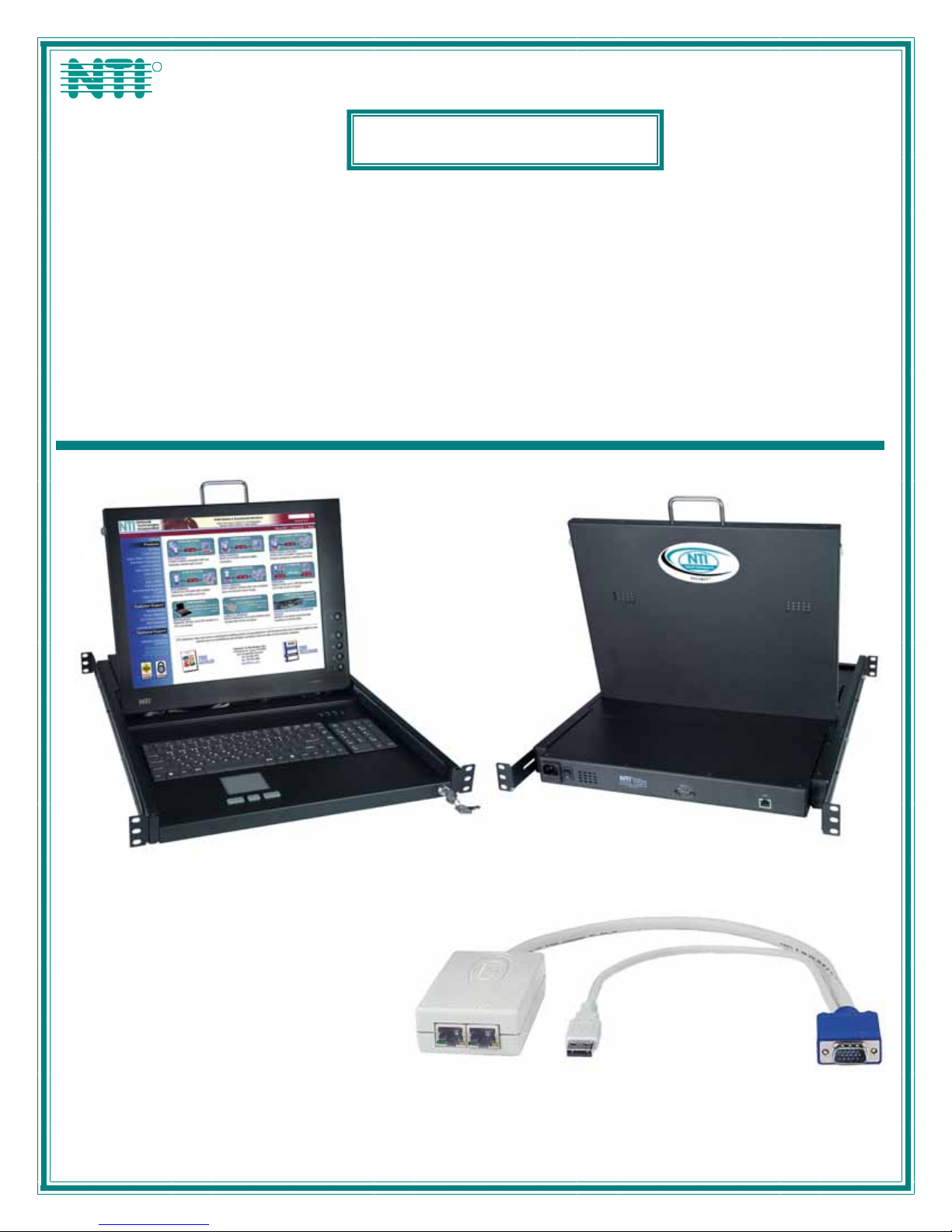
The RACKMUX-V15/17-N-PRIMUX is a KVM Drawer with KVM Switch via CAT5 (RACKMUX) that combines a rackmount 15" or
17” TFT/ LCD monitor, keyboard, touch pad, and KVM Switch via CAT5 (PRIMUX) in a space-saving 1RU industrial strength
drawer. The RACKMUX is equipped with a built-in switch function, which allows control of up to 64 SUN, PS/2, or USB-enabled
computers with a single keyboard, touchpad and monitor. When access to a server rack is needed, the drawer can be pulled out
and the display lifted up like a notebook computer, revealing the keyboard and touchpad. When the drawer is not in use, the
display can be folded forward and down so the 1RU drawer can be pushed into the cabinet easily and smoothly, helping to
organize and streamline busy server rooms.
The PRIMUX CAT5 KVM System allows the relocation of a VGA monitor, keyboard, and mouse from up to 64 PS/2, SUN, or USB
CPUs by as much as 1000 feet. The PRIMUX is comprised of one PRIMUX User Station (built into the RACKMUX) and at least
one Host Adapter (HA-PS2, HA-USB, or HA-SUN) connected to a CPU to be controlled by the user. This manual describes the
installation and use of both components.
The PRIMUX Host Adapter and User Station are interconnected with either CAT5 Unshielded Twisted Pair (UTP) or Shielded
Twisted Pair (STP) cable, CAT5e cable, or CAT6 cable.
The PRIMUX Series CAT5 KVM System is easy to install and has been thoroughly tested to insure reliable performance. Through
the use of CAT5, CAT5e, or CAT6 cable it is possible to economically increase the flexibility of a computer system.
Options
• LCD anti-glare protective glass shield - add a "G" to the model when ordering (i.e. RACKMUX-T15G)
• Telco 2-post style mounting kit- order RL-T15-TEL
RACKMUX Features
• Entire unit is only 1RU (1.75") high.
• High-quality metal construction (ideal for most industrial and commercial settings)
• 15" or 17" Rack Mount LCD Monitor features a wide viewing angle
• 1024X768 resolution for 15" XGA monitor
• 1280x1024 resolution for 17" SXGA monitor
• A forward-folding 15” or 17” TFT LCD with built-in OSD menu for screen adjustments
• Includes rack mount kit suitable for SUN and most EIA 19" racks
• Fits varying rack depths from 22” to 39” deep via adjustable mounting brackets
• VGA/SVGA/XGA/ SXGA Compatible
• Powered by 110-240VAC, 50 or 60Hz via IEC connector and country-specific line cord
• Auto shut-OFF switch: Turns OFF the power to the monitor when the LCD is in a folded-closed position.
• Standard 3-button touchpad
• Added security with a drawer lock to prevent unwanted access
• Locking rails to prevent movement of the drawer when fully extended
PRIMUX Features:
• Allows the placement of a monitor, keyboard, and mouse in a location where only these parts are needed without having
the CPU there too, taking up valuable space
• Allows any PS/2, USB, or SUN CPU to be accessed by a remote user (up to 1000 feet away)
• Additional RJ45 port on the Host Adapter allows the daisy-chaining of up to 64 Host Adapters providing user access to
up to 64 CPUs
• Control up to 64 CPUs from one keyboard, mouse, and monitor without "spaghetti" wiring
• Compatible with VGA, SVGA, XGA, and SXGA systems
• Provides crisp and clear resolution up to 1024x768 /60Hz @ 1000 feet (using CAT5 UTP cable - see pg 44 for details)
• Video quality adjustment is automatic providing optimum image quality
• Allows for future expansion- buy what is needed now, add more later as desired
Supported Operating Systems
The PRIMUX is compatible with:
• Win9x • WinMe • Solaris • Windows Server 2003
• WinNT • WinXP • MAC OS9.x , OSX • Others
• Win2K • Linux 7.x, 8.0 • Windows Server 2000
Options
• Telco 2-post style mounting kit- order RL-T15-TEL
1
Page 7
Materials
Materials Supplied with this kit:
• NTI RACKMUX-V15/17-N-PRIMUX
• Line cord, country specific
• Terminating Plug (for last Host Adapter in chain- see pages 9 and 11 for details)
• CD w/ Owner's Manual and Quick Start Guide (pdf files)
• Quick Start Guide (Printed)
Materials Not Supplied, but REQUIRED:
• NTI HA-PS2 PS/2 Host Adapter / HA-USB USB Host Adapter / HA-SUN Host Adapter (see pg. 5)
• CAT5/5e/6 unshielded twisted-pair cable(s) terminated with RJ45 connectors wired straight thru- pin 1 to pin 1, etc. (see pg.
45 for proper EIA/TIA 568B wiring method)
• A null modem cable will be required for future software updates (see specification on page 45).
Cables can be purchased from Network Technologies Inc by calling 800-RGB-TECH (800-742-8324) or (330)-562-7070 or by
visiting our website at www.networktechinc.com
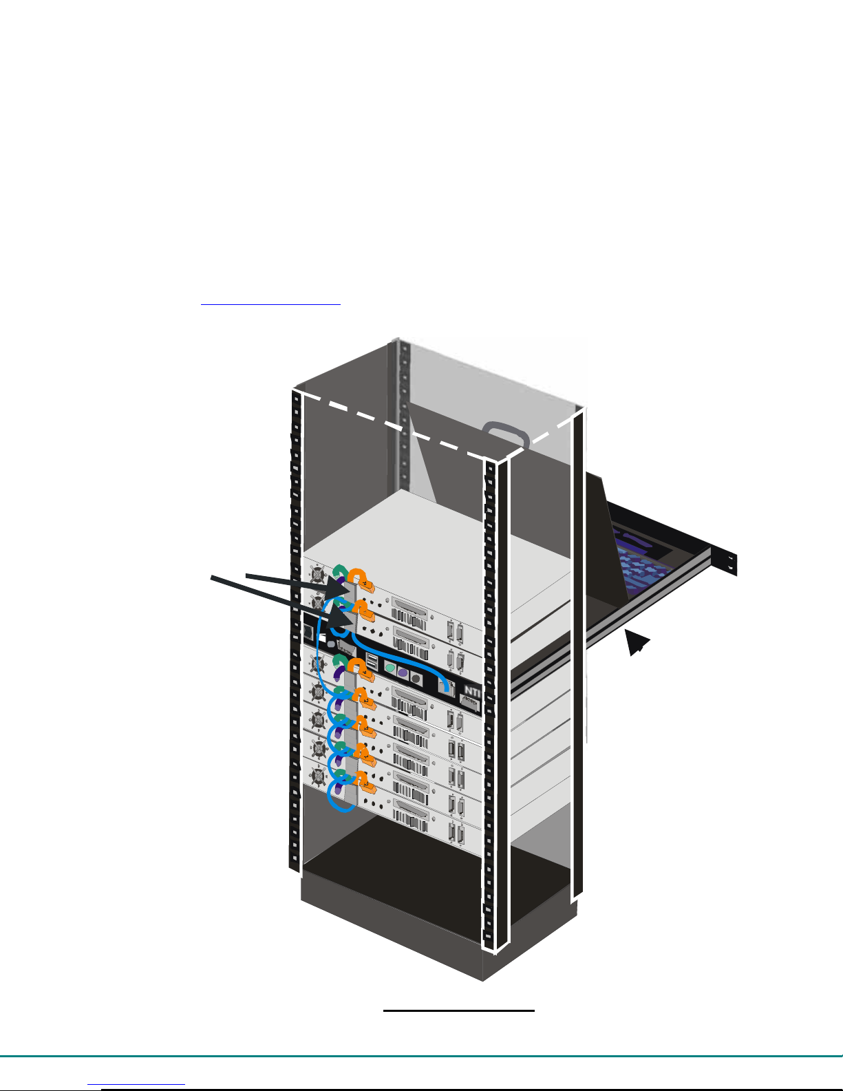
Server Rack
(Back View)
.
Host
Adapters
Daisy
Chained with
CAT5/5e/6
Cable
RACKMUX
KVM Drawer
wit h
PRIMUX
KVM Swit ch
Typical Application
2
Page 8
14
13
1
2
3
4
5
6
A
1
Front View
RACKMUX-V15-N-PRIMUX
12
11
10
7
8
9
15
17
16
Rear View
18
RACKMUX-V15-N-PRIMUX
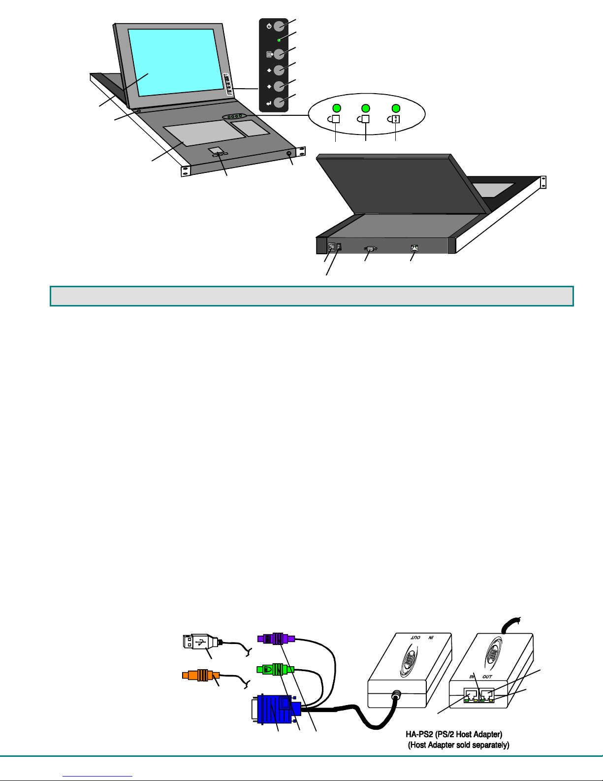
FEATURES AND FUNCTIONS
1. Power Button- press to turn the LCD monitor ON and OFF
2. Power LED- Indicates operation status
Green = Power-ON, Video Input Signal OK
Red = Suspend / Stand-by, or no Video Input Signal
3. Menu Button- press to turn ON the OSD menu
4. Up Arrow Button- press to move the cursor in the OSD menu up
5. Down Arrow Button- press to move the cursor in the OSD menu down
6. Select Button- press to select a menu item (when OSD menu is ON) or press to auto adjust the video quality (when OSD
menu is OFF)
7. NumLock LED- illuminates when the number lock is ON
8. CapsLock LED- illuminates when CapsLock is ON.
9. Scroll Lock LED- illuminates when the Scroll Lock keyboard feature is ON.
10. LCD Display- for viewing the video signal from the connected CPU
11. Auto Shut-OFF- switch automatically shuts OFF the LCD display when the monitor is folded down
12. 3-button touch pad- for controlling mouse movements on the monitor and controlling the computer
13. Keylock- to prevent unauthorized use of the RACKMUX
14. Keyboard- for manual data entry and computer control
15. IEC Connector w/Built-in 2A 240VAC Replaceable Fuse- for attachment of the IEC power cord to power the RACKMUX
drawer
16. Switch- for powering ON and OFF the RACKMUX drawer
17. RS232- DB9 male- serial communication port for updating firmware
18. Cat5 - RJ45 female- for connection of CAT5 cable between Host Adapter and User Station
18a. Yellow LED- power indicator- illuminates when power has been supplied to the unit
18b. Green LED- traffic indicator- illuminates when there is communication between the User Station and Host Adapters.
19. Video Connector- blue 15HD male- for connecting to the video port on the CPU
20. Mouse Connector- green male 6 miniDIN (HA-PS2 only)- for connecting to the mouse port on a PS2 CPU
21. Keyboard Connector- purple male 6 miniDIN (HA-PS2 only)- for connecting to the keyboard port on a PS2 CPU
21a. Device Connector- male USB Type A (HA-USB only)- for connecting to a device port on a USB CPU
21b. Device Connector- orange male 8 miniDIN (HA-SUN only) - for connecting to the device port on a SUN CPU
22. Cat5- RJ45 female- for connection of CAT5 cable between daisy-chained Host Adapters
21a
21b
19
20
21
(Front View)
22
18b
(Rear View)
18
18a
3
Page 9

PREPARATION FOR INSTALLATION
• The CAT5 cables must be run between the locations where the Host Adapter will be connected and RACKMUX is positioned.
Be careful to route the cables away from any sources of magnetic fields or electrical interference that might reduce the quality
of the signal (i.e. AC motors, welding equipment, etc.) .
NOTE: The installer must ensure that all CAT5 cable between the Host Adapter and PRIMUX and between each Host
Adapter (if more than one) is of the straight-through type and not
• A 120V or 240V electrical supply (depending on the cord being used) must be provided close enough to the position of the
RACKMUX to plug the power cord into.
• All cables should be installed such that they do not cause stress on their connections to the equipment. Extended lengths of
cable hanging from a connection may interfere with the quality of that connection. Secure cables as needed to minimize
this.
• Properly shut down and disconnect the power from the CPU and devices to be extended. If other equipment is involved
whose connections are being interrupted, be sure to refer to the instruction manuals for that equipment for proper
disconnection and re-connection procedures before proceeding.
crossed.
Definitions
Segment A single or series of CAT5 cable(s) from one User Station to one or more Host Adapter(s)
that are daisy-chained together. A segment begins with the User Station and ends with the
last Host Adapter in the daisy chain.
Master
Authority
Master ID A number automatically assigned by the User Station to a PRIMUX segment. It is used to
String A set of characters, A-Z, 0-9, upper or lower case
Integer Any whole number (1,2,3…)
Unique ID Number identifying a Host Adapter to the master authority of a segment.
The ultimate controlling authority in a segment (i.e. the master authority establishes the
unique I.D. for each Host Adapter). The master authority is part of the User Station.
identify Host Adapters that have been configured by the master authority, particularly Host
Adapters that attempt to join the segment. The Master ID is used to distinguish between
different User Stations and their segment Host Adapters.
4
Page 10
s
INSTALLATION
Rack Mounting Instructions
The RACKMUX was designed to be mounted to a rack and includes mounting flanges to make attachment easy.
1. Determine the mounting height in the rack for the drawer. It should be a height comfortable to use the keyboard and see the
LCD display. Mark holes in each of the 4 corner cabinet rails at points all level with each other.
2. Secure the rear brackets to the rear rack cabinet rails. Apply the top screws (supplied) for each bracket to the holes marked in
step 1.
3. Lift the keyboard into position and line the studs on the left and right sides up with the slotted openings in the rear bracket.
Apply the nuts (supplied) to the studs but do not tighten the nuts yet.
FYI: There are 4 mounting studs provided on each side of the RACKMUX. Depending on the depth of the rack and
distance apart of the cabinet rails, the position of the rear bracket may make all 4 studs available for use. In this case,
apply the 2 nuts to the studs furthest apart from each other on each side.
4. Slide the drawer in until the top holes in the front bracket flanges line up with the holes marked in step 1. Secure the front
brackets on the drawer to the front cabinet rails with two screws per bracket. Be sure to tighten the screws securely. Then
tighten the nuts applied in step 3.
5. Apply one more screw to each of the rear brackets to finish.
Front bracke t
flange on drawer
Secure bracket
to rail using two
screws and nuts
(supplied)
Figure 1- Mount RACKMUX to rack
Note: To provide sufficient room for the LCD monitor to be opened to a proper viewing angle (a minimum 90 degree
position from the keyboard), ensure that all devices mounted above the RACKMUX extend no more than 1.75” from the
rack frame. (See Fig. 2)
Figure 2- Position RACKMUX with clearance to open
Front Cabinet
Rail
Drawer
Stud on drawer
Rear bracket overlapping
draw er
(Rear edge
of drawer)
Apply nuts (supplied) to studs and
secure rear brackets to drawer.
"X" must be
less than 1.75"
for LCD to open
to full 90
X
90
Side View of RACKMUX-T15
Rear Cabinet
Rail
Rear bracket
flange
Secure bracket
to rail using two
screws and nut
(supplied)
Server mounted
above RACKMUX
in the same rack
5
Page 11
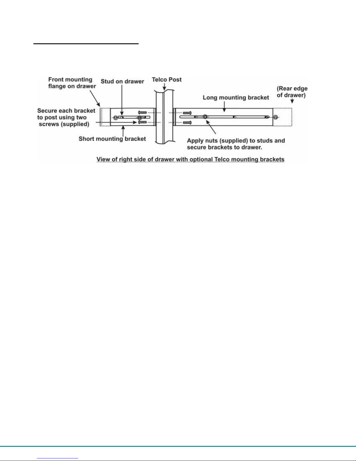
Optional Telco 2-Post Mounting
If the Telco 2-post mounting bracket kit (RL-T15-TEL) is to be used, secure the short and long brackets to each side of the drawer
as shown in Fig. 3. Apply 2 nuts (supplied) per bracket to secure the brackets to the drawer. Apply two #10-32x3/4” screws
(supplied) per bracket to the post at the desired height. Slots are provided in the brackets to make minor depth adjustments
easy. Be sure to properly tighten all nuts and screws before using the drawer.
Figure 3- Mount to Telco post with optional mounting brackets
6
Page 12
The Host Adapter
The PRIMUX HA Host Adapter is designed to support PS/2, SUN, and USB CPUs. For PS/2 CPUs use HA-PS2, for SUN CPUs
use HA-SUN, and for USB CPUs use HA-USB. Host Adapters may be connected to or removed from a CPU without powering
down the CPU, provided the CPU and operating system supports device hot plugging. (Operating systems known to support hotplugging include Windows 2000 SP3 and higher, Windows XP, and Linux 2.6 and higher. )
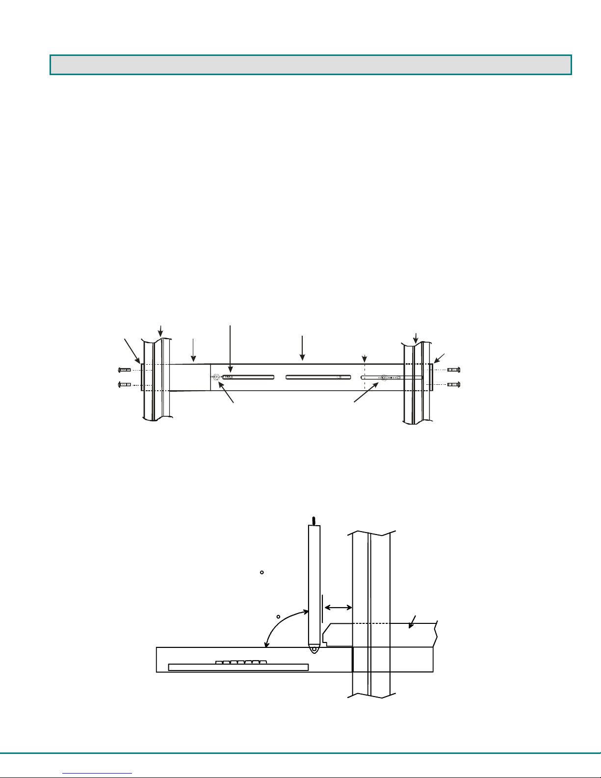
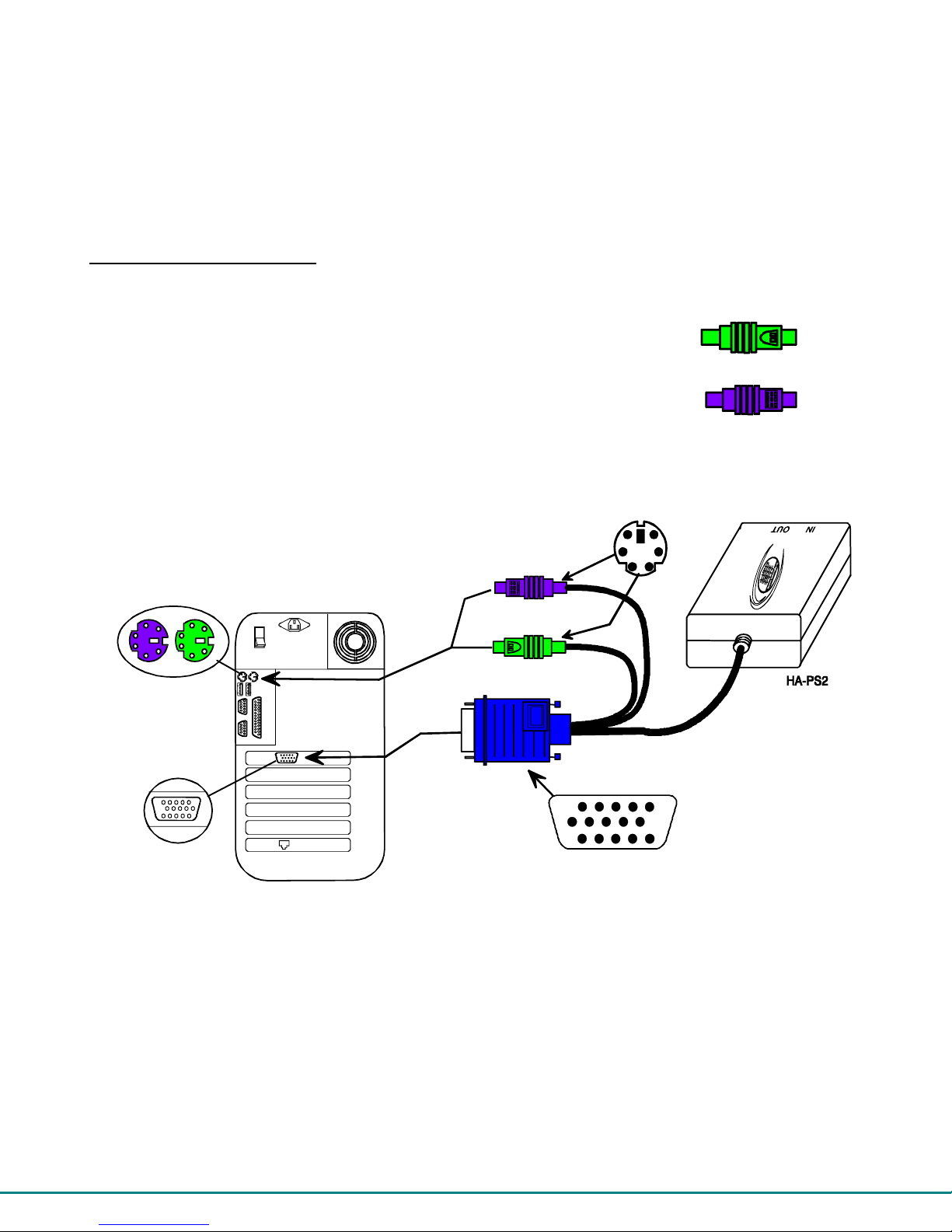
Installation of a PS/2 CPU
Plug the cables of the HA-PS2 Host Adapter into the back of the CPU after disconnecting the power cord from the CPU.
(See Figure 4.)
a) Connect the green 6 pin miniDIN cable end with the mouse symbol
on it to the mouse port on the back of the CPU.
b) Connect the purple 6 pin miniDIN cable end with the keyboard symbol
on it to the keyboard port on the back of the CPU.
c) Connect the blue 15HD cable end to the VGA port on the back of the CPU.
6 pin miniDIN
female connectors
Figure 4- Connect a HA-PS2 Host Adapter to a PS/2 CPU
15HD female
video connector
Rear View of PS/2 CPU
purple-keyboard
green-mouse
15HD male
video connector
6 miniDIN
male connectors
PS/2 Mouse
PS/2 Keyboard
(Front View)
7
Page 13
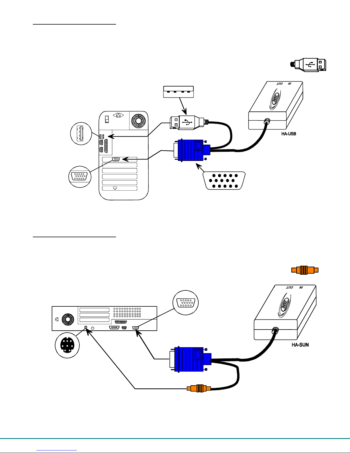
Installation of a USB CPU
Plug the cables of the HA-USB Host Adapter into the back of the CPU after disconnecting the power cord from the CPU.
(See Figure 5.)
a) Connect the cable with the USB Type A male cable end on it to a USB Type A female port on the back of the
CPU.
b) Connect the blue 15HD cable end to the video connector on the back of the CPU.
USB Type A
device port
15HD female
video connector
Rear View of USB CPU
Figure 5- Connect a HA-USB Host Adapter to a USB CPU
USB Type A male
15HD male
video connector
(Front View)
USB Devices
Installation of a SUN CPU
Plug the cables of the HA-SUN Host Adapter into the back of the CPU after disconnecting the power cord from the CPU.
(See Figure 6.)
a) Connect the orange 8 pin miniDIN cable end on it to the devices port on the back of the CPU.
b) Connect the blue 15HD cable end to the VGA port on the back of the CPU.
8 pin miniDIN
female connector
Figure 6- Connect a HA-SUN Host Adapter to a SUN CPU
FYI: The HA-SUN Host Adapter does not provide keyboard power-ON support for legacy SUN CPUs.
Rear View of SUN CPU
15HD female
video connector
orange-devices
8
SUN Devices
(Front View)
Page 14
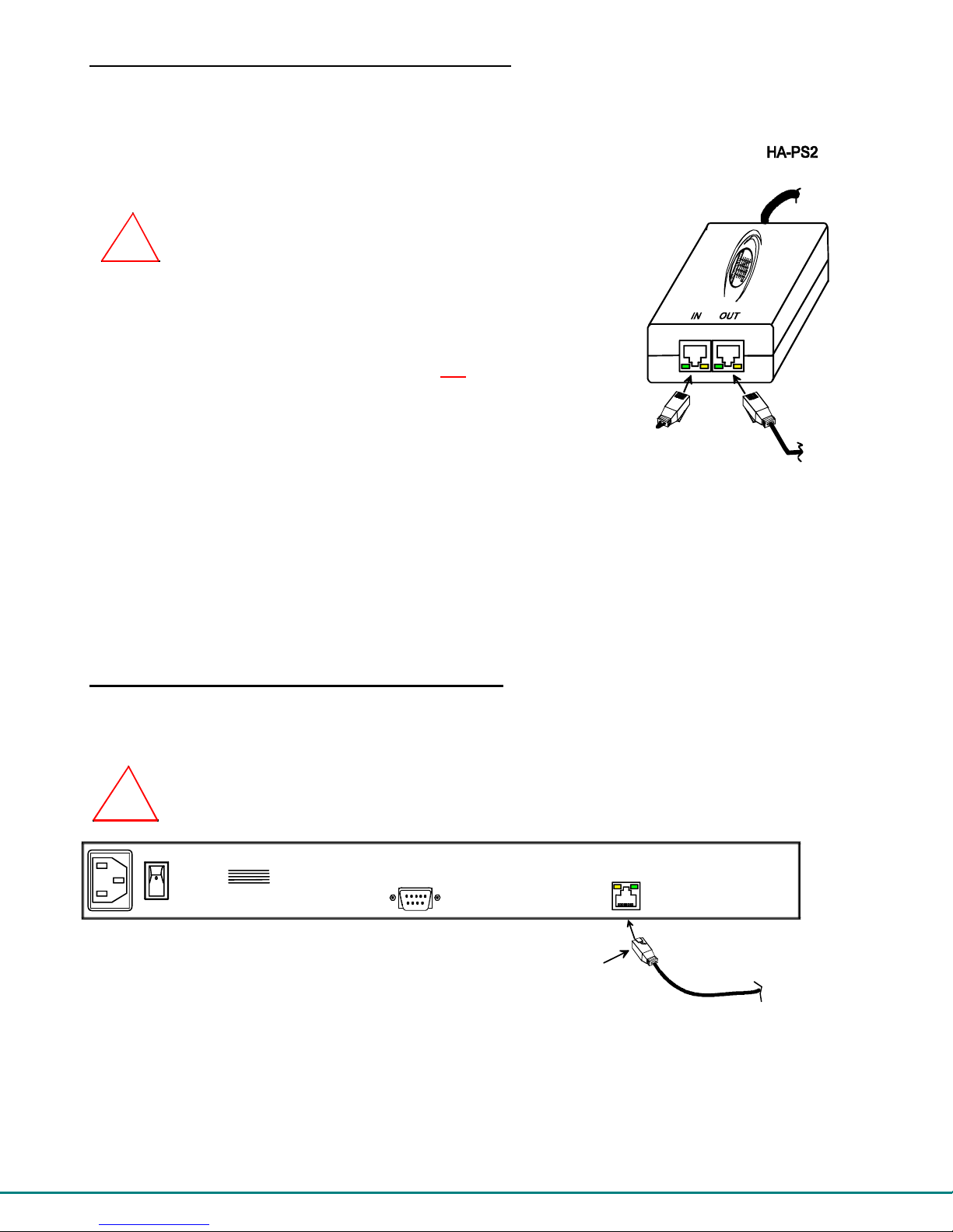
Connecting the CAT5 cable to the Host Adapter
Connect CAT5 cable to the “OUT” port on the Host Adapter. (See Figure 7.) When properly inserted the cable end should snap
into place. Also be sure to insert the Terminating Plug into the "IN" port on the Host Adapter if this is the only Host Adapter in the
segment. Otherwise, see "Daisy-Chained Host Adapters" on page 9 to add more Host Adapters to the segment.
NOTE: If an RJ45 wall outlet is being used, connect the other end of the extension cable
to the RJ45 wall outlet.
!
WARNING: Never connect the PRIMUX Host Adapter to an Ethernet card,
Ethernet router, hub or switch or other Ethernet RJ45 connector of an Ethernet
device. Damage to devices connected to the Ethernet may result.
NOTE: The installer must ensure that all CAT5 cable between the Host Adapter
and User Station is of the straight-through type and not
Figure 7- Connect CAT5 cable to Host Adapter
crossed.
Terminating
Plug (Supplied)
(Rear View)
Cable to CPU
CAT5 Cable
to User Station
The User Station
Connecting the CAT5 cable to the User Station
Make sure the CAT5 cable has been installed in accordance with the “Preparation for Installation” instructions on page 4.
Connect the CAT5 cable to the “Cat 5” port on the User Station. (See Figure 8.) When properly inserted the CAT5 cable end
should snap into place.
WARNING: Never connect the PRIMUX User Station to an Ethernet card, Ethernet router, hub or switch
or other Ethernet RJ45 connector of an Ethernet device. Damage to devices connected to the Ethernet may
!
result.
Figure 8- Connect CAT5 cable to User Station
NOTE: If an RJ45 wall outlet is being used, connect the other end of the extension cable to the RJ45 wall outlet.
NTI
1275 Danner Dr
Aurora, OH 44202
www.networktechinc.com
NETWORK
TECHNOLOGIES
INCORPORATED
Tel:330-562-7070
Fax:330-562-1999
REAR VIEW OF RACKMUX-V15-N-PRIMUX
RS232
CAT5
RJ45 male
CAT5 connector
CAT5 cable
to first Host Adapter
in the segment
9
Page 15
Power Up for the first time
Note: The CAT5 cable should already be connected before powering up the RACKMUX.
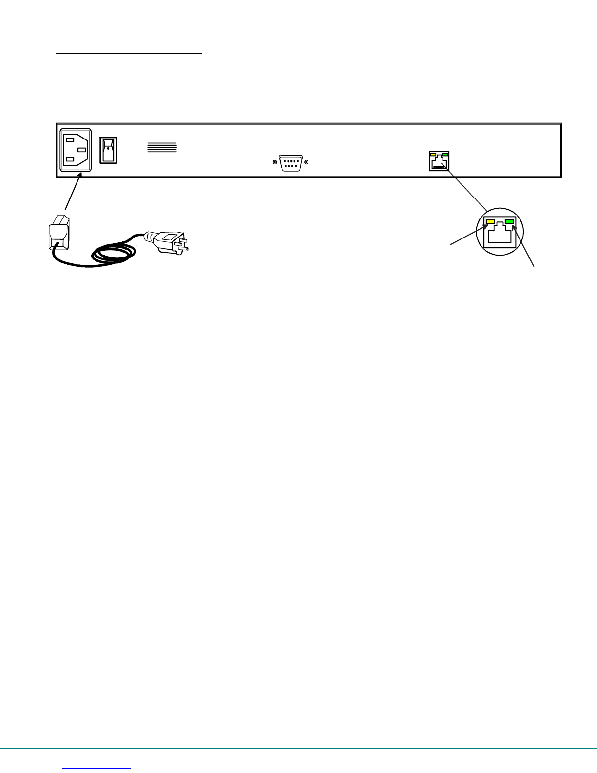
1. Connect the IEC power cord to the IEC connector on the RACKMUX (see Figure 9).
IEC Powercord
NTI
1275 Danner Dr
Aurora, OH 44202
NETWORK
TECHNOLOGIES
INCORPORATED
Tel:330-562-7070
Fax:330-562-1999
www.netw orktechinc.co m
Figure 9- Connect the power cord to the RACKMUX
2. Using the key, unlock the drawer and slide the keyboard and LCD Display out far enough to raise the display to a
comfortable viewing angle.
3. Power ON the RACKMUX with the power switch at the rear of the unit.
4. Power ON the KVM Drawer with the power switch located on the monitor.
5. Adjust the screen's brightness and contrast with the controls also located on the monitor– as needed.
6. Power ON any attached CPUs. The yellow LED on the RJ45 connector of the User Station should illuminate, indicating
that a proper power connection has been made to it.
FYI: The Host Adapter is powered by the CPU.
7. With the User Station and Host Adapter connected via CAT5 cable, refer to "Using the PRIMUX CAT5 KVM Switch" on
page 13.
FYI: The green LED on each RJ45 connector will illuminate anytime data traffic is passing between the Host Adapter and
User Station, indicating proper CAT5 cable connection and communication. (See Figure 9)
REAR VIEW OF RACKMUX-V15-N-PRIMUX
RS232
Yellow Power LED
CAT5
Green Communication LED
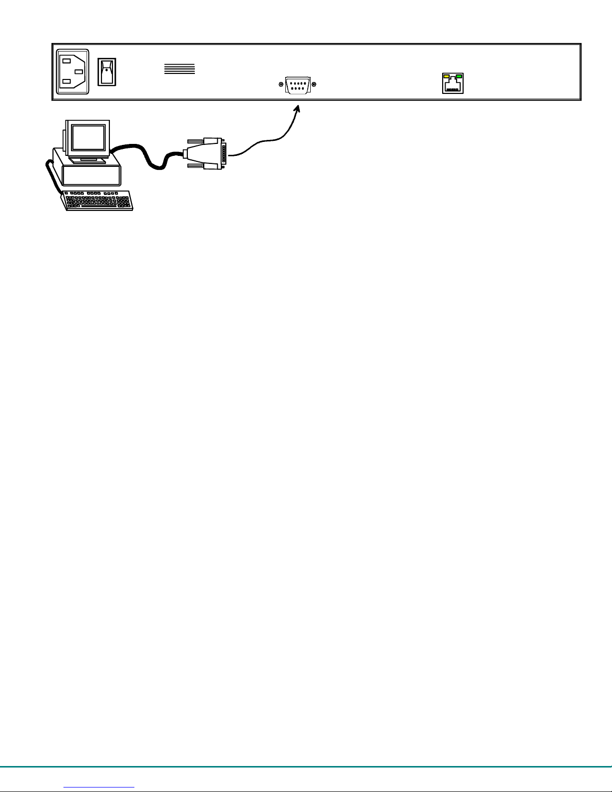
Connection for Firmware Update
The firmware in the PRIMUX can be updated as new firmware becomes available. To perform an update, a null modem cable
(see pinout on page 45) or NTI DINT-xx-FF (xx- 6,10, or 15 feet long) cable must be connected between a terminal (PC) and the
“RS232” port on the RACKMUX. Instruction for performing the upgrade can be found on page 35.
10
Page 16
NTI
1275 Danner Dr
Aurora, OH 44202
NETWORK
TECHNOLOGIES
INCORPORATED
Tel:330-562-7070
Fax:330-562-1999
www.networktechinc.com
VGA
Multi-Scan
Monitor
Null modem cable
Terminal
Figure 10- Connect a Terminal (PC) to perform firmware update
REAR VIEW OF RACKMUX-V15-N-PRIMUX
RS232
CAT5
11
Page 17

Daisy-Chained Host Adapters
Up to 64 Host Adapters can be connected in a daisy-chain to create a segment of CPUs that are controlled by a single user from a
User Station. The first Host Adapter is connected to the User Station via the "OUT" port. The additional Host Adapters in the
segment will have CAT5 cable going from their "OUT" port to another Host Adapter's "IN" port to enable communications between
the user and each CPU in the system, as shown in Figure 11. A Terminating Plug must be installed in the "IN" port of the last
Host Adapter in the segment.
NOTE: The installer must ensure that all CAT5 cable terminations between each Host Adapter are of the straight-through
type (pin 1 to pin 1, pin 2 to pin 2, etc.) and not
NOTE: The total length of the CAT5 cable from the User Station to the last Host Adapter in the daisy-chain must not
exceed 1000'.
Last Host
Adapter in
the segment
(Rear View)
Cable to CPU 64
Terminating
Plug (Supplied)
CAT5 Cable
CAT5 Cable
Figure 11- Daisy-chained Host Adapters
crossover.
(Rear View)
CAT5 Cable
Cable to CPU 3
(Rear View)
CAT5 Cable
Cable to CPU 2
(Rear View)
CAT5 Cable
to User Station
Cable to CPU 1
Adding a Host Adapter to the segment
When adding a Host Adapter to a segment, whether at the end, or inside the chain (between two other Host Adapters connected
together), the administrator must follow some simple steps:
1. Make sure the Host Adapter being connected to a CPU is the proper type for the CPU.
CPU TYPE HOST ADAPTER MODEL
PS/2 HA-PS2
USB HA-USB
SUN HA-SUN
2. Determine what name the Host Adapter will be identified as in the Host Adapter list (should be unique to all other known hosts
in the segment).
3. Follow the installation instruction on page 7 for Host Adapters and above for Daisy-Chained Host Adapters.
FYI: A Host Adapter can be added to the last Host Adapter in the chain, or between two existing Host Adapters.
4. Once the installation procedure is complete the connected CPU must be powered ON.
Note: The connected CPU must be powered ON at least once in order for the Host Adapter to be identified and registered
by the User Station as indicated in the Command Mode OSD list (see page 17).
5. This Host Adapter will be auto discovered by the master authority. If the Host Adapter is new (unused), it will identify itself as
"(NEW PS2 HA)" , "(NEW USB HA)", or "(NEW SUN HA)".
Note: If the Host Adapter has been previously used, it will still have the name it was issued. To reset the Host Adapter
to factory settings, the administrator must use “Reset Host Data” (page 27).
6. The administrator should assign a unique name to the Host Adapter (see page 27)
7. All users will have default access to the new Host Adapter unless the Administrator configures the access otherwise (see
page 29).
8. Once access controls have been set, the administrator should verify the security access to the new Host Adapter.
12
Page 18

USING THE PRIMUX CAT5 KVM SWITCH
The PRIMUX CAT5 KVM System is designed to enable a user to control as many as 64 PS/2, USB, and SUN CPUs (any mixture
of each) from a single User Station as much as 1000 feet from the farthest CPU. Control is achieved through the use of On
Screen Display (OSD) Menus. Access to one or more CPUs is determined by the security configuration of the PRIMUX as set by
the administrator. Once user access limitations are defined, the user can select which CPU to connect to using the OSD menu.
Hot Plugging
The PRIMUX Host Adapter may be hot-plugged to a CPU at any time without causing a CPU error, provided the CPU and the
operating system supports device hot-plugging. (Operating systems known to support hot-plugging include Windows 2000 SP3
and higher, Windows XP, and Linux 2.6 and higher, Windows Server 2000 and 2003.)
Note: When hotplugging the mouse and keyboard cables into a PS/2 CPU, be sure to connect the mouse cable first, then
the keyboard cable. Failure to connect in this order may cause the mouse to not be recognized by the CPU.
CAT5 cables can be hot plugged. If the CAT5 cable is disconnected, the User Station will continue to monitor all Host Adapters
in the Host Adapter List.
FYI: Once a Host Adapter is selected by the User Station it will stay connected or attempt to connect forever if the
selected Host Adapter is powered OFF or the CAT5 cable is disconnected. To properly remove a Host Adapter, the user
must delete it from the Host Adapter List (page 27).
Hot plugging a Host Adapter to an NTI VOPEX splitter is not recommended. If communication is lost, send a "Reset Host"
command (page 27) from the User Station to restore communication.
Initial Startup
After installing the User Station and one or more Host Adapters as described under “Installation” beginning on page 5, when first
applying power the user named “
default, access is given to all Host Adapters and their connected CPUs, and Scan Mode will scan all connected CPUs.
User Rights vs. Administrator Rights
Before continuing, the user should consider what action is going to be taken. The Administrator has full control over the
functions of the PRIMUX CAT5 KVM system, while the User has limited control.
Administrator Rights Include:
¾ Change the Administrator Password
¾ Assign, edit, and remove user names and passwords
¾ Define user access rights to CPUs in the segment
¾ Adding and configuring Host Adapters in the segment
¾ Configure operating parameters of the User Station
¾ Update DDC information between the monitor and CPUs
¾ The ability to connect the Userstation’s keyboard, mouse, and monitor to any CPU
¾ The ability to enable/disable Scan Mode
¾ The ability to change the sorting method of Host Adapters by index number or alphabetically
FYI: Users can be given full administrative access rights by the administrator.
User Rights Include
¾ The ability to connect the Users Station’s keyboard, mouse, and monitor to CPUs (only those CPUs that have been
granted access by the administrator).
¾ The ability to enable/disable Scan Mode
¾ The ability to change the sorting method of Host Adapters by index number or alphabetically
:
NEWUSER1” will be automatically logged-in and the Command Mode menu will appear. By
Administrator Login and Password
To login as the administrator, press <L> to logout as NEWUSER1 and the login splash screen will appear. While holding down
the <Shift> key, enter an administrator name and default password:
administrator names = <ROOT> or <ADMINISTRATOR> (either can be used)
administrator password = <NTI>
Note: User names and passwords are case sensitive.
13
Page 19

With a successful login, the administrator can setup additional users (see page 28).
FYI: The User Station can be configured to Autologon a specific user (page 33) with each User Station power up or have
a Login splash screen appear for the user to login to the User Station. The administrator can also configure the User
Station to autoconnect a user to a specific Host Adapter at logon by configuring the Logon Host and Action on Logon in
the Edit User menu (page 29). For more on setting up users, see page 29.
Setup Host Adapter(s)
No initial configuration of the Host Adapter is required for it to be identified by the User Station in the segment. Once discovered,
it appears in the segment, and the Master Authority assigns the Host Adapter its Unique ID value. This value is used to
¾ set its identity for the security allow/deny access attribute (page 29)
¾ set its identity in the list of Host Adapters/CPUs that can be scanned in Scan Mode (page 22)
¾ select the order of Host Adapters in numeric mode
Note: In order for the User Station to identify a Host Adapter and include a CPU in the OSD list of CPUs connected (page
17) , the CPU must be powered-ON at least once. After the first powered-ON connection, the User Station will indicate
the status of the connected CPU, whether it is powered-ON or not. .
Note: Any configuration changes made to the Host Adapter must be made and saved while the connected CPU is
powered-ON.
The Unique ID is stored in the Host Adapter and saved there, even if power is removed.
Quick Connect
From the Command Mode menu, to make connection to any Host Adapter in the segment,
press <G> followed by the index number (see page 17) of the desired Host Adapter,
press <Enter> to select it,
press <Enter> again to connect to it.
-OR-
use the mouse to highlight the desired Host Adapter to connect to and click on it to connect.
Press <X> or <Esc> to exit Command Mode and use the connected CPU connected to the selected Host Adapter.
Press <Ctrl> + <`> to return to Command Mode (see page 17).
Change the Default Administrator Password
Once the administrator is logged in, it is recommended that the the administrator change the default administrator password.
To change the administrator password:
- Press A (Administration Menu) - E (Edit Menu) - U (Edit User Menu) - P (Change Root Password)
- Enter the current password (default is "NTI")
- Enter the new password (case sensitive, 16 characters maximum, alphanumerc)
- Press <Enter>
- Re-enter to confirm the new password
- Press <Enter> to finish, or <Tab> to enter the password again.
Note: In the event the password is forgotten, contact NTI for instruction on how to reset the password to the default
"NTI".
FYI: When the password is changed for user ROOT , it automatically changes for user ADMINISTRATOR as well.
Note: User names and passwords are case sensitive.
14
Page 20

Standards of Operation
Throughout this manual, various standards of operation apply to the menus used to control and operate the PRIMUX.
• OSD menus can be navigated using the mouse, the up and down arrows on the keyboard, and the <Page Up>, <Page
Down>, <Home>,<Tab> and <End> keys.
- The up and down arrows increment/decrement one line item at a time
- <Page Up> and <Page Down> increment/decrement by one page at a time
- <Home> will jump to the beginning of the list
- <Tab> will jump between selectable fields (on supported screens)
- <End> will jump to the end of the list.
• Alphabetic and numeric characters can be typed in the OSD menu fields, as well as these additional characters:
! (exclamation point) , * (asterisk) , ( , ) (left and right parenthesis), - (dash) , _ (underscore), + (plus sign) , = (equal
sign) , ; (semicolon) , : (colon), “ (quotation mark) , ‘ (apostrophe) , ? (question mark) , / (forward slash) , comma, and
period .
• The scroll bar in a list can be used by clicking on the corresponding up and down arrow above and below the scroll
bar.
• The mouse wheel may be used to move the selection bar
• The <Shift> key must be used to enter an uppercase letter within all OSD menus.
• Functions that are "Administrator Only" are also available to users having administrative rights (see page 29).
• Placing the mouse over a listed Host Adapter highlighting the listed item with a blackened background "selects" the
Host Adapter. Clicking on it while in Command Mode will connect to that Host Adapter.
• Available functions will have white characters with one red character. The red character indicates what
corresponding keyboard character is associated with that function. The background of available functions will
become green when the mouse pointer is positioned over the function. Functions that are not available will be
transparent.
• When selecting a function spelled with a red letter, press the keyboard key corresponding with that letter on the
keyboard or use the mouse to select the function. Red letter keys are NOT case sensitive.
• When "+" is shown between keystrokes, it indicates a chorded sequence (press and hold the keys consecutively
until all keys in the sequence are pressed). I.e. <Ctrl>+<`> is a chorded sequence to enter Command Mode.
• When "-" is shown between keystrokes, it indicates to press the keys consecutively (press and release one at a time)
• To exit (and step back 1 menu) from any menu, press <Esc> or <X> on the keyboard or click on "Esc" in the menu.
• Press <F10> to return directly to the Command Mode menu
• Alphabetic Keys pressed to navigate OSD menus can be upper or lowercase.
15
Page 21

Security
The PRIMUX CAT5 KVM System is designed with security to prevent unauthorized use of the CPUs connected as determined by
the administrator. Up to 16 users may be given access to the system, each with individual limitations of use. Only the
administrator or user with administrative privileges can activate or deactivate the security features on each user port. Finally, the
administrator can set a maximum idle time value after which the current user will be logged out and the login splash screen
displayed again. The current security status, idle time out, and scan dwell time are all saved and will be restored whenever
power to the User Station is cycled OFF, then ON. To reset the administrator’s password, call NTI and have the device serial
number of the PRIMUX User Station available.
Autologin
By default, the user account “NEWUSER1” has been configured to automatically login at power-up. The adminstrator may
reconfigure the User Station to autologin a different user (page 33) or have a Login splash screen appear at power-up requiring a
user to login, with or without a password. The autologin user uses CPUs listed in its Host Allow/Deny Access List as configured
by the administrator (page 29). The autologin user can be configured to automatically connect to a CPU, or open the Command
Mode menu.
Administrator Login
To access the OSD menu Command Mode from the keyboard press the <Ctrl> + <`> (accent/tilde key). (An additional alternate
OSD key may be defined, see page 34.) Press <L> to logout as a user. The User Login screen will automatically appear on the
monitor. In order to configure the PRIMUX (the PRIMUX must be powered ON), the administrator must login with a proper user
name and password. While holding down the <Shift> key, enter the following;
administrator names = <ROOT> or <ADMINISTRATOR> (either can be used)
administrator password = <NTI>
FYI: The names for the administrator (“ROOT” and “ADMINISTRATOR” ) cannot be changed.
Note: User names and passwords are case sensitive.
Once logged-in, follow the instructions on pages 32 or 27 for changing the password. Once the password is setup, if it is lost or
forgotten the administrator will have to contact NTI for assistance on clearing the password and set it up again. The administrator
can setup each of the users (page 30) and the limitations of their use of the individual CPUs from within Administration Mode.
User Login
The administrator may configure the User Station to require each user to login using a predefined password to gain access rights
to CPUs and to the features in the OSD menus. Once logged in, the user may be directed to either a specific CPU (provided the
CPU is powered ON), or to the OSD menu where the user can decide what action is to be taken. The initial action (Action on
Logon- page 29) and whether or not to connect to a specific Host Adapter (Logon Host- page 29) will be configured by the
administrator.
Once logged-in, a user can use the Command Mode functions described below and on page 17 to control the segment of CPUs
within the limitations as determined by the administrator.
Function Keystroke
Add a character to the user
name/password
Remove previous character from
the user name/password
Tabs to the next field
Submit user name/password/data
If the password submitted is incorrect, the user will
not be able to proceed.
If the password submitted is correct, the user will
either proceed to a CPU chosen by the
administrator and operate in Normal Mode, or
proceed to the Command Mode menu.
Figure 12- Login splash screen
A-Z, 0-9
Max. 16 characters
Backspace
Tab
Enter
16
Page 22

e
Adapter
User Access Functions
Command Mode
In order to control the User Station with the keyboard, Command Mode must be enabled. To enable Command Mode from the
keyboard:
Press
All the status lights on the keyboard will illuminate to indicate that Command Mode is enabled. At this point, the Command Mode
menu will be displayed.
The Command Mode menu (see Fig. 13) lists all Host Adapters by name and index number. Only 8 Host Adapters are listed on
the screen at a time. To view the other portions of the list, scroll using the arrow keys on the keyboard or use the mouse to click
on the arrows on the scroll bar in the OSD menu. When the Command Mode main menu is first displayed, the first Host Adapter
listed will be the Host Adapter the current user is connected to, followed by the next seven consecutively numbered ports.
(Alternatively the list may be sorted alphabetically- see Settings Menu on page 19 to toggle sort method.) The names of
accessible Host Adapters are displayed with white characters. The access rights for the user logged-in may not include all Host
Adapters. Names of restricted access Host Adapters are displayed in blue.
An arrow to the left of an index number in the list indicates the Host Adapter the user is currently connected to. From left to right,
the columns display the following:
• Index Number
• Host Adapter Name
• Type of Host Adapter connected (PS2, SUN, or USB)
• CPU power status (where "p" means ON and "
FYI: A red hourglass will appear
near the upper right corner of the
OSD menu to indicate that the
screen is being refreshed. This
will occur after 5 seconds of
keyboard and mouse inactivity..
Arrow indicates currently
connected Host Adapter
Commands for submenus
Figure 13- Command Mode main menu
The list below describes the command functions available from the keyboard within the OSD mode of control after entering into
Command Mode:
Function Keystroke
Select the previous Host Adapter
Select the next Host Adapter
Decreases the menu by 1 page (displays the previous 7 Host Adapters)
Increases the menu by 1 page (displays the next 7 Host Adapters)
Ctrl
Index Number
Host Adapter Name
Logged-in user
+
(ACCENT/TILDE
~
`
`
KEY)
- " means OFF)
Selection Bar
The CPU connected to a Host Adapter must be
powered-ON at least once while connected to the
segment and powered-ON User Station in order to
be included in the Command Mode list of CPUs.
Type of Host
Up Arrow
Down Arrow
Page Up
Page Down
CPU Power
Status
Mouse Cursor
Mouse
Controls
Home
Page Up
Up One
Down On
Page Down
End
Display first 8 Host Adapters and move selection bar to the first
Display last 8 Host Adapters and move selection bar to the last
Press to toggle enable/disable Scan Mode
Home
End
S
17
Page 23

Function Keystroke
Enter Settings Menu
Search- locate a Host Adapter (using name, comment, unique ID, index
number)
Enter Administration Mode (Administrator only- see page 25)
Display info for the selected Host Adapter/User Station
Display Command Mode Help Menu
Go to - select Host Adapter by index number
Find- select Host Adapter by name
Connect to the highlighted Host Adapter
T
R
A
I
H or F1
G
F
Enter or
Spacebar
Log Out the User/Administrator and disconnect from the Host Adapter
L
(The login screen will appear)
Exit Command Mode without logging out
X or Esc
The mouse can also be used to control the User Station Command Mode.
• The scroll wheel can be used to scroll through the Host Adapters list.
• The mouse cursor can be moved to the any of the command fields where the user can click on
the left mouse button to select that function.
• Host Adapters listed on the screen can be selected by moving the cursor onto a Host Adapter.
• To connect to a Host Adapter, click on the selected Host Adapter.
• To move through the Host Adapter list, the scroll bar to the right of the list can be used by clicking the up and
down arrows.
Note: Exit Command Mode to enter Normal Mode and control the connected CPU. To exit Command Mode, press <Esc>
<X> or click the “ESC” command on the screen with the mouse.
Scan Mode
To activate Scan Mode press <S> from the Command Mode menu.
Scan Mode enables the user to scan through selected Host Adapters (whether they are powered-ON or OFF) and to have full
device control of the connected powered-ON Host Adapter. From the Settings menu (page 19) the user can edit the list of Host
Adapters that can be scanned. A Host Adapter is skipped from the scan cycle if one of the following conditions is true:
• the Host Adapter is not in the scan list
• the user does not have access rights to the Host Adapter
When switching to a new Host Adapter the Host Adapter name is displayed by OSD for 5 seconds or until a key is pressed or the
mouse is moved, whichever comes first. The scan dwell time is programmable from 2 to 255 seconds (default time-out period is 5
seconds). When the user moves the mouse or types on the keyboard the scanned Host Adapter becomes active and scanning is
stopped. The switch will resume scanning after a period of user inactivity determined by the scan dwell time. See Settings Menu
below for configuring the scan dwell time.
Note: The keyboard and mouse must remain idle for the full scan dwell time before the switch selects the next active
Host Adapter.
Normal Mode
When the User Station is not in Command or Scan mode and the OSD control is not active on the monitor, the user is in Normal
Mode, controlling the CPU to which the user is connected through the PRIMUX switch.
18
Page 24

Settings Menu
To enter the Settings Menu, press <T> from the Command Mode Menu.
Figure 14- Settings menu
Settings Menu
Function Description Keystroke
OSD Settings Enables the user to reposition or resize the OSD
menu on the monitor
Numeric Host List or
Alphabetic Host List
Hosts for Scan Choose CPUs to be scanned
Change Scan Dwell Time Set length of time a user can dwell (no keyboard
Adjust Video Quality Adjust the video quality to improve the screen
Esc Exit the Settings menu
Toggle between listing Host Adapters by
reference number vs alphabetically by name
or mouse action) before PRIMUX will
automatically scan to the next accessible CPU
image
O
I
S
T
V
X or Esc
FYI: CPUs will only be scanned if the user has been allowed access to the CPU (See "Allow/Deny Access To Hosts" on
page 26) by the administrator.
FYI: The "ROOT" user is not able to select CPUs to be scanned or not scanned. For the “ROOT” user, Scan Mode
includes all
Hosts.
19
Page 25

Search Host Adapter
When the user presses <R> from the Command Mode menu, the Search Host Adapter screen will appear, with the following
search criteria to choose from:
¾ N- Name- to search by name
¾ I - Index- to search by index number
¾ U- Unique ID- to search by the unique
identification number
¾ C- Comment- to search by words in the
comment field of the Host Adapter info screen
Figure 15- Find Host Adapter screen
To continue, press a letter, then type in the value of the chosen parameter. The <Up Arrow> or <Down Arrow> may also be
used to move the cursor. Once the selection is highlighted, press <Enter> to select it.
Function Keystroke Value or Action
Name
Index
Unique ID
Comment
Exit
FYI: If the wrong characters are entered, use the <Backspace> key to remove and edit characters to submit for search.
The first match to the characters submitted will be displayed as the parameter value is entered.
Note: Find and Search Modes are NOT case sensitive.
N
I
U
C
Esc
type in the name of the Host Adapter, up to 16 characters, case sensitive
type in the index number for the Host Adapter
type in the Unique ID value of the Host Adapter
type in the case sensitive comment, up to 32 characters.
To cancel the search and return to the Command Mode menu
Host Adapter Info
To display the selected Host Adapter Info screen, press <I> from the Command Mode menu.
FYI: If there are no Host Adapters configured, the information screen for the User Station will be displayed instead.
This screen displays the following information:
Item Description
Name The name of the Host Adapter
Comment could be used to decribe the location
of the Host Adapter
Unique ID a value unique to the segment
Master ID the segment 's Master ID
Index number used in the index of the
Command Mode menu
Revision ROM version, used to identify the
Host Adapter firmware version
installed
Type PS2, SUN,or USB (Identifies the
type of Host Adapter connected)
CodeCRC ROM CRC, use for identification
Purposes
HostID An internal serial number
Figure 16- Host Adapter Info screen
20
Page 26

Function Keystroke
Display User Station info screen
Display logged-in user info screen
Return to Command Mode
S
U
X or Esc
User Station Info
To display the user station information screen, press <S> from the Host Adapter Info screen (page 20). (From Command Mode
press <I> - <S>.)
This screen displays the following information:
Item Description
Name The name of the User Station
Comment could be used to decribe the location of the
User Station
Unique ID a value unique to the segment
Master ID The segment 's Master ID
AutoLogon If set to a valid user number this user will be
automatically logged on at power up
Type/
Revision
CodeCRC ROM CRC, use for identification
UstatID An internal serial number
Figure 17- User Station Info screen
Function Keystroke
Return to the Host Adapter Info screen
Product type and ROM version, used for
identification puroposes
purposes
X or Esc
Help Pages
The Help pages can be viewed by pressing <F1> or <H> from the Command Mode menu. The Help pages (2) list a brief
explanation of each of the commands to be used in the Command Mode menu.
- Press <P> or <Page Down> to view the second Help page.
- From the second Help page press <P> or <Page Up> to return to the first Help page.
- Press <X> or <Esc> or click on <Esc=EXIT> to return to the Command Mode menu.
Figure 18- Help Pages for Command Mode
21
Page 27

OSD Settings Menu
To enter the OSD Settings Menu, press <O> from the Settings Menu. (From the Command Mode menu press <T> - <O>.) Using
the OSD Settings, the user can resize and reposition the OSD window on the monitor as desired.
Figure 19- OSD Settings Menu
OSD Settings Menu
Function Description Keystroke
Move OSD Window Down Moves the OSD window down on the monitor
D or
Move OSD Window Up Moves the OSD window up on the monitor
Move OSD Window Right Moves the OSD window to the right on the monitor
Move OSD Window Left Moves the OSD window to the left on the monitor
Make OSD Window Taller Makes the OSD window taller on the monitor
Make OSD Window Shorter Makes the OSD window shorter on the monitor
Reset OSD Window Resets the OSD to the default size and position
Esc Exit the OSD Settings menu. Any changes are
Host Adapters for Scan
From the Settings Menu, press <S> for the list of Host Adapters to select for scanning. (From Command Mode press <T> - <S>)
Figure 20- Host Adapters for Scan list
automatically saved.
22
U or
R or
L or
T
S
W
X or Esc
Page 28

Scan Mode enables the user to scan through selected ports and to have full device control of the connected port. From this menu
the user can edit the list of ports that can be scanned.
Only the selected ports will be scanned in Scan Mode when the respective user is logged in. Each user can have their own scan
list (except for the "ROOT" user- who scans all hosts without exception).
A check list with all the Host Adapter index numbers and names followed by a check-box will be displayed in the window.
• unchecked box = the corresponding Host Adapter is
• checked box = the corresponding Host Adapter is in the scan list
The user can toggle the state of the selected check box by pressing <Spacebar>, <Enter> or clicking the Host Adapter with
the mouse.
Function Description Keystroke
All Select all Host Adapters
None Clear all selected Host Adapters
not in the scan list
A
N
Search Locate a Host Adapter using name, comments, unique ID, or index number
Find Locate a Host Adapter by name
Goto Locate a Host Adapter by index number
Info Display the info screen about the selected Host Adapter
Display a Help Page
Exit Return to the Settings Menu
R
F
G
I
F1
X or Esc
The scan selection list is automatically saved.
Change Scan Dwell Time
When the <T> is pressed from the Settings Menu (From the Command Mode menu press <T> - <T>), a screen will appear
displaying the parameters for the scan dwell time. The "Cur. Value" shown is the current value. The user can modify the scan
dwell time. Any value between 2 and 255 (seconds) is acceptable. The default scan dwell time value is 5 seconds.
Function Keystroke
Increase value by 1
Decrease value by 1
Increase value by 10
Decrease value by 10
Minimum value (2)
Maximum value (255)
Save the new value
Esc
Figure 21- Scan Dwell Time screen
Up arrow
Down
Arrow
Page Up
Page Down
Home
End
Enter
X or Esc
Keyboard/Mouse
Controls
Up Arrow / +1
Page Up / +10
End / Max (255)
Home / Min (2)
Page Down / -10
Down Arrow / -1
23
Page 29

Video Quality Adjustment
Video quality adjustment is done automatically to assure the image is as clear as possible. However, due to the different twisting
rates of each pair of wires in the CAT5 cable, variations in the signal delays between the red, green, and blue channels will occur
when the cable is longer than 300 feet. This may also be caused by differences in cable types that can be used (i.e. shielded vs.
unshielded cable and CAT5 vs. CAT6 cable).
To display the Video Adjustment screen, press <V> from the Settings Menu. (From the Command Mode menu press <T>-<V>.)
An image with 5 horizontal bars (video components) will appear.
FYI: Video Quality
Adjustment may need
to be repeated if the
CAT5 cable is changed.
Figure 22- Video Adjustment Screen
Function Keystroke
To move between the scroll bars
Press <Up Arrow> or <Down Arrow> or <R>, <G>, <B>, <A> or <I> or click on the
row
To adjust the scroll bar setting
Save changes and exit menu
Press <Left Arrow> or <Right Arrow> or click on the left/right arrow
Press <Enter> or <S> or click on ”Enter=SAVE” A blinking yellow "OK" will confirm
Modify screen position Move the mouse beyond the image boundaries to drag the image
Exit menu without saving
Press <Esc> or <X> or click on “EXIT”
Test Patterns for Color Skew Adjustment
To verify the need for and effect of color skew adjustment using a test pattern specifically designed for your
display setting, browse the CD this manual was found on and click on the “test-pattern-nXm.pdf” file that
matches your current video resolution. Follow the instructions below to make adjustments as needed.
The variations in signal delays could cause the colors to be skewed, or out of alignment as they appear on the monitor (i.e.
instead of a white vertical line the user will see three vertical lines: red, green, and blue). These variations may be adjusted by
changing the settings of the “Red Skew”, “Green Skew”, or “Blue Skew” horizontal scroll bars. Changing the settings will vary the
timing of the signals and ultimately balance them out.
The "Sharpness" scroll bar is used for adjusting the crispness of the images and characters. This allows the user to "fine tune"
the quality of the adjusted video.
The “Brightness” bar is used to adjust the brightness of the video image coming from the connected CPU through the Host
Adapter as it appears on the monitor. The PRIMUX will automatically set the brightness to a level that should be acceptable, but
the slide can be moved left or right if more adjustment for that Host Adapter is desired.
Video Quality adjustment values are stored on a per Host Adapter basis. Adjustment may be necessary for each Host Adapter.
FYI: For additional quality adjustment, it may be necessary to adjust the brightness and contrast settings of the monitor.
24
Page 30

Administration
Administration Menu
Note: The Administration menu will only be accessible if the administrator is logged in or if the user has administration
rights.
Press <A> from the Command Mode menu to display the Administration menu.
Figure 23- Administration Menu
The table below describes the functions of the Administration menu.
Function Description Keystroke
Edit Host Adapter, Users, and User
Station
Update/Bootloader Menu Update the firmware of the User Station and Host
Change Idle Timeout Set the time period for the Idle Timeout
Alternate OSD Key Define the alternative key sequence (if any) to enter
Acquire/Send DDC Info Send DDC information about the monitor to all
Configure MAC Hosts Configure Host Adapters for use with MAC CPUs
Select keyboard language Select the keyboard language for use with the CPU
Esc Return to the Command Mode menu
Edit the names and settings of the Host Adapter,
Users, and User Station
Adapters
Command Mode
connected and powered ON Host Adapters
E
B
I
K
D
M
L
X or Esc
25
Page 31

Edit Hosts, Users, and User Station Info
From the Administration menu, press <E> to display the Edit Menu .
Function Keystroke
Display Host Adapter List
w/options for editing
Display User List w/options for
editing
Edit User Station Parameters
Return to the Administration menu
Figure 24- Edit Menu
H
U
S
X or Esc
Host Adapter List
From the Edit Menu, press <H> to display the Host Adapter List from which the adminstrator can edit or view selected Host
Adapter parameters. (From Command Mode type <A> - <E> - <H>.)
Figure 25- Host Adapter List
Function Description Keystroke
Edit Change the selected Host Adapter parameters
Info Display info about the selected Host Adapter
Search Locate a Host Adapter using name, comments, unique ID, or index number
Find Locate a Host Adapter by name
Goto Locate a Host Adapter by index number
Display Help Page for Host Adapter List
Exit Return to the Edit menu
E
I
R
F
G
F1
X or Esc
26
Page 32

Edit Host Adapter
With a Host Adapter selected from the Host Adapter List, press <E> to bring up the Edit Host Adapter menu. (From Command
Mode type <A> - <E> - <H> -<E>.)
Figure 26- Edit Host Adapters menu
To edit the Host Adapter enter the desired parameter values as defined in the chart below:
Suggestion: Use the <TAB> key to quickly jump between editable fields for easy configuration management.
Function
Modify the name (of the selected Host
Adapter)
Modify the Index number
(see note below)
Reset Host Adapter - perform an
internal power reset
Reset Host Adapter Data to default
settings
Modify the Comment
Delete Host Adapter
Return to Host Adapter List
Keystroke Confirmation
Required
N
I
R
E
C
D
X or Esc
No String, 16 characters max., case
No Integer
Yes N/a
Yes N/a
No String, 32 characters max., case
Yes See Host Adapter List (pg. 22)
No N/a
Parameter Value
sensitive
sensitive
FYI: When modifying the Index number, the position of that Host Adapter in the Host Adapter list will be adjusted as
defined and the positions of the other Host Adapters in the list will be shifted accordingly.
FYI: When resetting the Host Adapter data to default settings, all configurable settings including DDC information and
the MAC configuration will be removed.
27
Page 33

User List
From the Edit Menu, press <U> to display the User List from which the adminstrator can edit or view selected User parameters,
(From Command Mode type <A> - <E> - <U>.)
Figure 27- User List
Function Description Keystroke
Info Display info about the selected User
New Add a new user- a confirmation of Yes or No will be required (see page 26)
Edit Change the selected user parameters or remove the user (see page 25)
Rootpwd Change the administrator password (see page 28)
Display User List Help pages
Exit Return to the Edit Menu
A green checked box next to a user indicates the user is enabled. A yellow unchecked box indicates the user Is disabled. Press
<Enter> or <Spacebar> or click on the user line to toggle whether a user is enabled or disabled.
A yellow "A" in the "Adm" column indicates the user has administrative privileges, otherwise a "-" is displayed.
To create a new user the administrator will be prompted for a yes "Y" or no "N" blinking confirmation "Are you sure? (Y/N)"
before carrying out the command.
I
N
E
P
F1
X or Esc
28
Page 34

User Info
To display User Info, press <I> from the User Name List. (From Command Mode type <A> - <E> - <U> - <I>.) The User Info
screen provides all of the current information about the selected user.
Item Description
Name The name of the User
Comment could be used to decribe the location of
the User
Unique ID a value unique to the segment
Enabled determines if the user is permitted
access to the segment
LogonUID Displays which Host Adapter the user
will logon to automatically if the
LogonAct is set to 1
LogonAct Displays if the user will logon to a
specific Host Adapter (1) or to
Command Mode (0) at logon
Figure 28- User Info screen
Function Keystroke
Return to the User Name List menu
X or Esc
Edit User
From the User List press <E> to bring up the Edit User menu. (From Command Mode type <A> - <E> - <U> - <E>.)
Suggestion: Use the <TAB> key to quickly jump between editable fields for easy configuration management.
Figure 29- Edit User menu
29
Page 35

To edit User parameters enter the desired parameter values as defined in the chart below:
Function Keystroke Parameter Value
Modify the name (of the selected User)
Delete this user (Confirmation required)
Assign Administrative Privileges to user
Define Hosts to Allow/Deny access to
Action on Logon - determines what
action to take when a user logs on to the
User Station
Logon Host- determines what Host
Adapter to connect to at logon
Modify the password (of the selected
user)
Return to User List
N
D
A
H
O
L
P
X or Esc
String, 16 characters max., case sensitive
Y or N
Press <Y> or <N> and <Enter>
Y or N
Press <Y> or <N> and <Enter>
Choose from the list, toggle selection(s)
using mouse or spacebar
0= bring up Command Mode menu
1= connect to CPU specified by Logon Host
Select host to be connected to automatically
when user logs on
String, 16 characters max., case sensitive
N/a
Figure 30- Submenu of the Edit User menu
Add New User
From the User List press <N> to add a new user. (From Command Mode type <A> - <E> - <U> - <N>.) The administrator will be
prompted for a "Y" or "N" answer to "Are you sure?" and with a "Y" answer the Edit User menu will come up where all of the
parameters for a new user can be defined. When finished, press <X> or <Esc> to exit the menu and the new user will have been
added to the User List.
By default, a new user will be given access to the same Host Adapters as those listed in the Host Adapter access list of User #1.
To change this, the administrator must edit the user host access list as described on page 31.
FYI: The first user in the user list is used as the "template" user. Each time a new user is created, the configuration
parameters of the first user are copied to the new user. The administrator can either leave those parameters unchanged
and rapidly setup more users with the same access rights as the first user, or change the parameters as desired.
30
Page 36

Edit User Password
The administrator can edit the user password by pressing <P> from the Edit User menu. . (From Command Mode type <A> - <E> <U> - <E> - <P>.) To setup the password:
- Enter a password- 16 characters maximum,
alphabetical or numeric, (passwords are case
sensitive)
Press <Enter> or <Tab>
-
- To confirm, re-enter the password
- Press <Enter> to save and return to the Edit
User menu, or press <Tab> to enter the
password again
or
- Press <Esc> to cancel and return to the Edit
User menu without making any changes
There is no default user password. If no password
is assigned, a user will need only to submit a valid
user name and press <Enter> to login and use
the CPUs in the segment to which they have access.
Figure 31- User Password screen
Host Access List
To define what CPUs a user has access to, press <H> from the Edit User List (page 29). (From Command Mode press <A> - <E>
-<U> - <E> - <H>.) The "Allow/Deny Access to Hosts" list will be displayed.
Function Description Keystroke
NONE Deselect all
ALL Select all
INFO Display info for selected Host
Adapter
SEARCH Find Host Adapter (using name,
index number, comments, or ID)
FIND Locate Host Adapter by name
GOTO Locate Host Adapter by index
----- Selects
----- Deselects
EXIT Esc
Figure 32- Allow/Deny Access to Hosts screen
All available Host Adapters will be listed 8 at a time. Use the arrow keys, mouse, Page Up/Down, Home, or End keys to move the
selection bar and see more Host Adapters if they are available. With the selection bar over the desired Host Adapter;
- press <Enter> or <Spacebar> to grant user access or not to the Host Adapter.
- a green checked box in the "A" (allow) column indicates access granted
- a yellow checked box in the "D" (deny) column indicates access denied
- if neither box "A" nor "D" is checked, access is denied
- press <F1> to display the associated help file.
- press <Esc> or <X> to exit and return to the User Access to Hosts list.
N
A
I
R
F
G
Enter
Spacebar
X or Esc
31
Page 37

Change Administrator's Password
To change the Administrator's Password, press <P> from the User List. (From Command Mode type <A> - <E> - <U> - <P>.)
A screen will appear prompting the administrator for a new password.
- Enter the current password (case sensitive, maximum
16 characters, alphanumeric)
- Press <Enter> or <Tab>
- Enter a new password,
- Press <Enter> or <Tab>
- To confirm, re-enter the password,
Press <Enter> to finish or <Tab> to enter the password
again.
Figure 33- Administrator Password screen
Note: In the event the password is forgotten, contact NTI for instruction on how to reset the password to the default
"NTI".
FYI: When the password is changed for user ROOT , it automatically changes for user ADMINISTRATOR as well.
Edit User Station
From the Edit menu (page 26) press <S> to bring up the Edit User Station menu. (From Command Mode press <A> - <E> - <S>.)
Figure 34- Edit User Station screen
32
Page 38

To edit the User Station Info use the commands and enter the desired parameter values as defined in the chart below:
Suggestion: Use the <TAB> key to quickly jump between editable fields for easy configuration management.
Confirmation
Parameter Value
Required
No String, 16 characters max., case
sensitive
No None. Brings up Select User menu.
Yes None
Yes None
Yes None
No None
No None
Function
Modify the name
Modify the Autologon to select the user to
be automatically logged in at power up
Reset User Station internal data
Default values will be restored.
Use with care, all user configuration
settings will be lost.
Delete all Host Adapters from the segment
Delete all users
Return to Edit Menu
Go to Main Menu
Keystroke
N
A
R
H
U
X or Esc
F10
Select Autologon User
From the Edit User Station menu, press <A> to bring up the Select User Menu. (From Command Mode type <A> - <E> - <S> <A>.)
Figure 35- Select user for Autologon
To select which user will be automatically logged in when the User Station is powered up, choose one of the actions listed below:
Function Description Keystroke
Enter/Space Select the user indicated by the selection bar
Info Display info on the selected user
None Choose not to have any users logged on at power up. This will
bring up the Login screen at power up instead of a user menu.
Exit Return to Edit User Station Menu
Enter or Space
I
N
X or Esc
33
Page 39

Idle Timeout
Selects the idle time in minutes. xxx= time in minutes from 2 to 255. (From Command Mode press <A>-<I>.) Use 0 to disable
this feature. When the user is idle (no keyboard or mouse activity) for the selected number of minutes, the user will be logged out
and have to log back in. The user may either enter a value using the numeric keypad, increment/decrement the value using
arrows, or click on the arrows on the screen. Functions for the available keystrokes are shown below.
Function Keystroke
Increase value by 1
Decrease value by 1
Increase value by 10
Decrease value by 10
Minimum value
Maximum value
Disable feature (assigns value 0)
Save new value
Up arrow
Down Arrow
Page Up
Page Down
Home
End
D
S or Enter
Esc
Figure 36- Idle Timeout screen
X or Esc
Alternate OSD Key
This function enables the administrator to assign a key in addition to the <`> (accent key) to use with <Ctrl> to enter into OSD
Command Mode. The default factory setting for this option is “0“ (disabling the option).
To assign an Alternate OSD key press <K> from the Administration Menu. (From Command Mode type <A>-<K>.)
A window will open displaying the current "Cur" value, the range of values (from 4 to 164), and a place for the new value to be
assigned. As the administrator changes the value, the corresponding keyboard key will appear next to it in parenthesis. Enter
the value "0" to disable the feature.
Function Keystroke
Press key to enter directly
Increase value by 1
Decrease value by 1
Increase value by 10
Decrease value by 10
Insert minimum value
Insert maximum value
Save new value
Disable feature (input value 0)
Esc
P <x>
x= any key on the
keyboard
Up arrow
Down Arrow
Page Up
Page Down
Home
End
S or Enter
D
X or Esc
Figure 37- Alternate OSD screen
After pressing <S> to save or <D> to disable, the new value will replace the "Cur. Value" as the current value. This function
effects all users of the segment..
FYI: The Alternate Command Hot Key does not replace the <`> (accent) key, it just works as an additional way to enter
into Command Mode. After setting it, the user can enter into Command Mode either with <Ctrl> + <`> or with <Ctrl> +
<Alternative Command Hot Key> combination. To disable it, the administrator should set the new value at 0 or press
<D>.
34
Page 40

Update Firmware/Bootloader Menu
From the Administration Menu press <B> to get to the Update/Bootloader Menu. (From Command Mode press <A> - <B>.)
The Update/Bootloader Menu is provided to enable the administrator to update the firmware inside the PRIMUX User Station and
Host Adapters if needed. The updated code can be downloaded from the NTI website at www.networktechinc.com\kvmswitchcat5.html . The functions of this menu are as follows:
Function Description Keystroke
USERSTATION CODE
INFO
USERSTAT.CODE
IMAGE INFO
Displays the internal ROM information of this User Station
memory
Displays the internal CODE IMAGE info of this User Station
This is the code temporarily loaded into the User Station
U
I
memory
SEND CODE IMAGE
TO HOST
To send the current code image from the User Station
memory to the selected Host Adapter
S*
Indicated by a solid ON green RJ45 connector LED
UPDATE HOST
ADAPTER CODE
To send the request to update the Host Adapter code with the
code image previously sent to the Host Adapter.
C*
Indicated by a solid OFF green RJ45 connector LED
SEND+UPDT.CODE,
ALL HOSTS
memory to all powered-ON Host Adapters of the same type.
An UPDATE HOST request is then automatically generated
GO TO BOOTLOADER To leave the OSD menu and activate the Bootloader
To send the current code image from the User Station
A
B
Program***.
A serial terminal must be connected to the "RS232"
serial port of the User Station to continue operation
SEL.HOST Select the Host Adapter. By default, the connected Host
H
Adapter (if any) is selected.
ESC Return to the Administration menu
X or Esc
Confirmation
Required**
No
No
No
Yes
Yes
Yes
Yes
--
*A Host Adapter needs to be selected before invoking these commands. To select a Host Adapter, from the Update Bootloader
menu:
¾ press <H> or click on "SEL.HOST". The Host Adapter List will appear.
¾ Select the Host Adapter ID to be used with the command.
**Where confirmation is required, the user will be prompted with
a "Are you sure? (Y/N)" before acting on the command. Press <Y>
to continue, or any other key to cancel. If "Y" is pressed, a
blinking "Waiting…." Is displayed. A yellow blinking star is displayed
to the left of the command selected. To cancel the command,
press <Esc>, <X>, or click on "Esc".
***See the instructions included with the updated code downloaded
from the NTI website (www.networktechinc.com\kvmswitch-cat5.html
)
for additional information on the Bootloader Program.
Updated code and instructions for using the features above are
included with the downloaded file from the NTI website.
Figure 38- Update/Bootloader Menu
35
Page 41

Acquire/Send DDC Info
DDC information allows the CPU to automatically select the optimal resolution for the monitor by receiving, at power up,
information from the monitor concerning its resolution specifications.
The DDC information is acquired from the monitor by the PRIMUX
connector "MONITOR" on the User Station and be powered ON for this to occur
powered Host Adapter to be retrieved by their connected CPU.
Note: The CPU connected to the Host Adapter must be powered up to receive the DDC information.
To acquire DDC information from the monitor and send DDC information to all powered Host Adapters, press <D> from the
Administration Menu. (From Command Mode type <A>-<D>.) A "waiting" indicator will be displayed until the DDC information
transfer is complete.
FYI: If a new Host Adapter is introduced to the segment, this function will need to be repeated.
. A monitor with DDC support must be connected to the
. The DDC information will be sent to every
Configure MAC Host Adapters
MAC Ports Configuration menu enables the administrator to select specific ports to be connected to USB MAC CPUs for passing
mouse information to the USB MAC CPUs. This is useful when the user wants to use mouse drivers provided by the mouse
vendor, which allows the use of programmable functions for each button. Host Adapters should be configured at installation time
or whenever necessary. After setting, the configuration is stored in non-volatile memory and will be retrieved whenever the
PRIMUX is powered ON. When the Host Adapter is connected to a Windows, SUN, or USB SUN CPU, this configuration
SHOULD BE DISABLED. By default, all Host Adapters are configured for connection to non-USB MAC CPUs (Windows and USB
SUN).
FYI: If a Host Adapter is configured as connected to a non- MAC CPU, but is in fact connected to a MAC CPU, the
mouse will still work as a generic mouse. No special functions provided by software drivers will be available.
When the <M> is pressed from the Administration Menu (From Command Mode press <A> - <M>), a screen will appear displaying
a list of Host Adapters with boxes to their right.
Function Description Keystroke
NONE Deselect all
ALL Select all
INFO Display info for selected Host
Adapter
SEARCH Find Host Adapter (using
name, index number,
comments, or ID)
FIND Locate Host Adapter by name
GOTO Locate Host Adapter by index
Display Help Page
EXIT Return to Administration menu
N
A
I
R
F
G
F1
X or Esc
Figure 39- Select MAC Host Adapters screen
• unchecked yellow box = the corresponding Host Adapter is
• checked green box = the corresponding Host Adapter
The user can toggle the state of the selected check box by pressing <Spacebar>, <Enter> or clicking the Host Adapter with
the mouse. Selected Host Adapters will have a green checked box. Unchecked yellow boxes indicate those Host Adapters not
selected for MAC mode
The MAC Host Adapter selection list is automatically saved.
not configured for MAC CPU
is configured for MAC CPU
36
Page 42

Select Keyboard Language
To enter the Select Keyboard Language menu press <L> from the Administration menu (from Command Mode press <A> - <L>).
Figure 40- Select Keyboard Language menu
The Select Keyboard Language menu enables the user to select a specific language (country code) to be used. Typically only
SUN CPUs require a specific country code to be registered at boot up. (For other types of CPUs this feature may have no effect.)
A list of available languages is displayed and can be scrolled using the mouse (scroll wheel) and/or <up arrow>, <down
arrow>, <Page up>, <Page down>, <Home> and <End> keys.
The language in red text is the currently selected language for the keyboard. A green arrow to the left of the text indicates the
language reported by the keyboard.
• To manually program a specific keyboard language, select a language and press <Enter> or <Space>.
• To automatically detect the language of the keyboard, select "AutoDetect" and press <Enter> or <Space>. The list will
advance to the actual detected keyboard language and that language will be programmed.
Some keyboards don’t have a country code. In this case the selection will remain in the “AutoDetect” position and the default
country code "00" will be programmed in the Host Adapter. If a specific country code is manually programmed, it will be the
country code for the Host Adapter, regardless of the actual country code of the connected keyboard. The programmed country
code is saved in memory and restored each time the user station is powered-ON. Because the CPUs that use country code (i.e.
SUN CPUs) read it at boot time, it is necessary to reboot the CPU(s) after programming the country code.
- Press <X> or <Esc> or click on "Esc=EXIT" to return to the Administration menu.
37
Page 43

DISPLAY FUNCTIONS
An NTI RACKMUX with a 17” monitor supports resolutions up to SXGA (1280 x 1024) with a refresh rate at between 55 and 76Hz.
When a 15” monitor is present, support for resolutions up to XGA (1024 x 768) apply with a refresh rate at between 55 and 76Hz.
The quality of the image on the LCD monitor is adjustable using an On Screen Display (OSD) menu using the control buttons on
the RACKMUX.
Standard Controls
The RACKMUX has 5 standard control buttons and a power LED. The 5 standard control buttons operate as follows:
• The Power button turns the RACKMUX LCD and backlight ON and OFF as desired.
• The Power LED located immediately below the Power button is a dual color
LED. It will illuminate with a green color when the RACKMUX is powered
ON and working properly. It will illuminate with a red color if the RACKMUX
is powered ON but there is no input signal detected.
• The Menu button is used to bring up the OSD menu where the various
settings of the LCD display can be adjusted. Once the OSD screen is
displayed, the Menu button is used to make selections within the menus.
See "OSD Control Menu" (below) for more on LCD display settings.
• The Up and Down Arrow buttons are used to navigate through the menus.
Move the cursor up or down as desired to highlight an item for selection.
Once an item is highlighted, pressing the Menu button will select it.
Figure 41- OSD Controls
• The
Select button is used to make selections within the OSD menus when the OSD menu is ON. When the OSD menu is
OFF, the Select button will act as an
of the image on the monitor.
Auto Adjust button to keep the user from having to use the menus to adjust the quality
Power
ON/OFF
Power LED
Menu
Up Arrow
Down Arrow
Select/
Auto Adjust
Controls for the
OSD Menus
OSD Control Menu
The OSD (On Screen Display) Menu enables the user to select the desired characteristics of the LCD display. To activate the
OSD Menu, press the Menu button (above). To turn the Menu back OFF, either select "EXIT" from the main menu or just wait
10-60 seconds and it will automatically be cleared from the screen.
OSD Main Menu
Selection Purpose Range
Brightness/Contrast Increase/decrease panel brightness/contrast level 1-100
Color R,G,B color temperature control 1-100
Position
Setup
Exit Exit from the OSD control menu
• Video Image horizontal and vertical position control
• Clock setting
• Phase control
• Control OSD Image position on screen
• Set time OSD will stay on screen before auto shutoff
• Select the language of the OSD menu
1-100
-10 to 60 seconds
English, Spanish, Italian, German, or French
38
Page 44

Brightness/Contrast Menu
Selecting the Brightness/Contrast menu will bring up a screen in which the user can adjust the brightness and contrast levels of
the LCD display. Using the Up or Down arrows to navigate the menu, highlight either the BRIGHTNESS or CONTRAST sections
and press the Select button to choose the option to adjust. Then use the Up or Down Arrow to adjust the setting.
Select EXIT when finished to return to the Main Menu.
Color Menu
Selecting the Color menu will bring up a screen in which the user can adjust the Red, Green, and Blue color levels (values from 1-
100) of the LCD display. With the RED, GREEN, or BLUE sections highlighted, (use the Up or Down arrow to move between
them), press the Select button to choose the option to adjust. Then use the Up or Down Arrow to adjust the setting.
Select EXIT when finished to return to the Main Menu.
Position Menu
Selecting the Position menu will bring up a screen in which the user can select AUTO ADJUST to automatically adjust the
horizontal and vertical position of the displayed image on the monitor, as well as adjust the clock and phase settings if they are not
correct. The user can also individually adjust these settings if so desired. With any of the sections highlighted, (use the Up or
Down arrow to move between them), press the Select button to choose the option to adjust. Then use the Up or Down Arrow
to adjust the setting as needed. Select EXIT when finished to return to the Main Menu.
39
Page 45

Setup Menu
Selecting the Setup menu will bring up a screen in which the user can adjust
OSD POSITION-the position of the OSD menus on the LCD display
OSD TIME-the length of time the user can be idle before the OSD menu automatically exits (adjustable from 10
to 60 seconds)
LANGUAGE-the language that the OSD menus will be presented in
With the item highlighted, (use the Up or Down arrow to move between them), press the Select button to choose the option to
adjust. Then use the Up or Down Arrow to adjust the setting as needed. Select EXIT when finished to return to the Main
Menu.
OSD Image can be moved
to different points on the
display
40
Page 46

KEYBOARD FUNCTIONS
The RACKMUX-V15/17-N-PRIMUX has a standard Windows keyboard with 17-key numeric keypad.
Note: The “Fn” key is not an active key on this keyboard.
Figure 42- U.S. (English) keyboard layout
Figure 43- U.K. (English) keyboard layout
Figure 44- German keyboard layout
Esc
~
`
Tab
Caps Lock
Fn
F1 F2
!
1
Shift
Ctrl
Q
F3
@
#
2
3
F5
F4
%
$
5
4
WE R
ASDF GH JK L
ZXCVB
Alt
Function Key not used on this product
F2
Esc
`
Tab
Caps Loc k
Fn
Esc
^
Tab
Fn
Shift
F1
!
1
Ctrl
F1
!
1
Strg
F3
"
2
3
WE R
Q
F5
F4
%
$
5
4
ASDF GH JK L
ZXCVB
Alt
\
F2
F3
"
2
2
3
Q
WE R
@
3
F4
$
4
F5 F6 F7
ASDF GH JK L
YXCVB
>
Alt
<
Scroll
F6
F7
F8
F9 F10
&
7
&
7
/
7 {
*
8
M
N
F8
F9
*
8
M
N
F8
F9 F10
(
8 [
^
6
T
YU I O P
F6
F7
^
6
T
YU I O P
%
&
6
5
T
ZU I OP
Alt
AltGr
F10
(
9
(
9
)
9 ]
F11 F12
)
0
<
,
F11 F12
)
0
<
,
F11 F1 2
=
0 }
PrtSc
SysRq
+
=
{
[
:
"
;
'
?
>
.
/
Insert
PrtSc
SysRq
+
=
{
[
:
@
;
'
?
>
.
/
Insert
Druck
S-Abf
?
\
U
Lock
Shift
Scroll
Lock
Shift
Rollen
Backspace
}
]
Enter
Backspace
}
]
Enter
*
+ ~
Pause
Break
Pause
Break
Pause
Untbr
Delete
Home
Page
\
Up
Page
Down
End
Delete
Home
~
Page
#
Up
Page
Down
End
'
#
Num
Lock
789
Home Pg Up
456
123
End
0
Ins
Num
Lock
789
Home
456
123
End
0
Ins
Entf
Pos1
Bild
Pos1
/
*
PgDn
.
Del
/
*
PgUp
PgDn
.
Del
Num
/
*
789
Bild
-
+
Enter
-
+
Enter
-
+
O
A
;
:
,
M
N
u
AltGr
.
Einfg
Bild
Ende
456
123
Ende
0
Bild
.
Entf Einfg
Enter
41
Page 47

KEYBOARD MAPPING
Key Equivalents
Using the chart below, find the character needed to be typed on the CPU being accessed, then follow the row across for the
equivalent on the keyboard (Windows). (See Fig. 41 on page 41 for reference.)
PS/2
(Windows)
L-Ctrl L-Ctrl L-Ctrl L-Ctrl
L-Alt L-Alt L-Option L-Alt
Application SB+F12 SB+F12 Compose
R-Alt R-Alt R-Option Alt-Graph
Windows Logo SB+Alt Command Meta
SB+R Arrow SB+R Arrow Power Suspend
SB = Space Bar
L and R = Left and Right keys when two keys are marked the same on a keyboard.
USB 101 MAC
(Apple USB)
SUN
SUN’s 16 Extra Keys
RACKMUX Keyboard SUN Extras
SB+F1 Stop (L1) Use the chart to the left to type SUN’s
SB+F2 Again (L2) additional 16 keys using the RACKMUX
SB+F3 Props (L3) keyboard
SB+F4 Undo (L4)
SB+F5 Front (L5)
SB+F6 Copy (L6)
SB+F7 Open (L7)
SB+F8 Paste (L8)
SB+F9 Find (L9)
SB+F10 Cut (L10)
SB+F11 Help
SB+F12 Compose
SB + Up Arrow Vol +
SB + Down Arrow Vol -
SB + L Arrow Mute
SB + R Arrow Suspend SB= Space Bar
42
Page 48

RACKMUX-KVM DRAWER STANDARD SPECIFICATIONS
General Specs
Case Material................................................. Electro-galvanized steel black powdercoated
Dimensions WxDxH (in.)............................... 19 x 21.9 x 1.75
Supported Rack Depths………………………..Adjustable 22” – 39”
Input Power....................................................AC 100-240V, 50 – 60 Hz
Operating Temperature..................................0-40˚C
Storage Temperature…………………………..-20-60˚C
Relative Humidity………………………………. 20-90%, non-condensing
Approvals.......................................................CE, RoHS
LCD – 15”
Display area…………………………………….304.1mm (W) x 228.1 (H) (15 inch diagonal)
Panel Type………………………………………TFT Active
Number of Pixels ...........................................1024 (H) x 768 (V)
Number of Colors........................................... 16.2 Million
Pixel Pitch ...................................................... 0.297(H) x 0.297(V)
Color Pixel Arrangement.................................RGB Vertical Stripe
Brightness......................................................250cd/m^2 (Nits)
Response Time.............................................. 16ms
Viewing Angle ................................................ Horizontal: 140º; Vertical: 125º (Typ.)
Optimum Viewing Direction............................ 6 o’clock
Backlight Unit……………………………………2x CCFLs (Top & Bottom, edge-light)
Operating Lamp Life ......................................30,000 – 40,000 hrs
Contrast Ratio…………………………………..500:1
LCD – 17”
Display area…………………………………….337.92mm (W) x 270.336 (H) (17 inch diagonal)
Panel Type………………………………………TFT Active
Number of Pixels ...........................................1280 (H) x 1024 (V)
Number of Colors........................................... 16.2 Million (6 bits + FRC)
Pixel Pitch ...................................................... 0.264(H) x 0.264(V)
Color Pixel Arrangement.................................RGB Vertical Stripe
Brightness......................................................300cd/m^2 (Nits)
Response Time.............................................. 5.5ms
Viewing Angle ................................................ Horizontal: 140º; Vertical: 130º (Typ.)
Optimum Viewing Direction............................ 6 o’clock
Backlight Unit……………………………………CCFL, 4 Tables, Edge-Light (2 Top/2 Bottom)
Operating Lamp Life ......................................40,000 – 50,000 hrs
Contrast Ratio…………………………………..500:1
Display Controller: VGA (-15 & -17)
Connector………………………………………15HD, female
Video Format ................................................. VGA,SVGA, XGA, SXGA (17” only)
Signal Input (from Video Source)…………
Sync Range ...................................................H: 31 ~ 80KHz, V: 55 ~ 76Hz
OSD Control…………………………………….Menu, Up, Down, Select, Power (5 keys)
Plug and Play.................................................VESA DDC 2B Ver1.3
….Analog RGB
OSD Control Board
OSD Control ..................................................5 Keys
Power Key .....................................................Power ON/OFF
Menu Key.......................................................Activates Menu
Up, Down Keys .............................................. Navigation Control
Select Key......................................................Select (when in Menu); Auto Adjust (not in menu)
LED................................................................ Indicates Operation Status
...............................................................Green = Power-ON, Video Input OK
...............................................................Red = Suspend / Stand-by, or Input Out of Range
43
Page 49

Keyboard
No. Of Keys ...................................................83 Keys (US), 84 keys (German, French, Italian, Spanish)
Key Switch Type ............................................ Membrane switch
Keytop Style...................................................Rectangular Cylindrical
Operating Force.............................................50gf +/- 25gf
Stroke ............................................................3.0mm +/- .5mm
Tactile ............................................................20 gf typ.
Height ............................................................8.5 mm
Operating Life ................................................ 10M operations, minimum
Interface ........................................................Row and column matrix
Key Switch Bounce........................................10 ms, maximum
Supported Platforms ......................................USB, PS/2
CPU Connectors............................................USB Type B (USB);
.........................................6-pin miniDIN, female, Purple & Green (PS/2)
Touchpad
Motion Detection Method ............................... capacitance sensing
X/Y Position Sensing Resolution ...................40 counts/mm
X/Y Position Reporting................................... Relative (Similar to mouse)
Tracking Speed.............................................. Up to 1016 mm/sec
Touch Force...................................................No Contact pressure required
Lifetime (Plastic Overlay)...............................Minimum 10,000,000 strokes
Sample Rate .................................................. Up to 100 samples/sec
PRIMUX SPECIFICATIONS
Video Compatibility VGA, SVGA, XGA, SXGA
Video Quality Adjustment Automatic, for up to 1000 feet of CAT5 cable
CPU Compatibility PS/2, USB and Legacy SUN, USB MAC
Interconnect Cable CAT 5/5e/6 Solid UTP/STP EIA/TIA 568 B wiring w/ male RJ45 connectors
Host Adapter Power Powered by CPU
Host Adapter Size (In.) WxDxH 3.1 x 3.7 x 1
RACKMUX Size (In.) WxDxH 19x21.9x1.75
Distances and Resolutions for CAT5/CAT5e and CAT6 Cables
CABLE DISTANCE (feet) RESOLUTION
CAT5/CAT5e (UTP) 1000 1024x768 at 60Hz
CAT5/CAT5e (UTP) 700 1024x768 at 60Hz
CAT5/CAT5e (UTP) 500 1280x1024 at 60Hz
CAT5/CAT5e (UTP) 300 1600x1200 at 60Hz
CAT5/CAT5e (UTP) 100 1920x1440 at 60Hz
CAT5/CAT5e (STP) 600 800x600 at 60Hz
CAT5/CAT5e (STP) 500 1024x768 at 60Hz
CAT5/CAT5e (STP) 300 1280x1024 at 60Hz
CAT5/CAT5e (STP) 100 1920x1440 at 60Hz
CAT6 (UTP) 1000 1024x768 at 60Hz
CAT6 (UTP) 800 1024x768 at 60Hz
CAT6 (UTP) 600 1280x1024 at 60Hz
CAT6 (UTP) 500 1280x1024 at 60Hz
CAT6 (UTP) 300 1600x1200 at 60Hz
CAT6 (UTP) 100 1920x1440 at 60Hz
Note: Actual resolution may vary
depending upon the construction of the
CAT5 cable used.
44
Page 50

INTERCONNECTION CABLE WIRING METHOD
The CAT5 connection cable between the remote and local is terminated with RJ45 connectors and must be wired according to the
EIA/TIA 568 B industry standard. Wiring is as per the table and drawing below.
Pin Wire Color Pair Function
Pair 2 Pair 1
Pair 3
Pair 4
1 White/Orange 2 T
2 Orange 2 R
3 White/Green 3 T
4 Blue 1 R
5 White/Blue 1 T
6 Green 3 R
R
T
3
1
2
4
5
+
+
-
-
+
R
R
T
8
6
7
-
+
-
T
T
R
7 White/Brown 4 T
8 Brown 4 R
SH Drain wire - Shield
Figure 45- View looking into RJ45 female
NULL MODEM CABLE PINOUTS
PRIMUX to Terminal (9 PIN) null modem cable PRIMUX to Terminal (25 PIN) null modem cable
( NTI cable part # DINT-xx-FF)
PRIMUX TERIMINAL PRIMUX TERMINAL
9 pin Signal 9 pin 9 pin Signal 25 pin
Function Pin # Direction Pin # Function
RxD 2 3 TxD RxD 2 2 TxD
TxD 3 2 RxD TxD 3 3 RxD
CTS 8 N/C 7 RTS CTS 8 N/C 4 RTS
RTS 7 N/C 8 CTS RTS 7 N/C 5 CTS
DSR 6 N/C 4 DTR DSR 6 N/C 20 DTR
DTR 4 N/C 6 DSR DTR 4 N/C 6 DSR
DCD 1 N/C 1 DCD DCD 1 N/C 8 DCD
SG 5 5 SG SG 5 7 SG
N/C= not connected (no cable wire)
In this cable signals CTS and RTS are connected to each other at the connector ends, and
signals DSR, DTR, and DCD are connected to each other at the connector ends.
1
2
6
345
8
7
9
9D Female
Mating Face
of 9D
Male Connector
NTI DINT-xx-FF
xx= 6,10,15 FEET
Note: Cable length not to exceed 15ft.
Function Pin # Direction Pin # Function
13
25
1
14
Mating Face
of 25D
Female Connector
9D Female
45
Page 51

MENU QUICK-FIND KEYSTROKE TABLE
Function Source Page Keystroke Sequence
Command Mode 14
Connect to specific Host Adapter by
number
Activate Scan Mode 15
Settings Menu 16
Administration Menu 22
Search Host Adapter 17
Host Adapter Info 17
User Station Info 18
Return to Command Mode 12
OSD Settings Menu 19
Host Adapters for scan 19
Change scan dwell time 20
Video Quality Adjustment 21
Edit Menu 23
Host Adapter List 23
Edit Host Adapter 24
User List 25
Edit User 26
Add New User 27
Display user info 26
Edit User Password 28
Define user host access 28
Change administrator's password 29
Edit User Station 29
Select Autologon User 30
Change idle timeout 31
Set alternate OSD key 31
Update Firmware/Bootloader Menu 32
Acquire/Send DDC info 33
Configure MAC Host Adapters 33
Select keyboard language 34
11
<Ctrl> + <
<Ctrl> + <`>-<<Gxx>-<Enter>-<Enter>
where xx is the index number of the specific Host Adapter
<Ctrl> + <
<Ctrl> + <
<Ctrl> + <
<Ctrl> + <
<Ctrl> + <
<Ctrl> + <
<F10>
<Ctrl> + <
<Ctrl> + <
<Ctrl> + <
<Ctrl> + <
<Ctrl> + <
<Ctrl> + <
<Ctrl> + <
<Ctrl> + <
<Ctrl> + <
<Ctrl> + <
<Ctrl> + <
<Ctrl> + <
<Ctrl> + <
<Ctrl> + <
<Ctrl> + <
<Ctrl> + <
<Ctrl> + <
<Ctrl> + <
<Ctrl> + <
<Ctrl> + <
<Ctrl> + <
<Ctrl> + <
`>
`> - <S>
`> - <T>
`> - <A>
`> - <R>
`> - <I>
`> - <I> - <S>
`> - <T> - <O>
`> - <T> - <S>
`> - <T> - <T>
`> - <T> - <V>
`> - <A> - <E>
`> - <A> - <E> - <H>
`> - <A> - <E> - <H> - <E>
`> - <A> - <E> - <U>
`> - <A> - <E> - <U> - <E>
`> - <A> - <E> - <U> - <N>
`> - <A> - <E> - <U> - <I>
`> - <A> - <E> - <U> - <E> - <P>
`> - <A> - <E> - <U> - <E> - <H>
`> - <A> - <E> - <U> - <P>
`> - <A> - <E> - <S>
`> - <A> - <E> - <S> - <A>
`> - <A> - <I>
`> - <A> - <K>
`> - <A> - <B>
`> - <A> - <D>
`> - <A> - <M>
`> - <A> - <L>
SAFETY AND EMC REGULATORY STATEMENTS
WARNING A WARNING in this manual indicates the potential for serious injury or death.
CAUTION A CAUTION in this manual indicates the potential for damage to the equipment
Do not continue past a WARNING or CAUTION statement until you have read and clearly understand the reason for the potential
injury, death, or damage to the equipment and have taken the appropriate action(s).
Servicing
NTI products are not intended to be serviced in the field and contain no user-serviceable parts. In the event repair is needed, all
servicing must be performed by factory trained and authorized service personnel. Only those items specifically identified in this
manual (if any) may be adjusted by the user of this product and adjusted only as instructed in this manual.
46
Page 52

INDEX
add a new user, 30
adding a Host Adapter, 12
Administration menu, 25
administrator login, 16
Administrator rights, 13
Alternate OSD key, 34
autologin, 16
bootloader menu, 35
CAT5 cable lengths, 44
CAT5 cable wiring method, 45
Change administrator password, 32
change password, 14
Command Mode, 17
daisy-chain, 12
DDC, 36
default password, 13
Display functions, 38
edit host adapter, 27
Edit Menu, 26
edit user, 29
edit user password, 31
edit user station, 32
glass shield, 1
host access list, 31
Host Adapter Info, 20
host adapter list, 26
Host Adapters for scan, 22
hot-plugging, 13
idle timeout, 34
Initial startup, 13
install PS/2 CPU, 7
install SUN CPU, 8
install USB CPU, 8
key equivalent, 42
login, 13
MAC Ports, 36
master authority, 4, 12
materials supplied, 2
null modem cable pinout, 45
numeric keypad, 41
OSD Controls, 38
OSD settings menu, 22
power-up sequence, 10
PS2 Host Adapter, 7
Quick connect, 14
Rack mounting, 5
reset defaults, 27
scan dwell time, 23
Scan Mode, 18
Search Host Adapter, 20
Security, 16
segment, 4, 12
select autologon user, 33
select keyboard language, 37
Settings Menu, 19
Specifications, 43
Standards of Operation, 15
SUN extra keys, 42
technical specifications, 44
Telco mount, 6
Terminating Plug, 9, 12
test patterns for skew, 24
Unique ID, 4
Update the firmware, 35
USB Host Adapter, 8
user info, 29
user list, 28
user login, 16
User rights, 13
User Station Info, 21
Video quality adjustment, 24
WARRANTY INFORMATION
The warranty period on this product (parts and labor) is two (2) years from the date of purchase. Please contact Network
Technologies Inc at
for information regarding repairs and/or returns. A return authorization number is required for all repairs/returns.
(800) 742-8324 (800-RGB-TECH) or (330) 562-7070 or visit our website at http://www.networktechinc.com
47
Man103 Rev 9/2/08
 Loading...