

Page 1
RACKMUX
®
Series
RACKMUX-V15/17
RACKMUX-D17
Rackmount Drawer with Keyboard, LCD
Monitor and Mouse
Installation and Operation Manual
MAN047 Rev Date 6/08/2015
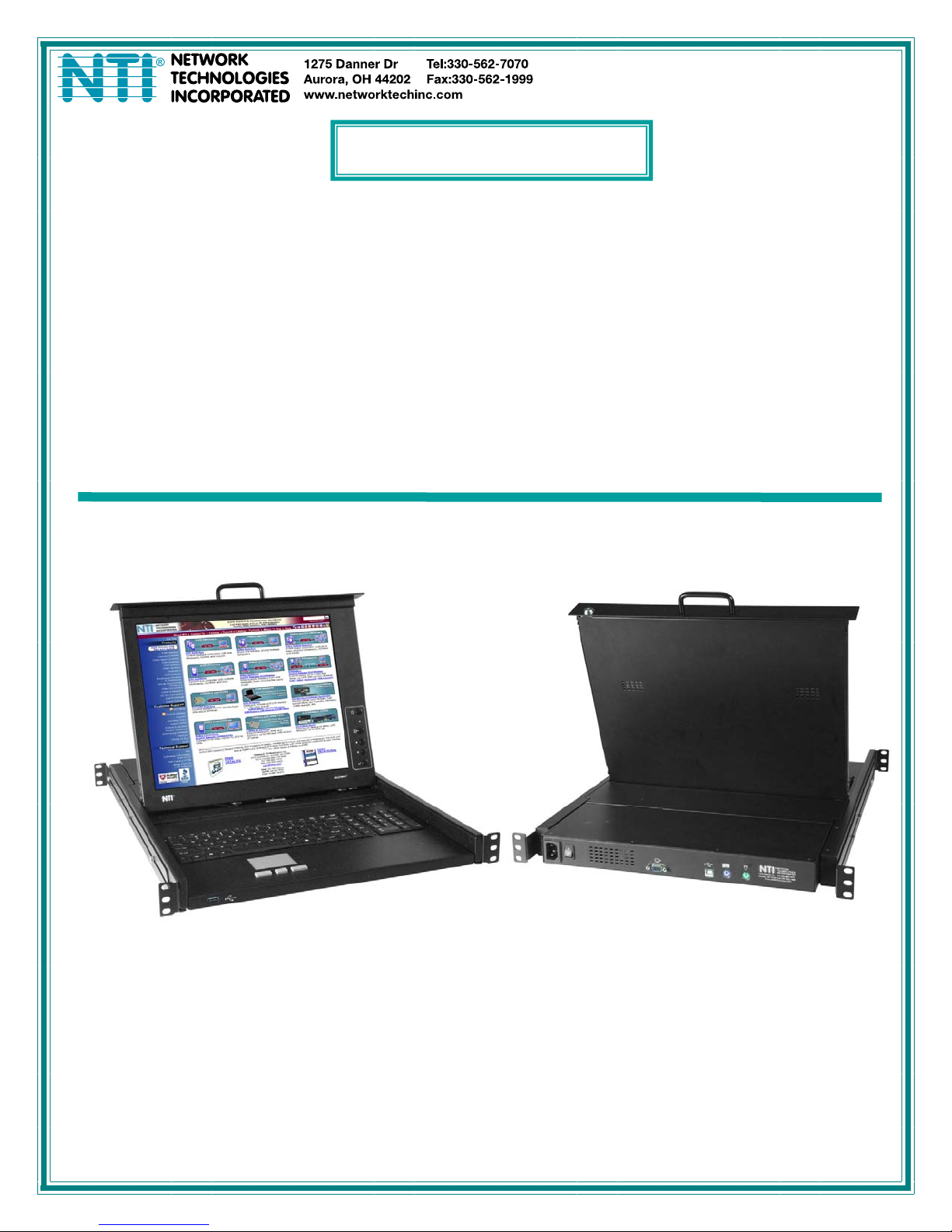
RACKMUX-V17-N (Front and Rear View)
Page 2
TRADEMARK
RACKMUX is a registered trademark of Network Technologies Inc in the U.S. and other countries.
COPYRIGHT
Copyright © 2007, 2015 by Network Technologies Inc. All rights reserved. No part of this publication may be reproduced, stored
in a retrieval system, or transmitted, in any form or by any means, electronic, mechanical, photocopying, recording, or otherwise,
without the prior written consent of Network Technologies Inc, 1275 Danner Drive, Aurora, Ohio 44202.
CHANGES
The material in this guide is for information only and is subject to change without notice. Network Technologies Inc reserves the
right to make changes in the product design without reservation and without notification to its users.
Typographic Conventions
The following table describes the typographic changes used in this instruc t ion.
Typeface
AAaaBBaaCCcc123 On-screen computer output
AAaaBBaaCCcc123
Meaning Example
C:>
What you type, contrasted with on-screen
computer output; keyboard keys to press
C:> L
Press the Fn key
i
Page 3

TABLE OF CONTENTS
Introduction......................................................................................................................................................................1
Features and Functions...................................................................................................................................................2
Installation .......................................................................................................................................................................3
Rack Mounting Instructions .........................................................................................................................................3
Extension Bracket Method........................................................................................................................................3
One-Man Installation Method....................................................................................................................................4
Optional Telco 2-Post Mounting ...............................................................................................................................7
Connect to a CPU........................................................................................................................................................8
Connect Extra Device..................................................................................................................................................9
Remote PC Connection.............................................................................................................................................10
Manual IP Address Change....................................................................................................................................12
Software IP Address Change .................................................................................................................................13
Connect Power..........................................................................................................................................................14
DC Power Option....................................................................................................................................................14
Power Up...................................................................................................................................................................14
Display Functions..........................................................................................................................................................15
Standard Controls......................................................................................................................................................15
OSD Control Menu- 15 and 17 Inch VGA models (-V15/-V17).................................................................................15
OSD Main Menu .....................................................................................................................................................15
Brightness/Contrast Menu......................................................................................................................................16
Color Menu .............................................................................................................................................................16
Position Menu.........................................................................................................................................................16
Setup Menu.............................................................................................................................................................17
OSD Control Menu-DVI Model (-D17).......................................................................................................................17
OSD Main Menu .....................................................................................................................................................17
Brightness/Contrast Menu......................................................................................................................................18
Setup Menu.............................................................................................................................................................18
OSD Control Menu- 17 Inch Hi-Resolution Model (-HR)...........................................................................................19
OSD Main Menu .....................................................................................................................................................19
Keyboard Functions ......................................................................................................................................................21
Function Key Operation..........................................................................................................................................21
Number Pad............................................................................................................................................................22
Other Uses of the Function Key..............................................................................................................................23
Numeric Keypad Option.............................................................................................................................................24
PS/2-USB Keyboard/Mouse Mode............................................................................................................................25
Korean keyboard option................................................................................................................................................26
SAFETY.........................................................................................................................................................................27
Rackmux-KVM Drawer Standard Specifications...........................................................................................................28
General Specs...........................................................................................................................................................28
LCD – 15” ..................................................................................................................................................................28
LCD – 17” ..................................................................................................................................................................28
LCD – 17” Hi-Resolution............................................................................................................................................28
Display Controller: VGA (-15 & -17) ..........................................................................................................................29
Display Controller: DVI (-17)......................................................................................................................................29
OSD Control Board....................................................................................................................................................29
Keyboard....................................................................................................................................................................29
Touchpad...................................................................................................................................................................29
Troubleshooting.............................................................................................................................................................30
Index..............................................................................................................................................................................30
Warranty Information.....................................................................................................................................................30
ii
Page 4

TABLE OF FIGURES
Figure 1- Mount RACKMUX to a standard rack.................................................................................................................................3
Figure 2- Adjustable rail depth...........................................................................................................................................................4
Figure 3- Install cage nuts..................................................................................................................................................................4
Figure 4- Install rail assemblies .........................................................................................................................................................5
Figure 5- Adjust distance between rails.............................................................................................................................................5
Figure 6- Slide the RACKMUX into the rails ......................................................................................................................................6
Figure 7- Secure the RACKMUX.......................................................................................................................................................6
Figure 8- Position RACKMUX with clearance to open.......................................................................................................................7
Figure 9- Mount to Telco post with optional mounting brackets.........................................................................................................7
Figure 10- Connect a PS/2 CPU........................................................................................................................................................8
Figure 11- Connect a USB CPU........................................................................................................................................................8
Figure 12- Cables used for RACKMUX with DVI video support.........................................................................................................9
Figure 13- Connect a USB 1.1 device to the front (optional)..............................................................................................................9
Figure 14- Connect Remote PC to KVM on IP at "LAN" port...........................................................................................................10
Figure 15- Remote Console Preview...............................................................................................................................................11
Figure 16- Login Screen for KVM on IP...........................................................................................................................................12
Figure 17- Network Configuration screen ........................................................................................................................................12
Figure 18- Connect the power cord .................................................................................................................................................14
Figure 19- DC Power Option Terminal Block...................................................................................................................................14
Figure 20- OSD Controls .................................................................................................................................................................15
Figure 21- US(English) Keyboard Layout ........................................................................................................................................21
Figure 22- Keyboard LED Indications..............................................................................................................................................21
Figure 23- Keys of the Number Pad ................................................................................................................................................23
Figure 24- Additional multi-function keys.........................................................................................................................................23
Figure 25- U.S. (English) keyboard with numeric keypad................................................................................................................24
Figure 26- U.K. (English) keyboard with numeric keypad................................................................................................................24
Figure 27- German keyboard with numeric keypad .........................................................................................................................25
iii
Page 5
NTI RACKMUX-V15/17 RACKMOUNT LCD MONITOR WITH KEYBOARD AND MOUSE
INTRODUCTION
The RACKMUX-V15/17 Drawer (RACKMUX) consists of a Keyboard, Touchpad, and LCD monitor integr ated into a 1RU
rack-mountable drawer with wrist pads. When access to a server rack is needed, the drawer can be pulled out and the displa y
lifted up like a notebook computer, revealing the keyboard and mouse. When the drawer is not in use, the display can be folded
forward and down so the 1RU drawer can be pushed into the cabinet easily and smoothly, helping to organize and streamline
busy server rooms. The NTI RACKMUX product line offers a range of KVM Drawer solutions ideal for rack and server
management applications, which will ensure reliability and serviceabi lity.
The RACKMUX will switch between USB and PS/2 standar ds for versatile connection to a CPU. The forward-folding LCD
monitor is offered in either 15” or 17” (designated in the product name as -15 or -17) a nd the video format can be either VGA or
single-link DVI (designated by –V or –D: example RACKMUX-V15). For user input, the drawer offers a notebook-st yle keyboard,
wrist-pad, and a three-button touchpad. The keyboard and mouse can be connected usin g USB and PS/2 cables. USB and PS/2
interfaces will remain active at all times and the keyboard and mouse can be switched, at any time, to use either one. The
RACKMUX-V15/-V17 also provides a front panel USB 1.1 port for the connection of an external USB device.
The keyboard and mouse interface is compatible with Windows platform CPUs. This multiple interface capability reduces
equipment costs by ensuring that a single console is compatible with various PC/server input devices.
Installing the RACKMUX into any server environment will offer:
• A space saving 1RU design, easily mountable in any 19” cabinet/rack
• A forward-folding 15” or 17” T FT LCD with built-in OSD menu for screen adjustments
• Auto shut-OFF switch: Turns OFF the power to the monitor when the LCD is in a folded-closed position.
• Built-in 83-key (US) or 84-key (Europe) keyboard with wrist pad
• Standard 3-button mouse touchpad
• Support for PS2 and USB con nections for the keyboard and mouse.
• Support for VGA (15” or 17” model) or sing le-link DVI signals (17” model only)
• Front-access USB port for easy accessory USB 1.1 device connection
• An internal cab le arm for proper cable management when sliding the drawer open and closed
• Added security with a drawer lock to prevent unwanted access
• Locking rails to prevent movement of the drawer when fully extended
• Built-in univ ersal (100-240VAC) low power consumption power supply
• Multi-languag e support including: US(English), UK(English), German, French, Italian, Spanish
Materials Included with this kit:
9 NTI RACKMUX-V15/17 Drawer with VGA Video support
~or~
9 NTI RACKMUX-D17 Drawer with DVI Video support
9 2 Keys for Lock
9 One-Man Installation Mounting System with hardware
9 IEC Power Cord- country specific
9 CD with a pdf file of this owner's manual and the drawer installation manual
9 USB2-AB-6 6 foot USB 2.0 Type A male-to-USB Type B male cable
9 VVKINT-6-MM 6 foot PS/2 mouse and keyboard cable (not included with KVM on IP model)
9 VEXT-THN-6-MM 6 foot VGA video cable (models with VGA Video support only)
9 DVI-DS-2M-MM 2 meter DVI video cable (model with DVI Video support only)
9 5 foot RJ45-to-RJ45 CAT5 patch cable (model with KVM on IP only)
9 CAT5-CO-MF Crossover Adapter (model with KVM on IP only)
Alternative Cables (not supplied): (available in 3,6,10 and 15 foot lengths)
VKMEXT-xx-MM for VGA Monitor and PS2 Keyboard and Mouse input
USBVEXT-xx-MM for VGA Monitor and USB Keyboard/Mouse input and USB device support
where:
xx is the length of the cable in feet
MM indicates male-to-male connector
Option:
• Numeric keypad option- for a separate 17-key numeric keypad, add “-N” to the part number (i.e. RACKMUX-V17-N)
• KVM on IP option- for a RACKMUX with a KVM on IP unit for remote access, add “-IP” to the part number
(i.e. RACKMUX-V17-N-IP)
• Hi-Resolution Monitor- for a 17” RACKMUX with hi-resolution mon itor (1920 x 1200)- add “HR” to the part number (i.e.
RACKMUX-V17HR (available on 17” models only))
• 24V option- for a RACKMUX that operates at 18-36VDC (24VDC nominal), - add “-24V” to the part number (i.e. RACKMUX-
V17-N-24V)
Cables can be purchased from Network Technologies Inc by calling
(800) 742-8324 (800-RGB-TECH) in the US and Canada or (330) 5627070 (worldwide).
1
Page 6
NTI RACKMUX-V15/17 RACKMOUNT LCD MONITOR WITH KEYBOARD AND MOUSE
18
Front View
RACKMUX-V17
15
21A 21B
13
16
14
17
- or -
(RACKMUX-D17)(RACKMUX-V17)
19
1
2
3
4
5
6
1
7
A
22
9
24
2320
Rear View
RACKMUX-V17
8
Fn
10
PS/2
11 12
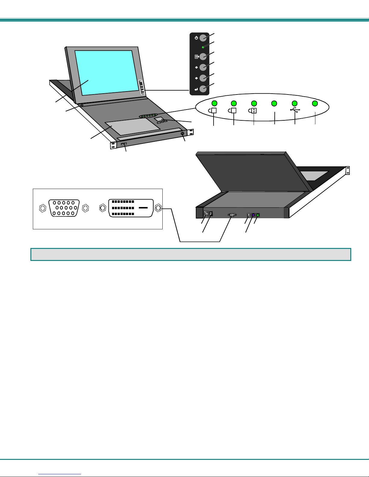
FEATURES AND FUNCTIONS
1. Power Button- press to turn the LCD monitor ON and OFF
2. Power LED- Indicates operation status
Green = Power-ON, Video Input Signal OK
Red = Suspend / Stand-by, or no Video Input Signal
3. Menu Button- press to turn ON the OSD menu
4. Up Arrow Button- press to move the cursor in the OSD menu up
5. Down Arrow Button- press to move the cursor in the OSD menu down
6. Select Button- press to select a menu item (when OSD menu is ON) or press to auto adjust the video quality (when OSD
menu is OFF)
7. NumLock LED- illuminates when the number lock is ON
8. CapsLock LED- illuminates when CapsLock is ON.
9. Scroll Lock LED- illuminates when the Scroll Lock keyboard feature is ON.
10. Fn LED- illuminates when Function Featur es (page 21) are enabled.
11. USB LED- illuminates when RACKMUX drawer is in USB mode
12. PS/2 LED- illuminates when RACKMUX drawer is in PS/2 mode
13. 3-button mouse- for controlling mouse movements on the monitor and controlling the computer
14. Keylock- to prevent unauthorized use of the RACKMUX
15. Auto Shut-OFF- switch automatically shuts OF F the LCD display when the monitor is folded down
16. keyboard- for manual data e ntry and computer control
17. USB Port- USB Type A female- for connection of any USB 1.1 compatible device (such as a flashdrive, printer, etc)
18. LCD Display- for vie wing the video signal from the connected CPU
19. IEC Connector- for attachment of the IEC power cord to power the RACKMUX drawer
20. Switch- for powering ON and OFF the RACKMUX dra wer
21. Video In- 21A. 15HD Female- for connection of the VGA video cable from the CPU (onl y in models that support VGA video)
21B. DVI-D Female- for connection of a DVI-D video cable from the CPU (only in models that support DVI)
22. USB- USB T
23. Keyboard Connector- purple 6 pin miniDIN female- for connection of the PS/2 keybo ard cab le from a PS/2 CPU
24. Mouse Connector- green 6 pin miniDIN female- for connection of the PS/2 mouse cable from a PS/2 CPU
ype B female- for connection of the USB cable from a USB CPU
2
Page 7
NTI RACKMUX-V15/17 RACKMOUNT LCD MONITOR WITH KEYBOARD AND MOUSE
s
INSTALLATION
Rack Mounting Instructions
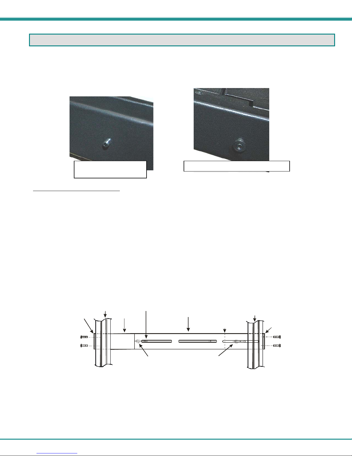
The RACKMUX was designed to be mounted to a rack and includes mounting flanges to make attachment easy. The rails that
are provided for rack mounting will either be empty studs for insertion through slots in a rear extension bracket, or rail guides for
one-man installation to a front and rear bracket set. Depending upon the method provided, install your RACKMUX ac cording to
the instructions below.
Stud for mount to
extension bracket
Guide for one-man installation method
Extension Bracket Method
1. Determine the mounting height in the rack for the drawer. It should be a height comfortable to use the keyboard and see the
LCD display. Mark holes in each of the 4 corner cabinet rails at points all level with each other.
2. Secure the rear brackets to the rear rack cabinet rails. Apply the top screws (supplied) for each bracket to the holes marked in
step 1.
3. Lift the keyboard into position and line the studs on the left and right sides up with the slotted openings in the rear bracket.
Apply the nuts (supplied) to the studs but do not tighten the nuts yet.
FYI: There are 4 mounting studs provided on each side of the RACKMUX. Depending on the depth of the rack and
distance apart of the cabinet rails, the position of the rear bracket may make all 4 studs available for use. In this case,
apply the 2 nuts to the studs furthest apart from each other on each side.
4. Slide the drawer in until the top holes in the front bracket flanges line up with the holes marked in step 1. Secure the front
brackets on the drawer to the front cabinet rails with two screws per bracket. Be sure to tighten the screws securely. Then
tighten the nuts applied in step 3.
5. Apply one more screw to each of the rear brackets to finish.
Front brac ket
flange on dra we r
Secure bracket
to rail using two
screws and nuts
(supplie d)
Front Cabinet
Rail
Drawer
Stud on dra we r
Rear bracket overlapping
drawer
(Rear edge
of dra w er)
Apply nuts ( supplie d) to s t uds and
secure rear brackets to drawer.
Re ar Ca binet
Rail
Rear bracket
flange
Secure bracket
to rail using two
screws and nut
(supplied)
Figure 1- Mount RACKMUX to a standard rack
3
Page 8
NTI RACKMUX-V15/17 RACKMOUNT LCD MONITOR WITH KEYBOARD AND MOUSE
One-Man Installation Method
If you would like to see a video of this installation, see the link on the page that opens when you insert the CD that accompanied
your RACKMUX, or open “single-person-installation.mp4” on the CD.
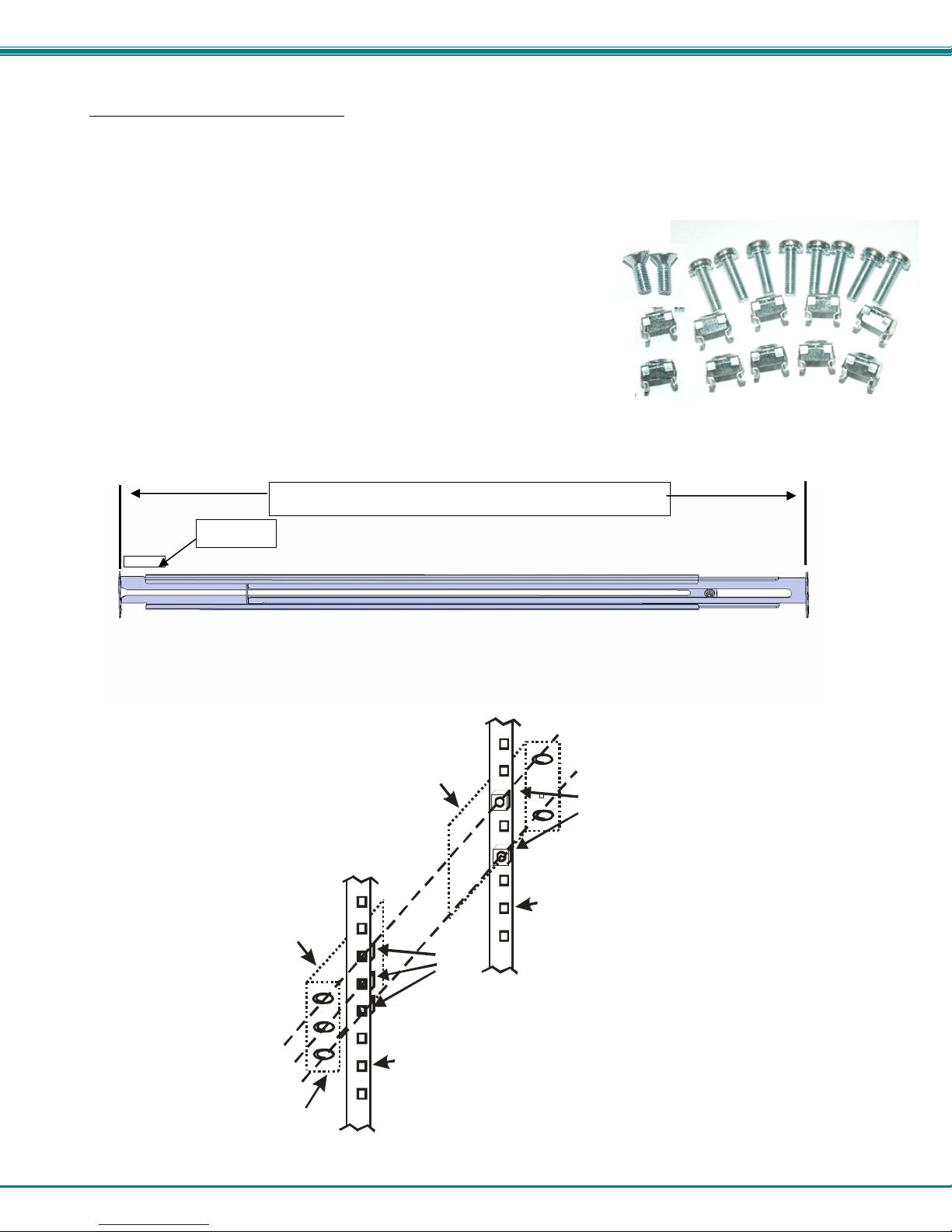
1. Locate and unpack the hardware bag. Your hardware bag will include all items n e cessary to install the specific RACKMUX
model (see the manual that accompanied your RACKMUX drawer), including the following hardware unique to the Single-Person
hardware installation:
• 10- #10-32 cage nut
• 2- #10-32 x 1/2” flat-head machine screw
• 8- #10-32 x 3/4” pan-head machine screw
To install the rails you will need only a tape measure and Phillips screwdriver.
2. Unpack the left and right rail assemblies. Each are labeled “Right Front” and “Left Front” to indicate their intended position and
orientation. Extend each rail assembly to the dimension required for your rack. Rail assemblies are adjustable to fit within a rack
between 24” and 40” in depth.
XXXXX
Labeled
Rail assemblies are adjustable in length from 24” to 40”.
Figure 2- Adjustable rail depth
3. Install six #10-32 cage nuts at the front of the rack in positions where the RACKMUX will be mounted (three in each side).
Install four more cage nuts at the rear of the rack in positions straight across from the upper and lower cage nuts installed in front.
Extender Ra il
Rail Flange
Extender Ra il
Cage
Nuts
Rear Rack
Support
Cage
Nuts
Front R ack
Support
Figure 3- Install cage nuts
4
Page 9

NTI RACKMUX-V15/17 RACKMOUNT LCD MONITOR WITH KEYBOARD AND MOUSE
4. Install the right rail assembly. The end with the label “Right Front” mounts to the front rack support. Install only the center
screw through the rail flange to the rack support and cage nut using the #10-32 x 1/2” flat head machine screw provided. (See
image below.) Do not tighten at this time. Install the left rail assembly in the same fashion. The end with the label “Left Front”
mounts to the front rack support.
5. Install two #10-32 x 3/4” pan-head screws in the rear of each rail assembly as shown below. Do not tighten at the time.
Install one flat
head screw in
the center in
each side at the
front
Rack Rear
Rack Front
Install two
screws in each
side at the rear
Figure 4- Install rail assemblies
6. Measure the distance between the inside of the rails at the front of the rack. Adjust the distance to 17-1/4” and tighten the flathead screws to the rail flanges securely.
Left Rail
Front Rack Supports
Figure 5- Adjust distance between rails
Right Rail
17-1/4"
5
Page 10
NTI RACKMUX-V15/17 RACKMOUNT LCD MONITOR WITH KEYBOARD AND MOUSE
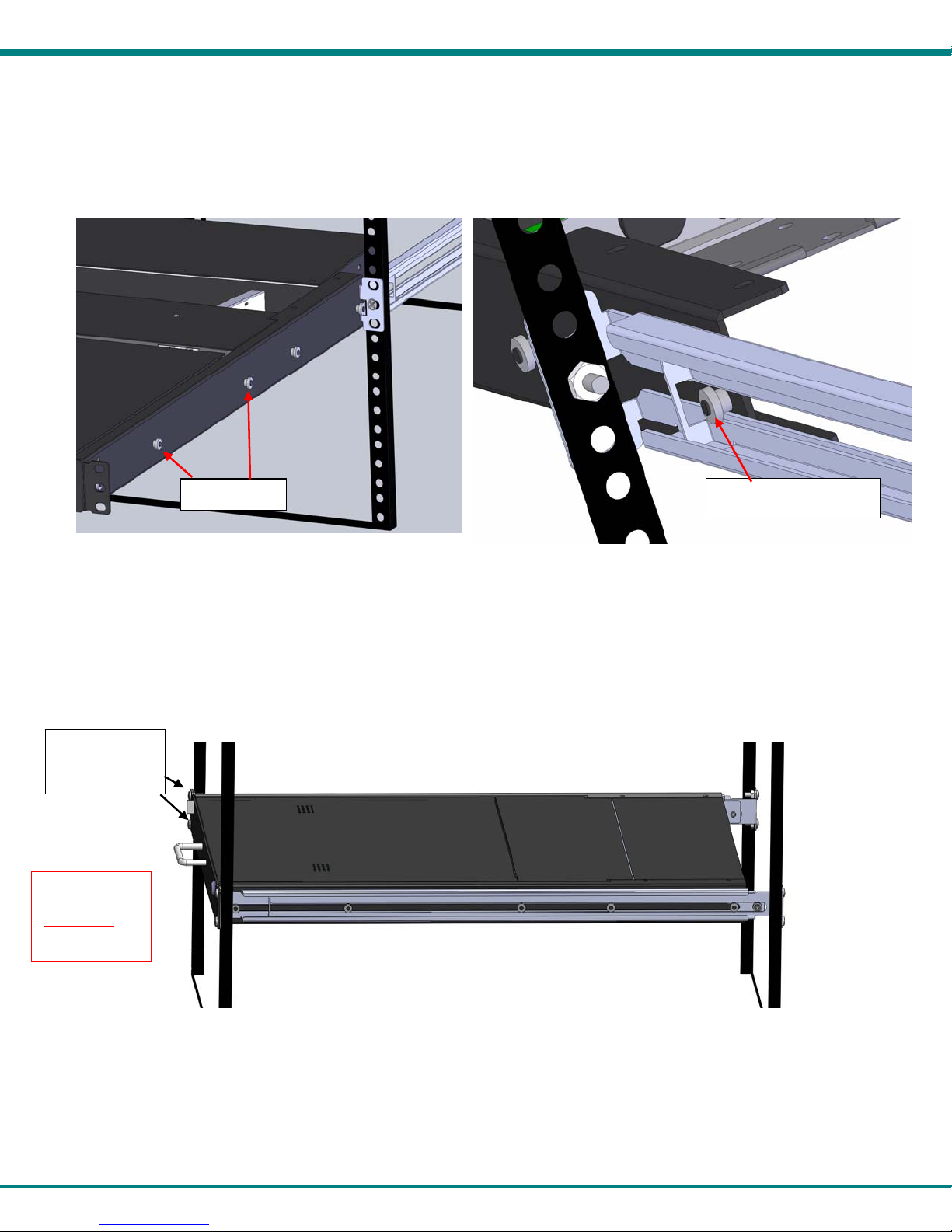
7. Lineup the rail guides on the RACKMUX drawer with the slots in the front of the left and right rails and slide the drawer into the
rack. The rail guides should be positioned such that the wide lip of the guide is on the backside of the rail. Slide the drawer i n
completely.
View of rail guide from the front of the rack support View of rail guide from the backside of the rail
Rail guides
Wide lip of rail guide
Figure 6- Slide the RACKMUX into the rails
8. Apply four more #10-32 x 3/4” pan-head machine screws (two for each) through the holes in the drawer flanges, through the
holes in the left and right rails, into the cage nuts in the rack supports. Tighten each securely.
Apply two
more screws
on each side
There should
be a total of
six screws
the front now.
at
Figure 7- Secure the RACKMUX
9. Tighten securely the four screws applied to the rear rail flanges in step 4.
6
Page 11
NTI RACKMUX-V15/17 RACKMOUNT LCD MONITOR WITH KEYBOARD AND MOUSE
Note: To provide sufficient room for the LCD monitor to be opened to a p ro per viewing angle (a minimum 90 degree
position from the keyboard), ensure that all devices mounted above the RACKMUX extend no more than 1.75” from the
rack frame. (See Figure 8)
"X" must be
less than 1.75"
for LCD to open
to full 90
90
Side View of RACKMUX
Server mounted
X
above RACKMUX
in the same rack
Figure 8- Position RACKMUX with clearance to open
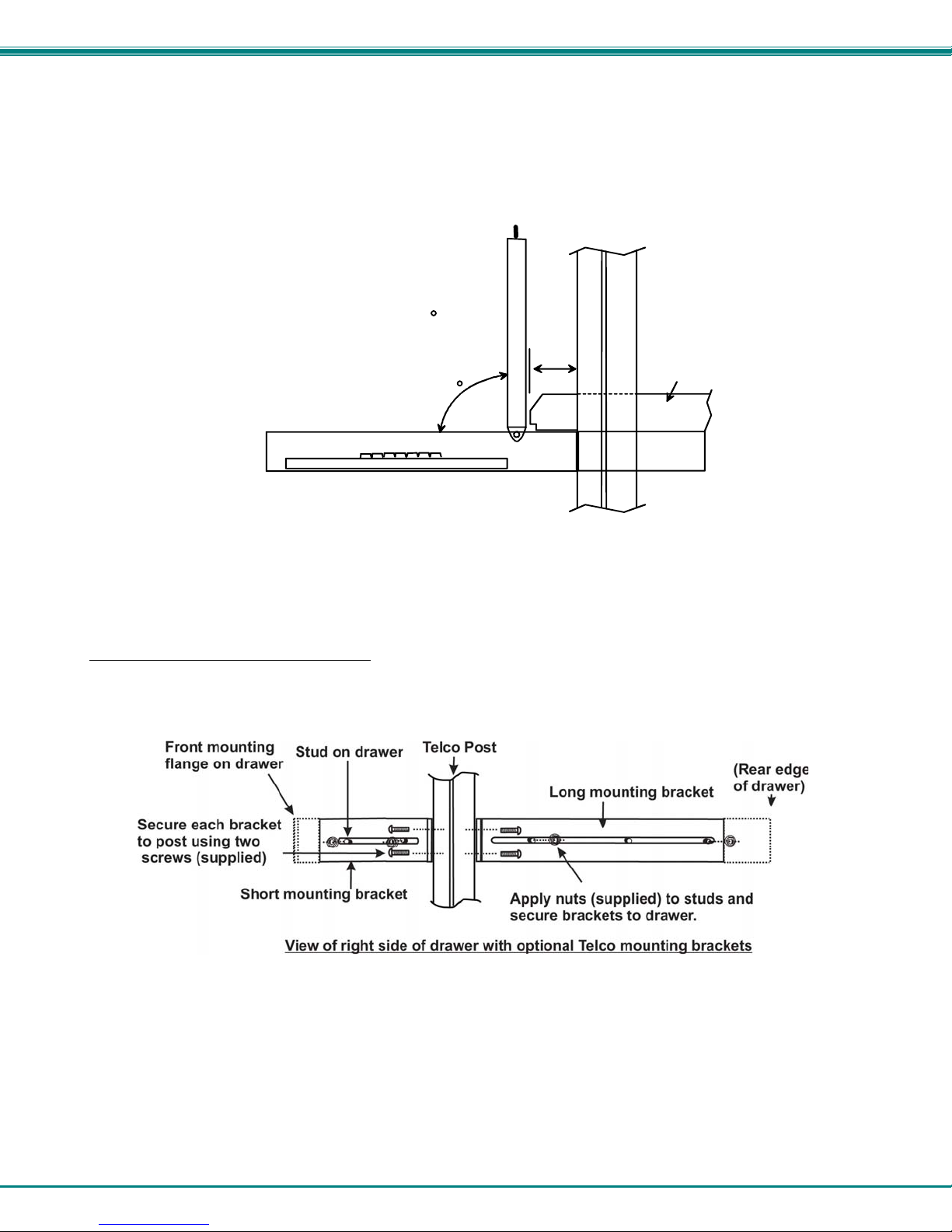
Optional Telco 2-Post Mounting
If the Telco 2-post mounting bracket kit (NTI# RL-T15-TEL) is to be used, secure the short and long br ackets to each side of the
drawer as shown in Figure 9. Apply 2 nuts (supplied) per bracket to secure the brackets to the drawer. Apply two #10-32x3/4”
screws (supplied) per bracket to the post at the desired height. Slots are provided in the brackets to make minor depth
adjustments easy. Be sure to properly tighten all nuts and screws before using the drawer.
Figure 9- Mount to Telco post with optional mounting brackets
7
Page 12

NTI RACKMUX-V15/17 RACKMOUNT LCD MONITOR WITH KEYBOARD AND MOUSE
Connect to a CPU
The RACKMUX may be connected to either a PS/2 or a USB CPU with a VGA video port. To connect to a PS/2 CPU, use a
VEXT-6-MM cable and VVKINT-6-MM cable as shown in Figure 10. To connect to a USB CPU, use the VEXT-6-MM and
USB-AB-6 cables as shown in Figure 11.
Figure 10- Connect a PS/2 CPU
Figure 11- Connect a USB CPU
8
Page 13

NTI RACKMUX-V15/17 RACKMOUNT LCD MONITOR WITH KEYBOARD AND MOUSE
When connecting a CPU with DVI support to the single-link DVI port of the RACKMUX, use a DVI-DS-2M-MM (supplied) for the
DVI video signal, a USB2-AB-6 (supplied) for the USB connection, and if using PS/2 keyboard and mouse connections, connect
a VVKINT-6-MM cable (supplied) between the CPU and RACKMUX.
Figure 12- Cables used for RACKMUX with DVI video support
Connect Extra Device
On the front of the RACKMUX is an additional USB Type A port to be used, if desired, for an extra accessory. Any low or full
speed USB device may be connected to this port to be used. This port is fully compliant with USB standard 1.1.
Note: In order for the optional USB device port to be usable, the USB port on the rear of the RACKMUX must be
connected to a USB enabled CPU (a 6 foot USB cable is supplied).
Note: If a USB keyboard or mouse is connected, operation of the RACKMUX keyboard or mouse may cause
unpredictable results. Do not try to use both mice or both keyboards at the same time.
Connect optional USB 1.1 or 2.0 device
PRINTER
CAMERA
FRONT VIEW OF RACKMUX-V17
SCANNER
FLASH DRIVE
Figure 13- Connect a USB 1.1 device to the front (optional)
Note: If a USB 2.0 device is connected to the optional USB device port, it will operate at USB 1.1 speed.
9
Page 14

NTI RACKMUX-V15/17 RACKMOUNT LCD MONITOR WITH KEYBOARD AND MOUSE
Remote PC Connection
The RACKMUX with KVM on IP unit includes a port for Ethernet connection to your LAN. If you have purchased the RACKMUX
with KVM on IP (i.e. RACKMUX-V17-N-IP), follow these instructions to make your connections for remote access.
1. Make a connection between an available RJ45 Ethernet port on a PC and the ”LAN” port on the RACKMUX. A five foot patch
cable and crossover adapter have been included for this purpose.
Figure 14- Connect Remote PC to KVM on IP at "LAN" port
2. The default IP address of the KVM on IP is 192.168.0.70.
If 192.168.70 is not compatible with your subnet, you may want to change the IP address of the KVM on IP to one that is. To
change the IP address of the KVM on IP, either follow the “Manual IP Address Change” or the “Software IP Address Change”
methods described on page 12 and page 13 .
3. Enter the IP address in the browser URL address block. .
4. Log into the KVM on IP. Enter the default user name and password for the KVM on IP:
Username = super
Password = pass
10
Page 15

NTI RACKMUX-V15/17 RACKMOUNT LCD MONITOR WITH KEYBOARD AND MOUSE
5. With a proper login, a window “Remote Console Preview” will be displayed. Click on the link “Click to open”.
Figure 15- Remote Console Preview
A connection will be made between your remote PC and the RACKMUX Drawer. The screen that opens is a virtual PC that
enables you to control the RACKMUX just as if you were actually at the keyboard of the RACKMUX. Using the mouse, switch
between the virtual PC and your actual computer interface.
If the remote connection is closed while in the KVM on IP menu, to re-open the connection click on “Remote Control”, then
“KVM Console”.
Note: There are more features available in the menu for the KVM on IP, but their use or configuratio n is not necessary in
the operation of the RACKMUX-V17-N-IP.
11
Page 16

NTI RACKMUX-V15/17 RACKMOUNT LCD MONITOR WITH KEYBOARD AND MOUSE
Manual IP Address Change
1. The Ethernet port on the PC must be configured with an IP of 192.168.0.xxx where xxx is any number except 70.
(You may need to configure the Ethernet port network information on the PC such that it can connect to the KVM on IP device
in the RACKMUX.)
Note: Connecting to the KVM on IP requires the installation of the Java Runtime Environment. A link to the web page
from which it can be downloaded and installed is provided on the Product Manual CD in addition to a Windows
compatible copy of the application itself.
2. Open a browser window on the PC. Type “192.168.0.70” into the URL address block. A login prompt will appear.
Figure 16- Login Screen for KVM on IP
3. Enter the default user name and password for the KVM on IP:
Username = super
Password = pass
4. The KVM on IP will open the main menu. To change the network configuration, go to “Device Settings”, and then “Network” to
open the network configuration settings page for the KVM on IP.
Figure 17- Network Configuration screen
12
Page 17

NTI RACKMUX-V15/17 RACKMOUNT LCD MONITOR WITH KEYBOARD AND MOUSE
5. Enter the desired network connection settings (IP address, subnet mask, gateway) as compatible with your network.
Make note of these settings in case you need them later.
6. With the settings updated, press “Apply” to implement the changes in the KVM on IP. Your browser connection to the KVM
on IP is no longer valid.
7. To restore connection to the KVM on IP, change the IP address on the PC back to an address compatible with your network
and now also compatible with the KVM on IP.
Having configured the KVM on IP to be compatible with your network, you can now make a direct cable connection (crossover
adapter not needed) to your network through a router or switch.
Software IP Address Change
1. Locate the program psetup.exe on the CD this manual is found on, in the “KVMonIP” subdirectory. Double-click on it.
2. Click Refresh Devices. The program will detect any network connected IP-KVM devices and display them by their MAC
addresses.
3. Click Query Device to find the current IP configuration of the selected MAC address device.
4. Set IP auto configuration as “None”; and enter the new IP address and Subnet mask.
5. Enter
6. Click Setup Device. If the “super” login was authenticated, it’ll show “Successfully configured device”. Otherwise it will show
“Permission Denied”.
7. With a successful IP address change, login to the KVM on IP using your browser.
super and pass as the login and password.
13
Page 18

NTI RACKMUX-V15/17 RACKMOUNT LCD MONITOR WITH KEYBOARD AND MOUSE
Connect Power
Connect the IEC power cord to the power port as shown below.
Figure 18- Connect the power cord
DC Power Option
The RACKMUX is available with connections for DC power. Models with “-24V” can be connected to an 18~36VDC (24VDC
nominal) power supply. It has connections on the rear for a user-supplied DC power supply (minimum 30 watt). This is typically
used when the RACKMUX is installed in a Telecom environment.
The RACKMUX with this feature will accept a DC power source with positive or negative polarity. A removable 3-pole screw
terminal is provided for easy connection.
Figure 19- DC Power Option Terminal Block
Power Up
Power up the RACKMUX and connected computer in this order.
1. Power On the RACKMUX
2. Power ON the attached CPU.
If a device is plugged into the USB port on the front of the RACKMUX, it can powered-ON at any time.
Note: During power-up, do not attempt to type or otherwise use the keyboard. Doing so may result in boot errors and
loss of keyboard and mouse.
14
Page 19

NTI RACKMUX-V15/17 RACKMOUNT LCD MONITOR WITH KEYBOARD AND MOUSE
DISPLAY FUNCTIONS
An NTI RACKMUX with a 17” monitor supports resolutions up to SXGA (1280 x 1024) and a 15” monitor supports resolutions up
to XGA (1024 x 768), each with a refresh rate at between 55 and 76Hz. The quality of the image on the LCD monitor is adjustable
using an On Screen Display (OSD) menu using the control buttons on the RACKMUX.
Standard Controls
The RACKMUX has 5 standard control buttons and a power LED. The 5 standard control buttons o perate as follows:
• The Power button turns the R ACKMUX LCD and backlight ON and OFF as desired.
• The Power LED located immediately below the Power button is a dual color
LED. It will illuminate with a green color when the RACKMUX is powered
ON and working properly. It will illuminate with a red color if the RACKMUX
is powered ON but there is no input signal detected.
• The Menu button is used to bring up the OSD menu where the various
settings of the LCD display can be adjusted. Once the OSD screen is
displayed, the Menu button is used to make selections within the menus.
See "OSD Control Menu" (below) for more on LCD display settings.
• The Up and Down Arrow buttons are used to navigate through the menus.
Move the cursor up or down as desired to highlight an item for selection.
Once an item is highlighted, pressing the Menu button will select it.
Power
ON/OFF
Power LED
Menu
Up Arrow
Down Arrow
Select/
Auto Adjust
Controls for the
OSD Menus
Figure 20- OSD Controls
• The Select button is used to make selections within the OSD menus when the OSD menu is ON. When the OSD menu is
OFF, the Select button will act as an Auto Adjust button to keep the user from having to use the menus to adjust the quality
of the image on the monitor.
OSD Control Menu- 15 and 17 Inch VGA models (-V15/-V17)
The OSD (On Screen Display) Menu enables the user to select the desired characteristics of the LCD display. To activate the
OSD Menu, press the Menu button (above). To turn the Menu back OFF, either select "EXIT" from the main menu or just wait
10-60 seconds and it will automatically be cleared from the screen.
OSD Main Menu
Selection Purpose Range
Brightness/Contrast Increase/decrease panel brightness/contrast level 1-100
Color R,G,B color temperature control 1-100
Position
Setup
Exit Exit from the OSD control menu
• Video Image horizo ntal and vertical position control
• Clock setting
• Phase control
• Control OSD Image positio n on screen
• Set time OSD will stay on screen before auto shutoff
• Select the language of the OSD menu
1-100
-10 to 60 seconds
Several languages (see page 8)
15
Page 20

NTI RACKMUX-V15/17 RACKMOUNT LCD MONITOR WITH KEYBOARD AND MOUSE
Brightness/Contrast Menu
Selecting the Brightness/Contrast menu will bring up a screen in which the user can adjust the brightness and contrast levels of
the LCD display. Using the Up or Down Arrows to navigate the menu, highlight either the BRIGHTNESS or CONTRAST
sections and press the Select button to choose the option to adjust. Then use the Up or Down Arrow to adjust the setting.
Select EXIT when finished to return to the Main Menu.
Color Menu
Selecting the Color menu will bring up a screen in which the user can adjust the Red, Green, and Blue color levels (values from 1-
100) of the LCD display. With the RED, GREEN, or BLUE sections highlighted, (use the Up or Down Arrow to move between
them), press the Select button to choose the option to adjust. Then use the Up or Down Arrow to adjust the setting.
Select EXIT when finished to return to the Main Menu.
Position Menu
Selecting the Position menu will bring up a screen in which the user can select AUTO ADJUST to automatically adjust the
horizontal and vertical position of the displayed image on the monitor, as well as adjust the clock and phase settings if they are not
correct. The user can also individually adjust these settings if so desired. With any of the sections highlighted, (use the Up or
Down Arrow to move between them), press the Select button to choose the option to adjust. Then use the Up or Down
Arrow to adjust the setting as needed. Select EXIT when finished to return to the Main Menu.
16
Page 21

NTI RACKMUX-V15/17 RACKMOUNT LCD MONITOR WITH KEYBOARD AND MOUSE
Setup Menu
Selecting the Setup menu will bring up a screen in which the user can adjust
OSD POSITION-the position of the OSD menus on the LCD display
OSD TIME-the length of time the user can be idle before the OSD menu automatically exits (adjustable from 10
to 60 seconds)
LANGUAGE-the language th at the OSD menus will be presented in
With the item highlighted, (use the Up or Down arrow to move between them), press the Select button to choose the option to
adjust. Then use the Up or Down Arrow to adjust the setting as needed. Select EXIT when finished to return to the Main
Menu.
OSD Image can be moved
to different points on the
display
OSD Control Menu-DVI Model (-D17)
The OSD (On Screen Display) Menu enables the user to select the desired characteristics of the LCD display. To activate the
OSD Menu, press the Menu button (page 15). To turn the Menu back OFF, either select "EXIT" from the main menu or just
wait 10-60 seconds and it will automatically be cleared from the screen. Any changes made before exiting the menu will be
saved.
OSD Main Menu
Note: In order to display the OSD Menu, the RACKMUX must first be connected to a video source (see “Connect to a
CPU” – page 8).
Note: If menu does not appear when the Menu button is pressed, the monitor may be set fo r a “PC” (VGA) input source.
Press the Up Arrow button on the monitor to switch it to a “Digital” (DVI) input source.
17
Page 22

NTI RACKMUX-V15/17 RACKMOUNT LCD MONITOR WITH KEYBOARD AND MOUSE
Selection Purpose Range
Brightness/Contrast Increase/decrease panel brightness/contrast level 1-100
Setup
Exit Exit from the OSD control menu
• Control OSD Image positio n on screen
• Set time OSD will stay on screen before auto shutoff
• Select the language of the OSD menu
• Select Input Source to display
• 0-4
• 10 to 60 sec on ds
• English, Spa nish, German, Italian, or French
• Digital or PC (must
be set to Digital)
Brightness/Contrast Menu
Selecting the Brightness/Contrast menu will bring up a screen in which the user can adjust the brightness and contrast levels of
the LCD display. Using the Up or Down arrows to navigate the menu, highlight either the BRIGHTNESS or CONTRAST sections
and press the Select button to choose the option to adjust. Then use the Up or Down Arrow to adjust the setting.
Select EXIT when finished to return to the Main Menu.
Setup Menu
Selecting the Setup menu will bring up a screen in which the user can adjust
OSD POSITION-the position of the OSD menus on the LCD display (positions 0-4)
OSD TIME-the length of time the user can be idle before the OSD menu automatically exits (adjustable from 10
to 60 seconds)
LANGUAGE-the language th at the OSD menus will be presented in
INPUT SOURCE- the type of signal that is coming from the CPU, either Digital (DVI) or PC (VGA)
NOTE: As used on this RACKMUX, the INPUT SOURCE must be set
With the item highlighted, (use the Up or Down Arrow to move between them), press the Select button to choose the option to
adjust. Then use the Up or Down Arrow to adjust the setting as needed. Select EXIT when finished to return to the Main
Menu.
OSD Image can be moved
to different points on the
display
to “Digital”.
18
Page 23

NTI RACKMUX-V15/17 RACKMOUNT LCD MONITOR WITH KEYBOARD AND MOUSE
OSD Control Menu- 17 Inch Hi-Resolution Model (-HR)
The OSD (On Screen Display) Menu enables the user to select the desired characteristics of the LCD display. To activate the
OSD Menu, press the Menu button (below). To turn the Menu back OFF, either press the Exit button or just wait
approximately 10 seconds (timing is adjustable) and it will automatically be cleared from the screen. Any changes made before
exiting the menu will be saved.
OSD Main Menu
The Main Menu is broken into five sections, Color, Picture, Function, OSD Menu, and Misc. Press one of the arrow buttons to
move between them. The Picture and Function sections only apply when the RACKMUX is connected as VGA instead of DVI.
To select a menu and move to characteristics within them (i.e. CSM, Brightness, or Contrast under the Picture menu), press the
Select button while the desired menu is displayed.
Characteristics that can be adjusted are described in the chart below.
Selection Purpose Range
Colour
Contrast
Brightness
Colour Temp.
Colour Adjust
Picture (VGA Only)
H Position
V Position
Phase
Clock
Sharpness
Function (Fx)
(VGA Only)
• Increase/decrease panel contrast level
• Increase/decrease panel brightness level
• Set panel color temperature
• Select RGB balanc e (goes to submenu)
• Control Horiz ontal position of screen
• Control Vertical positi on of screen
To manually force auto adjust of monitor settings Select Auto Adjust or Auto Color functions
• 0-100
• 0-100
• 5800K,9300K,6500K,User
• 0-100
• 0-100
• 0-100
• 0-100
• 0-100
• 1-5
19
Page 24

NTI RACKMUX-V15/17 RACKMOUNT LCD MONITOR WITH KEYBOARD AND MOUSE
OSD Menu
Language
OSD H. Pos.
OSD V. Pos.
OSD Timer
Translucent
• Select the language of the OSD menu
• Control Horiz ontal OSD Image position on screen
• Control Vertical OSD Image p osition on screen
• Control if OSD will time out
• Adjusts how boldly the menu is displayed
Misc.
• Select Input
• Reset monitor to default settings
Press the Exit button or select “Exit” to exit the OSD menu.
• English, Spa nish, German, Italian, or French
• 0-100
• 0-100
• On/Off If On, select 3-100 seconds.
• -/+
• VGA or DVI
• Yes/No
Colour Adjust submenu
Input submenu
20
Page 25

NTI RACKMUX-V15/17 RACKMOUNT LCD MONITOR WITH KEYBOARD AND MOUSE
KEYBOARD FUNCTIONS
The keyboard on the RACKMUX-Vxx is a standard condensed Windows format. To reduce the keyboard size, some keys have
been assigned multiple functions, accessible via the "Fn" key. This section will describe which keys have multiple functions and
how to enable them. Use the LEDs to know what special features are enabled.
Function Key Operation
The Function (“Fn”) key provides several special functions on the RACKMUX keyboard, including:
enabling otherwise standard keyboard keys to be used as the keys of a numeric keypad
enabling multi-function keys to change operation
enabli ng the “T” key to act as a mode key to toggle between USB and PS/2 keyboard/mouse mode
To turn ON (lock) the Function key, press the “Fn” key twice quickly (double-click). The “Fn” LED will illuminate.
To turn OFF (unlock) the Function key, press the “Fn” key twice quickly again. The “Fn” LED will turn OFF.
Note: The "Fn" key will also operate similar to the shift key (with only momentary effect). Press and hold the "Fn" key
prior to pressing the special function key. The "Fn" key will remain active as long as it is depressed.
Esc
~
`
F2
F1
!
1
F3
F4
@
#
2
$
3
4
F6
F5
%
5
F7
F8
F9
&
^
7
6
*
8
789
F10
(
9
F11 F12
)
0
Tab
WE R
Q
CapsLock
ASDF GHJK L
Shift
ZXCVB
T
YU I OP
123
M
N
654
<
,
Ctrl
Fn
Alt
Alt
Function Key to enable additi onal key functions
Num Lk
Insert Delete
Prt Sc
+
=
}
{
]
[
Enter
:
"
;
'
+
*
>
.
?
Shift
/
.
/0
Ctrl
Home
Sys Rq
Backspace
Enter
Pg Up
Pause
BreakScr Lk
\
EndPg Dn
1
On= NumLock
is locked
Figure 22- Keyboard LED Indications
Figure 21- US(English) Keyboard Layout
On= Function
On= CapsLock
is locked
A
On= Scroll Lock
is locked
Key feature
is ON
Fn
On= USB
Keyboard/Mouse
mode
21
On= PS/2
Keyboard/Mouse
mode
PS/2
Page 26

NTI RACKMUX-V15/17 RACKMOUNT LCD MONITOR WITH KEYBOARD AND MOUSE
Number Pad
The functionality of a Number Pad on a standard Windows keyboard has been incorporated into the keyboard of the
RACKMUX-V15 (see Figure 23, page 23 ).
To substitute the keys of the Number Pad:
1. Press the "NumLock" key. The NumLock LED ( ) will illuminate.
2. Press the "Fn" key twice quickly (double-click). The "Fn" LED will illuminate.
To turn OFF Number Pad functions:
1. Press the "Fn" key twice quickly (double-click). The "Fn" LED will turn OFF.
2. Press the "NumLock" key. The NumLock LED ( ) will turn OFF.
With the Fn and NumLock LEDs illuminated, pressing some standard keys will result in displaying characters as
indicated in the chart below.
Standard Key Displayed when NumLock is
j
k
l
u
j
o
7
8
9
m
.
(period)
/
(forward slash)
;
(semicolon)
’
(apostrophe)
-
(hyphen)
[
(left bracket)
ON
1
2
3
4
5
6
7
8
9
0
.
(period)
1
1
Function when NumLock is
OFF
End
Down Arrow
Page Down
Left Arrow
---
Right Arrow
Home
Up Arrow
Page Up
Insert
Delete
/
(forward slash)
+
(plus sign)
*
(asterisk)
-
(minus sign)
ENTER
22
Page 27

NTI RACKMUX-V15/17 RACKMOUNT LCD MONITOR WITH KEYBOARD AND MOUSE
&
7
789
*
8
(
9
Num Lk
Scr Lk
UIO
654
{
[
Enter
JKL
123
:
;
+
"
'
*
M
>
.
.
?
/
/0
Figure 23- Keys of the Number Pad
Other Uses of the Function Key
The Function ("Fn") key (page21) will enable other standard keyboard features in addition to the Number Pad keys (page 22) .
Key Function when Fn key is
not locked ("Fn" LED is OFF)
Numlck (Number lock) Scr Lck (Scroll Lock)
Insert Prt Sc (Print Screen)
Delete Sys Rq (System Requirements)
Pause Break
Up Arrow Page Up
Down Arrow Page Down
Left Arrow Home
Right Arrow End
Num Lk
Scr Lk
Insert Delete
Prt Sc
Sys Rq
Pause
Break
Key Function when Fn key is
Locked ("Fn" LED is ON)
Pg Up
Home
EndPg Dn
Note: The "Fn" key will also operate similar to the shift key (with only momentary effect).
Figure 24- Additional multi-function keys
23
Page 28

NTI RACKMUX-V15/17 RACKMOUNT LCD MONITOR WITH KEYBOARD AND MOUSE
Numeric Keypad Option
Models with the Numeric Keypad option (-N) (i.e. RACKMUX-V15-N) have a standard Windows keyboard with 17-key numeric
keypad.
When the Numeric Keypad option is present, the Function (“Fn”) key, (page 21) is only used to toggle between PS/2 and USB
keyboard/mouse mode (page 25).
Note: When the Numeric Keypad option is present, the "Fn" key does not lock. Instead, the “Fn” key operates similar to
the shift key (with only momentary effect).
Esc
F2
F1
!
~
1
`
Tab
Q
Caps Lock
Shift
Fn
Ctrl
Function Key
F3
F4
@
#
2
$
3
4
WE R
F6
F5
%
5
F7
F8
F9
F10
&
^
7
6
T
YU I OP
(
*
9
8
F11 F12
)
0
ASDFGHJKL
<
ZXCVB
Alt
M
N
,
Alt
:
;
>
.
PrtSc
SysRq
{
[
?
/
Insert
Scroll
Pause
Delete
Break
Lock
+
Backspace
=
}
]
"
Enter
'
Shift
Home
Page
\
Up
Page
Down
End
Num
Lock
/
789
Home P g Up
456
123
End
0
Ins
*
PgDn
.
Del
-
+
Enter
Figure 25- U.S. (English) keyboard with numeric keypad
Esc
`
Tab
Caps Lock
Fn
Shift
F2
F1
!
1
Q
F3
F4
"
2
$
3
4
WE R
F6
F5
%
5
F7
F8
F9
&
^
7
6
T
YU I OP
*
8
ASDFGH JK L
ZXCVB
Ctrl
Alt
\
M
N
AltGr
F10
(
9
F11 F12
)
0
<
,
PrtSc
SysRq
{
[
:
@
;
'
?
>
.
/
Insert
Figure 26- U.K. (English) keyboard with numeric keypad
Pause
Scroll
Lock
+
Backspace
=
}
]
Break
Delete
Home
~
Page
Up
#
Num
Lock
/
*
789
Home
PgUp
-
+
Enter
Shift
Page
Down
End
456
123
End
0
Ins
PgDn
.
Del
Enter
24
Page 29

NTI RACKMUX-V15/17 RACKMOUNT LCD MONITOR WITH KEYBOARD AND MOUSE
Esc
^
F2
F1
"
!
2
1
Tab
@
Q
ASDFGH JK L
F3
2
3
3
F4
$
4
F5 F6 F7
WE R
F8
F9 F10
(
%
5
T
/
&
7 {
6
8 [
ZU I OP
)
9 ]
F11 F12
=
0 }
Druck
S-Abf
?
\
U
O
A
Rollen
*
+ ~
Pause
Untbr
Entf
Pos1
Bild
'
#
Bild
Num
789
Pos1
456
/
YXCVB
N
Strg
Fn
>
Alt
<
;
M
u
AltGr
.
Einfg
:
,
Ende
123
Ende
0
Figure 27- German keyboard with numeric keypad
PS/2-USB Keyboard/Mouse Mode
The RACKMUX keyboard and mouse can be configured to connect to either a PS/2 or USB enabled CPU. At initial power ON
from the factory, the keyboard will be in PS/2 mode.
To toggle keyboard mouse mode when standard condensed keyboard is present
1. Press the "Fn" key twice quickly (double-click). The "Fn" LED will illuminate.
2. To toggle the keyboard to USB mode, depress and hold the “T” key for at least 7 seconds. The “USB” LED will
illuminate. Release the “T” key.
3. To toggle the keyboard back to PS/2 mode, press and hold the “T” key again for at least 7 seconds. The “PS/2” LED
will illuminate. (See Figure
To toggle keyboard mouse mode when Numeric Keypad is present
1. To toggle the keyboard to USB mode, depress and hold the “Fn“ key (“Fn” LED will illuminate) and the “T” key for at
least 7 seconds. The “USB” LED will illuminate. Release both keys.
2. To toggle the keyboard back to PS/2 mode, press and hold the “Fn” and “T” keys again for at least 7 seconds. The
“PS/2” LED will illuminate. (See Figure 22 on page 13.) Release both keys.
Note: In the event of a power failure, the RACKMUX will power up the keyboard in the mode it was last configured for.
22 on page 13.) Release the “T” key.
Bild
Bild
-
*
+
Enter
.
Entf Einfg
25
Page 30

NTI RACKMUX-V15/17 RACKMOUNT LCD MONITOR WITH KEYBOARD AND MOUSE
KOREAN KEYBOARD OPTION
This RACKMUX may include an optional keyboard with special characters on the keys unique to the Korean language. If so,
the firmware in the drawer provides special functions to be used for switching between typing in English, “Alternate Language 1”
(as configured in your Windows operating system) and “Alternate Langua ge 2”.
For this application, we will assume that Alternate Language 1 is configured for Korean characters (Hangeul) and Alternate
Language 2 is for Chinese characters (Hanja).
Alternate Language 1
To switch between typing characters in English and typing in the language configured as “Alternate Language 1” (Korean), press
the right hand <Alt> key on the keyboard. To switch back to typing characters in English, press the right hand <Alt> key
again.
Alternate Language 2
To use the “Alternate Language 2” character conversion pop-up function as configured in your Windows operating system,
1. press the right
then
2. key in the Korean character to be converted to Chinese
3. press and hold the <Fn> key, then press the left hand <Alt> key and release both. (Pressing these keys substitutes for
the Hanja key on a Korean keyboard)
If the character entered has a Chinese equivalent, a popup will be presented for you to select the desire d character to be
substituted. If there is no Chinese equivalent, no popup will be presented.
To make the pop-up menu re-appear, enter another Korean character sequence and repeat the <Fn> + <Alt> key sequence.
Press and hold <Fn>, then press <Alt>
to access the Alternate Language 2
(Hanja) conversion pop-up menu
Hanja Key
hand <Alt> key to switch to “Alternate Language 1” (same as Hangeul key on Korean keyboard),
Press to toggle between typing
English and Alternate Language 1
(Hangeul)
Hangeul Key
26
Page 31

NTI RACKMUX-V15/17 RACKMOUNT LCD MONITOR WITH KEYBOARD AND MOUSE
SAFETY
This NTI product has been designed and fully tested with user safety of the utmost importance. As with all electronic devices, this
NTI product should be handled and operated with care. In order to avoid possible injury and to reduce any risk of damage to this
product, please read and follow each of these safety instructions.
• Follow all i nstructions fou nd in this manual.
• Follow all instructions found on the product.
• Do not attempt to perform any service on this product unless specifically instructed to in this manual.
• Objects that can damage or be spill ed on this product should be kept away from this product. Liquids, if spilled, could come
into contact with voltage points causing a risk of fire or electrical shock.
• Always unplug this product before cleaning it. Do not use any liquid or aerosol cleaners to clean it.
• Do not install or use this product near water
• Be sure to mount this product on a sol id, stable surface or in a rack (if applicable)
• Route all cables and the power cord away from sharp edges or objects that could cause damage to them
• Use only the power cord or AC adapter that came with this unit or one that meets the requirements specified in this manual
• Use only a properly grounded 3-wire electrical outlet for power connection
• Unplug this product and contact NTI should any of the following conditions occur:
• The power cord or connection cables have been damaged
• The product has come into contact with any liquids
• The product does not operate properly despite having followed all of the instructions
• The product has been dropped or the case has been damaged in any way
• The product performs distinctly different than it did when first put into service
27
Page 32

NTI RACKMUX-V15/17 RACKMOUNT LCD MONITOR WITH KEYBOARD AND MOUSE
RACKMUX-KVM DRAWER STANDARD SPECIFICATIONS
General Specs
Case Material.................................................Electro-galvanized steel black powdercoated
Dimensions WxDxH (in.)...............................19 x 21.9 x 1.75
Supported Rack Depths………………………..Adjustable 22” – 39”
Weight……………………………………………26 lbs.
Input Power....................................................AC 100-240V, 50 – 60 Hz
-24V Model…………………………………. 18-36VDC (24VDC nominal)
Operating Temperature..................................0-40˚C
Storage Temperature…………………………..-20-60˚C
Relative Humidity……………………………….. 20-90%, non-condensing
Approvals.......................................................All parts comply with RoHS
LCD – 15”
Display area…………………………………….304.1mm (W) x 228.1 (H) (15 inch diagonal)
Panel Type………………………………………TFT Active
Number of Pixels ...........................................1024 (H) x 768 (V)
Number of Colors...........................................16.2 Million
Pixel Pitch......................................................0.297(H) x 0.297(V)
Color Pixel Arrangement.................................RGB Vertical Stripe
Brightness......................................................250cd/m^2 (Nits)
Response Time..............................................16ms
Viewing Angle................................................Horizontal: 140º; Vertical: 125º (Typ.)
Optimum Viewing Direction............................6 o’clock
Backlight Unit……………………………………2x CCFLs (Top & Bottom, edge-light)
Operating Lamp Life ......................................30,000 – 40,000 hrs
Contrast Ratio…………………………………..500:1
LCD – 17”
Display area…………………………………….337.92mm (W) x 270.336 (H) (17 inch diagonal)
Panel Type………………………………………TFT Active
Number of Pixels ...........................................1280 (H) x 1024 (V)
Number of Colors...........................................16.2 Million (6 bits + FRC)
Pixel Pitch......................................................0.264(H) x 0.264(V)
Color Pixel Arrangement.................................RGB Vertical Stripe
Brightness......................................................300cd/m^2 (Nits)
Response Time..............................................5.5ms
Viewing Angle................................................Horizontal: 140º; Vertical: 130º (Typ.)
Optimum Viewing Direction............................6 o’clock
Backlight Unit……………………………………CCFL, 4 Tables, Edge-Light (2 Top/2 Bottom)
Operating Lamp Life ......................................40,000 – 50,000 hrs
Contrast Ratio…………………………………..500:1
LCD – 17” Hi-Resolution
Display area…………………………………….379.3mm (W) x 244.6 (H) (17.1 inch diagonal)
Panel Type………………………………………TFT Active
Number of Pixels ...........................................1920 (H) x 1200 (V)
Color Depth....................................................6 bit,262,144 colors
Pixel Pitch......................................................0.191(H) x 0.191(V)
Brightness......................................................275cd/m2
Operating Lamp Life ......................................10,000 hrs
28
Page 33

NTI RACKMUX-V15/17 RACKMOUNT LCD MONITOR WITH KEYBOARD AND MOUSE
Display Controller: VGA (-15 & -17)
Connector………………………………………15HD, female
Video Format.................................................VGA,SVGA, XGA, SXGA (17” only)
Signal Input (from Video Source)…………….Analog RGB
Sync Range...................................................H: 31 ~ 80KHz, V: 55 ~ 76Hz
OSD Control…………………………………….Menu, Up, Down, Select, Power (5 keys)
Plug and Play.................................................VESA DDC 2B Ver1.3
Display Controller: DVI (-17)
Connector……………………………………….DVI-D, female
Video Format.................................................VGA,SVGA, XGA, SXGA
Signal Input (from Video Source)………
Sync Range...................................................H: 31 ~ 80KHz, V: 55 ~ 76Hz
OSD Control…………………………………….Menu, Up, Down, Select, Power (5 keys)
Plug and Play.................................................VESA DDC 2B Ver1.3
…….Digital TMDS
OSD Control Board
OSD Control ..................................................5 Keys
Power Key .....................................................Power ON/OFF
Menu Key.......................................................Activates Menu
Up, Down Keys..............................................Navigation Control
Select Key......................................................Select (when in Menu); Auto Adjust (not in menu)
LED................................................................Indicates Operation Status
...............................................................Green = Power-ON, Video Input OK
...............................................................Red = Suspend / Stand-by, or Input Out of Range
Keyboard
No. Of Keys ...................................................83 Keys (US), 84 keys (German, French, Italian, Spanish)
Key Switch Type............................................Membrane switch
Keytop Style...................................................Rectangular Cylindrical
Operating Force.............................................50gf +/- 25gf
Stroke ............................................................3.0mm +/- .5mm
Tactile............................................................20 gf typ.
Height ............................................................8.5 mm
Operating Life................................................10M operations, minimum
Interface ........................................................Row and column matrix
Key Switch Bounce........................................10 ms, maximum
Supported Platforms......................................USB, PS/2
CPU Connectors............................................USB Type B (USB);
.........................................6-pin miniDIN, female, Purple & Green (PS/2)
Touchpad
Motion Detection Method...............................capacitance sensing
X/Y Position Sensing Resolution ...................40 counts/mm
X/Y Position Reporting...................................Relative (Similar to mouse)
Tracking Speed..............................................Up to 1016 mm/sec
Touch Force...................................................No Contact pressure required
Lifetime (Plastic Overlay)...............................Minimum 10,000,000 strokes
Sample Rate..................................................Up to 100 samples/sec
29
Page 34

NTI RACKMUX-V15/17 RACKMOUNT LCD MONITOR WITH KEYBOARD AND MOUSE
TROUBLESHOOTING
Each and every piece of every product produced by Network Technologies Inc is 100% tested to exacting specifications. W e
make every effort to insure trouble-free installation and operation of our products. If problems are experienced w hile installing this
product, please look over the troubleshooting chart below to see if perhaps we can answer any questio ns that arise. If the
answer is not found in the chart, please check the FAQs (Frequently Asked Questions) at our website at
http://www.networktechinc.com or contact us directly for help at 1-800-742-8324 (800-RGB-TECH) in US & Canada or 1-330-5627070 worldwide. We will be happy to assist in any way we can.
Problem/Message Cause Solution
"OUT OF FREQUENCY"
"POWER SAVER MODE"
"NO SIGNAL"
"AUTO CONFIGURATION"
Keyboard/touchpad not
functioning
Front panel USB port is not
working
Keys pressed on the keyboard
do not yield the expected result
LCD is not displaying image
Input signal is outside the supported
range
The input signal is not present. This
message will disappear after 5 seconds.
The input signal is not present
immediately after power ON.
The LCD monitor is configuring itself for
proper communication with the CPU.
• Keyboard is in the incorrect mode
• Cables are not prop erly connected
USB cable is not properly connected Check USB cable connection between the RACKMUX
“Fn” function is locked ON. Check to see if the Fn LED is illuminated. If so, press
• Image out of range
• LCD Auto-Shut OFF button is
depressed
• LCD is powere d OFF
Lower video frequency to be within specified range
Check all cable connections- verify that they are
secure
Check all cable connections- verify that they are
secure
No action necessary
• Toggle the keyboard mode from PS/2 (default) to
USB.
A. If keyboard works in PS/2 mode and not
USB, USB cable is incorrectly connected.
B. If keyboard works in USB mode and not
PS/2, PS/2 cable is incorrectly installed
• Check all cable connections between the
RACKMUX and the computer.
and the computer. Make sure it is connected to a
working USB port at the CPU.
the “Fn” key twice quickly to unlock the function.
• Lower the resolution
• Make sure nothing is resting on the button
• Turn power to LCD ON
INDEX
48VDC power option, 14
accessory USB port, 9
Display functions, 15
Function key, 21
Java Runtime Environment, 12
kvm on IP password, 10, 12
KVM-on-IP, 10
Materials included, 1
Number Pad, 22
numeric keypad, 24
WARRANTY INFORMATION
The warranty period on this product (parts and labor) is two (2) years from the date of purchase. Please contact Network
Technologies Inc at
for information regarding repairs and/or returns. A return authorization number is required for all repairs/returns.
MAN047 Rev. 6/08/15
(800) 742-8324 (800-RGB-TECH) or (330) 562-7070 or visit our website at http://www.networktechinc.com
OSD Controls, 15
OSD Menu-DVI, 17
Power up sequence, 14
Rack mounting, 3
Specifications, 28
Telco mount, 7
USB port, 9
USB-PS/2 mode, 25
30
 Loading...