

NTI RACKMUX-DS17-N-16DVIHD, RACKMUX-DS17-N-4DVIHD, RACKMUX-DS17-NT-8DVIHD, RACKMUX-DS17-N-8DVIHD, RACKMUX-DS17-NT-16DVIHD Installation And Operation Manual
Page 1
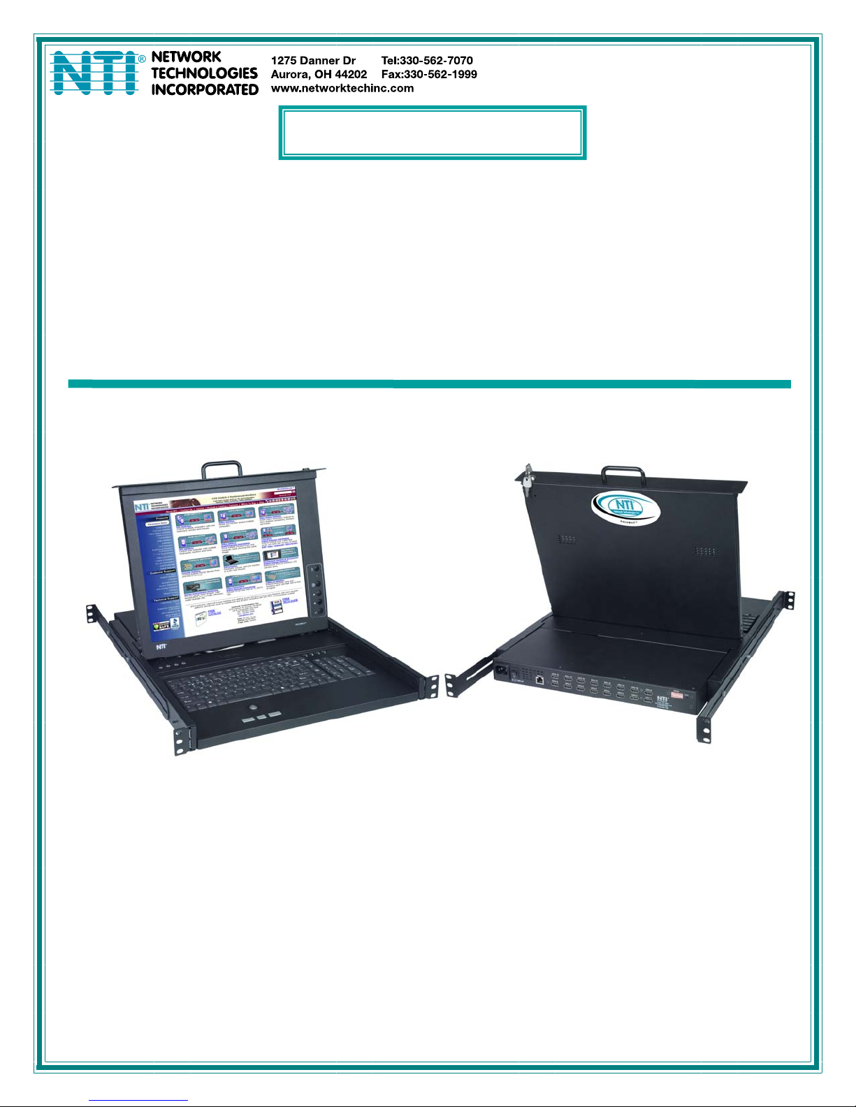
RACKMUX Series
RACKMUX-DS17-N-4/8/16DVIHD
DVI USB SUN KVM Drawer with USB KVM
Switch and DVI Video Support
Installation and Operation Manual
MAN082 Rev Date 7/6/2018
Page 2

TRADEMARK
RACKMUX is a registered trademark of Network Technologies Inc in the U.S. and other countries.
COPYRIGHT
Copyright © 2008-2018 by Network Technologies Inc. All rights reserved. No part of this publication may be reproduced, stored
in a retrieval system, or transmitted, in any form or by any means, electronic, mechanical, photocopying, recording, or otherwise,
without the prior written consent of Network Technologies Inc, 1275 Danner Drive, Aurora, Ohio 44202.
CHANGES
The material in this guide is for information only and is subject to change without notice. Network Technologies Inc reserves the
right to make changes in the product design without reservation and without notification to its users.
Page 3

TABLE OF CONTENTS
INTRODUCTION.............................................................................................................................................................1
Models Available.......................................................................................................................................................1
Types of CPUs Supported........................................................................................................................................1
Features....................................................................................................................................................................1
Option .......................................................................................................................................................................1
MATERIALS....................................................................................................................................................................2
FEATURES AND FUNCTIONS.......................................................................................................................................3
INSTALLATION...............................................................................................................................................................4
Rack Mounting Instructions .........................................................................................................................................4
Extension Bracket Method........................................................................................................................................4
One-Man Installation Method....................................................................................................................................5
Optional Telco 2-Post Mounting ...............................................................................................................................8
Connect The Cables....................................................................................................................................................9
RS232 Connection..................................................................................................................................................10
Power-Up Sequence..................................................................................................................................................10
USING THE UNIMUX....................................................................................................................................................11
Front Panel Control....................................................................................................................................................11
Keyboard Control.......................................................................................................................................................11
Command Mode........................................................................................................................................................11
Scan Mode..............................................................................................................................................................12
Broadcast Mode......................................................................................................................................................12
Normal Mode ..........................................................................................................................................................12
No Sun Sleep Mode................................................................................................................................................13
Select Country\Language Code..............................................................................................................................13
RS232 CONTROL.........................................................................................................................................................14
RS232 Connections and Configuration.....................................................................................................................14
Remote Connection................................................................................................................................................14
Baud Rate...............................................................................................................................................................14
Unit Address and Loop Back..................................................................................................................................15
Command Protocol.................................................................................................................................................16
NTI Switch Control Program For Windows 9X, NT, 2000, XP, And Vista.................................................................18
SerTest- RS232 Interface Test Program...................................................................................................................18
Main Options...........................................................................................................................................................18
DISPLAY FUNCTIONS.................................................................................................................................................20
Standard Controls......................................................................................................................................................20
OSD Control Menu ....................................................................................................................................................21
OSD Main Menu .....................................................................................................................................................21
Brightness/Contrast Menu......................................................................................................................................21
Setup Menu.............................................................................................................................................................22
KEYBOARDS................................................................................................................................................................23
Keyboard Configuration.............................................................................................................................................23
TROUBLESHOOTING..................................................................................................................................................24
RACKMUX SPECIFICATIONS .....................................................................................................................................25
General Specs...........................................................................................................................................................25
LCD – 17” ..................................................................................................................................................................25
Display Controller: DVI ..............................................................................................................................................25
OSD Control Board....................................................................................................................................................25
Keyboard....................................................................................................................................................................25
Trackball ....................................................................................................................................................................26
Touchpad...................................................................................................................................................................26
INDEX............................................................................................................................................................................26
WARRANTY INFORMATION........................................................................................................................................26
Page 4

TABLE OF FIGURES
Figure 1- Mount RACKMUX to a standard rack.................................................................................................................................4
Figure 2- Adjustable rail depth...........................................................................................................................................................5
Figure 3- Install cage nuts..................................................................................................................................................................5
Figure 4- Install rail assemblies .........................................................................................................................................................6
Figure 5- Adjust distance between rails.............................................................................................................................................6
Figure 6- Slide the RACKMUX into the rails ......................................................................................................................................7
Figure 7- Secure the RACKMUX.......................................................................................................................................................7
Figure 8- Position RACKMUX with clearance to open.......................................................................................................................8
Figure 9- Mount to Telco post with optional mounting brackets.........................................................................................................8
Figure 3- Connect each CPU.............................................................................................................................................................9
Figure 4- Connect the power cord .....................................................................................................................................................9
Figure 5- Connect RS232 control terminal.......................................................................................................................................10
Figure 6- CPU Select switches, status LEDs and Mode LEDs ........................................................................................................11
Figure 7- Country\Language Codes for international SUN keyboards.............................................................................................13
Figure 8- RS232 DIP switches .........................................................................................................................................................14
Figure 9- RS232 connection with Matrix-Y-1 cable..........................................................................................................................15
Figure 10- Pinout of Matrix-Y-1 cable..............................................................................................................................................16
Figure 11- RS232 Communication Illustrated..................................................................................................................................16
Figure 12- OSD Controls .................................................................................................................................................................20
Figure 13- U.S. (English) SUN Keyboard with numeric keypad.......................................................................................................23
Figure 14- French SUN Keyboard with numeric keypad..................................................................................................................23
Page 5
NTI RACKMUX KVM Drawer with UNIMUX Switch
INTRODUCTION
The RACKMUX-DS17-N(T)-xDVIHD is a KVM Drawer with USB KVM Switch (RACKMUX) that combines a rackmount 17” TFT /
LCD DVI monitor, SUN keyboard, trackball or touch pad mouse, and USB KVM switch (UNIMUX) in a space-saving 1RU industrial
strength drawer. The RACKMUX is equipped with a built-in switch function, which allows control of up to sixteen DVI -enabled
USB computers with a single SUN keyboard, trackball or touchpad and DVI monitor. When access to a server rack is needed, the
drawer can be pulled out and the display lifted up like a notebook com puter, revealing the SUN keyboard and trackball or
touchpad. When the drawer is not in use, the display can be folded forward and down so the 1RU drawer can be pushed into the
cabinet easily and smoothly, helping to organize and streamline busy server rooms.
The onboard USB KVM switch allows access to any DVI-enabled Windows, MAC, or SUN USB CPUs from one DVI monitor, USB
keyboard and USB mouse (up to 16 CPUs). Internal microprocessor circuitry allows all USB CPUs to be booted simultaneousl y
without keyboard error. Port selection is accomplished through switches on the keyboard tray or keyboard comman ds.
Models Available
RACKMUX-DS17-NT-4DVIHD - KVM Drawer with 17" TFT/LCD DVI monitor, trackball mouse and 4-port UNIMUX
RACKMUX-DS17-N-4DVIHD - KVM Drawer with 17" TFT/LCD DVI monitor, touchpad mouse and 4-port UNIMUX
RACKMUX-DS17-NT-8DVIHD - KVM Drawer with 17" TFT/LCD DVI monitor trackball mouse and 8-port UNIMUX
RACKMUX-DS17-N-8DVIHD - KVM Drawer with 17" TFT/LCD DVI monitor, touchpad mouse and 8-port UNIMUX
RACKMUX-DS17-NT-16DVIHD - KVM Drawer with 17" TFT/LCD DVI monitor, trackball mouse and 16-port UNIMUX
RACKMUX-DS17-N-16DVIHD - KVM Drawer with 17" TFT/LCD DVI monitor, touchpad mouse and 16-port UNIMUX
Types of CPUs Supported
Any DVI-enabled USB CPU supporting USB version 1.0 or above including:
USB WINxx
USB MAC
USB SUN
Features
Entire unit is only 1RU (1.75") high
High-quality metal construction (ideal for most industrial and commercial settings)
17" Rack Mount LCD Monitor features a wide viewing angle
1280x1024 resolution
A forward-folding 17” TFT LCD DVI monitor
Includes rack mount kit suitable for SUN and most EIA 19" racks
Fits varying rack depths from 22” to 39” deep via adjustable mounting brackets
DVI Video Compatible
Powered by 110 or 220VAC, 50 or 60Hz with country-specific line cord
Auto shut-OFF switch: Turns OFF the power to the monitor when the LCD is in a folded-closed position
Standard 3-button touchpad
Added security with a drawer lock to prevent unwanted access
Locking rails to prevent movement of the drawer when fully extended
Multi-language support including: US(English), UK(English), German, French, Italian, and Spanish
Option
Rackmounting kit for two-post Telco rack - order RL-T15-TEL
1
Page 6
NTI RACKMUX KVM Drawer with UNIMUX Switch
MATERIALS
Materials supplied with this kit:
NTI RACKMUX-DS17-N(T)-xDVIHD KVM Drawer with USB KVM Switch (where x= 4,8 or 16)
Line cord, country specific
Set of keys for keylock
2 Rear Mounting Brackets w/ 4 nuts
8pcs #10-32x3/4” screws and cage nuts for mounting to a rack
URL slip with address to pdf of this manual
1- DB9 Female-to-RJ45 Female adapter
1- 5 foot RJ45-to-RJ45 CAT5 patch cable
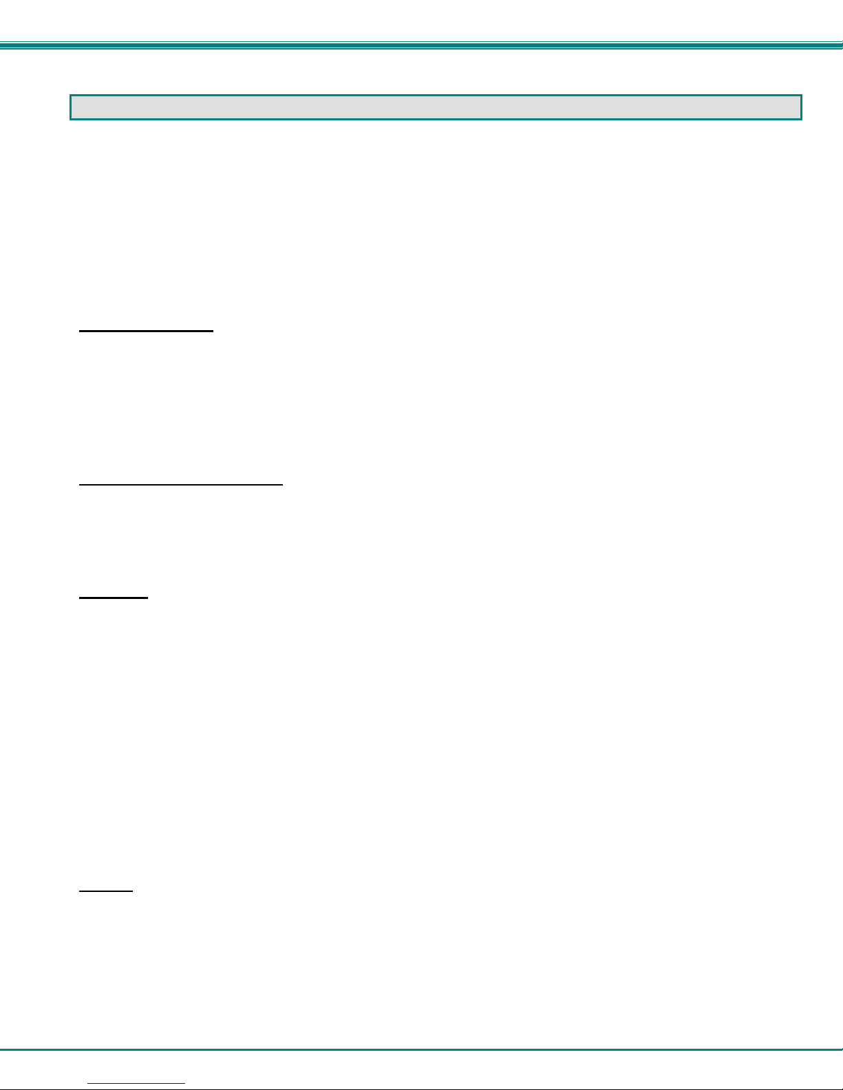
Materials Not supplied but REQUIRED:
USB-DHEXT-xx-MM cable for each CPU being connected to the switch- for DVI monitor, USB keyboard, and USB mouse
support- available in 3, 6,10, and 15 foot lengths
where:
xx is the length of the cable in feet
MM indicates male-to-male connector
Cables can be purchased from Network Technologies Inc by calling (800) 742-8324 (800-RGB-TECH) in the US and Canada or
(330) 562-7070 (worldwide).
DVI-D-Male
USB Type A
Male
DVI-D-Male
Single Link
USBType A Male
USB-DHEXT-xx-MM
HDMI Type A Male
(3,6,10 and 15 foot cables available)
HDMI Type A
Male
2
Page 7
NTI RACKMUX KVM Drawer with UNIMUX Switch
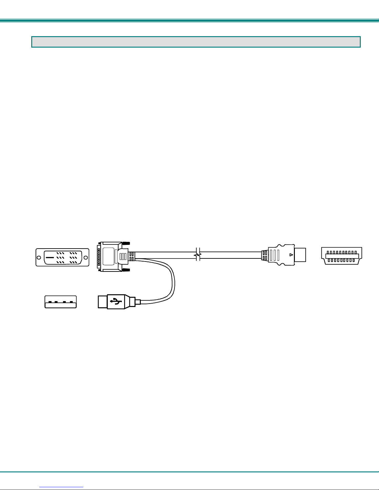
Front View
RACKMUX-DS17-NT-8DVIHD
15
14
13
17
16
87654321
11
12
Scan
18
1
2
3
4
5
6
1
7
CommandBroadcast
19
20
21
A
8
22
Compose
9
23
10
DDC
ON
8
1
VIDEO 1VIDEO 2VIDEO 3VIDEO 4VIDEO 5VIDEO 6VIDEO 7VIDEO 8
24
Rear View
RACKMUX-DS17-NT-8DVIHD
FEATURES AND FUNCTIONS
1. Power Button- press to turn the LCD monitor ON and OFF
2. Power LED- Indicates operation status
Green = Power-ON, Video Input Signal OK
Red = Suspend / Stand-by, or no Video Input Signal
3. Menu Button- press to turn ON the OSD menu
4. Up Arrow Button- press to move the cursor in the OSD menu up
5. Down Arrow Button- press to move the cursor in the OSD menu down
6. Select Button- press to select a menu item (when OSD menu is ON) or press to auto adjust the video quality (when OSD
menu is OFF)
7. NumLock LED- illuminates when the Num Lock is ON
8. CapsLock LED- illuminates when Caps Lock is ON
9. Scroll Lock LED- illuminates when the Scroll Lock keyboard feature is ON
10. Compose LED- illuminates when the Compose ke yboard feature is ON
11. Keylock- to prevent unauthorized use of the RACKMUX
12. 3-button Touch Pad or Trackball- for controlling mouse movements on the monitor and controlling the computer
13. Keyboard- for manual data entry and computer control
14. Auto Shut-OFF- switch automatically shuts OFF the LCD display when the monitor is folded down
15. LCD Display- for viewing the vide o signal from the connected CPU
16. CPU Select Switch- push to manually switch to a specific CPU or change the switch operating mode
17. CPU Status LED- for visual indication of connection between the user and a specific CPU
18. Mode Status LEDs- for visual indication of switch operating mode
19. IEC Connector w/Built-in 2A 240VAC Replaceable Fuse- for attachment of the AC power cord to power the RACKMUX
drawer
20. Power Switch- to pow er the RACKMUX ON/OFF
21. RS232- RJ45 connector- for attachment of an RS232 control cable
22. CPU x- HDMI Type A female connectors- for connecting USB-DHEXT-xx-MM cables from CPUs
23. RS232 DIP Switches- for controlling the baud rate of the RACKMUX for RS232 communic ation
24. DDC- recessed button used to reset DDC information between the RACKMUX and the connected CPU
3
Page 8
NTI RACKMUX KVM Drawer with UNIMUX Switch
s
INSTALLATION
Rack Mounting Instructions
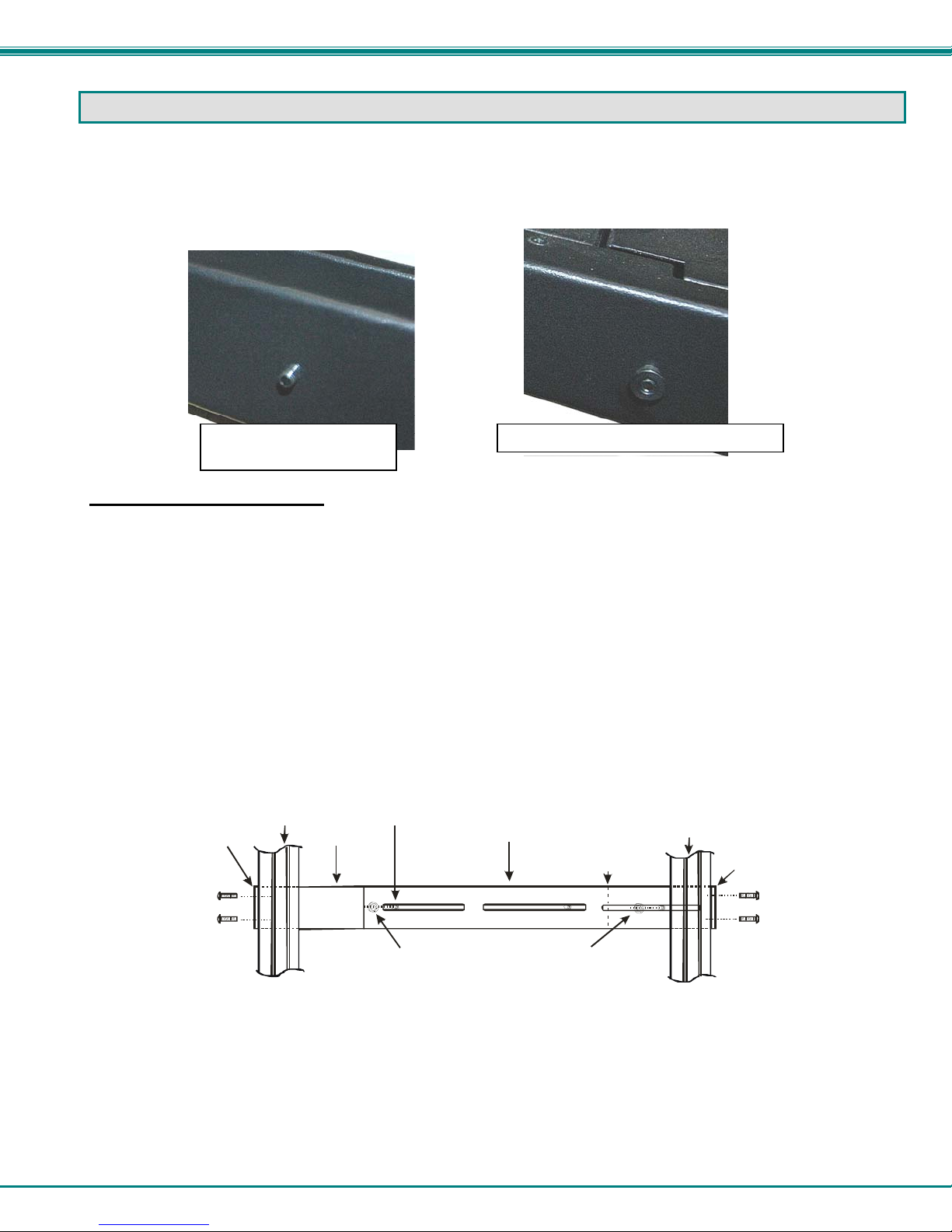
The RACKMUX was designed to be mounted to a rack and includes mounting flanges to make attachment easy. The rails that
are provided for rack mounting will either be empty studs for insertion through slots in a rear extension bracket, or rail guides for
one-man installation to a front and rear bracket set. Depending upon the method provided, install your RACKMUX accordi ng to
the instructions below.
Stud for mount to
extension bracket
Guide for one-man installation method
Extension Bracket Method
1. Determine the mounting height in the rack for the drawer. It should be a height comfortable to use the keyboard and see the
LCD display. Mark holes in each of the 4 corner cabinet rails at points all level with each other.
2. Secure the rear brackets to the rear rack cabinet rails. Apply the top screws (supplied) for each bracket to the holes marked in
step 1.
3. Lift the keyboard into position and line the studs on the left and right sides up with the slotted openings in the rear bracket.
Apply the nuts (supplied) to the studs but do not tighten the nuts yet.
FYI: There are 4 mounting studs provided on each side of the RACKMUX. Depending on the depth of the rack and
distance apart of the cabinet rails, the position of the rear bracket may make all 4 studs available for use. In this case,
apply the 2 nuts to the studs furthest apart from each other on each side.
4. Slide the drawer in until the top holes in the front bracket flanges line up with the holes marked in step 1. Secure the front
brackets on the drawer to the front cabinet rails with two screws per bracket. Be sure to tighten the screws securely. Then
tighten the nuts applied in step 3.
5. Apply one more screw to each of the rear brackets to finish.
Front brac ket
flange on dra wer
Figure 1- Mount RACKMUX to a standard rack
Secure bracket
to rail using two
screws and nuts
(supplied)
Front Cabinet
Rail
Drawer
Stud on dra wer
Rear bracket overlapping
drawer
(Rear edge
of dra w er)
Apply nuts ( supplie d) t o studs and
secure rear brackets to drawer.
Re ar Cabi ne t
Rail
Rear bracket
flange
Secure bracket
to rail using two
screws and nut
(supplied)
4
Page 9
NTI RACKMUX KVM Drawer with UNIMUX Switch
X
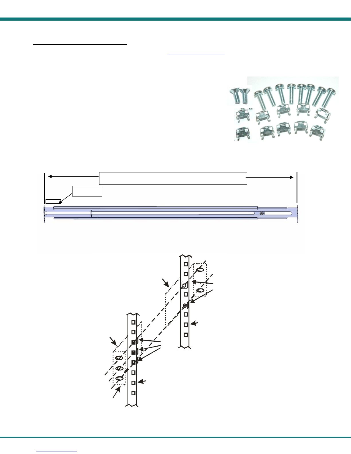
One-Man Installation Method
If you would like to see a video of this installation, see the “single-person-installation” video .
1. Locate and unpack the hardware bag. Your hardware bag will include all items neces s ary to install the specific RACKMUX
model (see the manual that accompanied your RACKMUX drawer), including the following hardware unique to the Single-Person
hardware installation:
10- #10-32 cage nut
2- #10-32 x 1/2” flat-head machine screw
8- #10-32 x 3/4” pan-head machine screw
To install the rails you will need only a tape measure and Phillips screwdriver.
2. Unpack the left and right rail assemblies. Each are labeled “Right Front” and “Left Front” to indicate their intended position and
orientation. Extend each rail assembly to the dimension required for your rack. Rail assemblies are adjustable to fit within a rack
between 24” and 40” in depth.
XXXX
Labeled
3. Install six #10-32 cage nuts at the front of the rack in positions where the RACKMUX will be mounted (three in each side).
Install four more cage nuts at the rear of the rack in positions straight across from the upper and lower cage nuts installed in front.
Rail assemblies are adjustable in length from 24” to 40”.
Extender Ra il
Rail Flange
Figure 2- Adjustable rail depth
Extender Ra il
Cage
Nuts
Rear Rack
Support
Cage
Nuts
Front R ack
Support
Figure 3- Install cage nuts
5
Page 10

NTI RACKMUX KVM Drawer with UNIMUX Switch
r
4. Install the right rail assembly. The end with the label “Right Front” mounts to the front rack support. Install only the center
screw through the rail flange to the rack support and cage nut using the #10-32 x 1/2” flat head machine scre w provided. (See
image below.) Do not tighten at this time. Install the left rail assembly in the same fashion. The end with the label “Left Front”
mounts to the front rack support.
5. Install two #10-32 x 3/4” pan-head screws in the rear of each rail assembly as shown below. Do not tighten at the time.
Install one flat
head screw in
the center in
each side at the
front
Figure 4- Install rail assemblies
6. Measure the distance between the inside of the rails at the front of the rack. Adjust the distance to 17-1/4” and tighten the flathead screws to the rail flanges securely.
Rack Front
Figure 5- Adjust distance between rails
Left Rail
Front Rack Supports
Install two
screws in each
side at the rea
Rack Rear
Right Rail
17-1/4"
6
Page 11

NTI RACKMUX KVM Drawer with UNIMUX Switch
7. Lineup the rail guides on the RACKMUX drawer with the slots in the front of the left and right rails and slide the drawer into the
rack. The rail guides should be positioned such that the wide lip of the guide is on the backside of the rail. Slide the drawer in
completely.
View of rail guide from the front of the rack support View of rail guide from the backside of the rail
Rail guides
Figure 6- Slide the RACKMUX into the rails
8. Apply four more #10-32 x 3/4” pan-head machine screws (two for each) through the holes in the drawer flanges, throug h the
holes in the left and right rails, into the cage nuts in the rack supports. Tighten each securely.
Apply two
more screws
on each side
There should
be a total of
six screws at
the front now.
Figure 7- Secure the RACKMUX
9. Tighten securely the four screws applied to the rear rail flanges in step 4.
Wide lip of rail guide
7
Page 12

NTI RACKMUX KVM Drawer with UNIMUX Switch
Note: To provide sufficient room for the LCD monitor to be opened to a p ro per viewing angle (a minimum 90 degree
position from the keyboard), ensure that all devices mounted above the RACKMUX extend no more than 1.75” from the
rack frame. (See Figure 8)
Figure 8- Position RACKMUX with clearance to open
"X" must be
less than 1.75"
for LCD to open
to full 90
90
Side View of RACKMUX
Server mounted
X
above RACKMUX
in the same rack
Optional Telco 2-Post Mounting
If the Telco 2-post mounting bracket kit (NTI# RL-T15-TEL) is to be used, secure the short and lo ng brackets to each side of the
drawer as shown in Figure 9. Apply 2 nuts (supplied) per bracket to secure the brackets to the drawer. Apply two #10-32x3/4”
screws (supplied) per bracket to the post at the desired height. Slots are provided in the brackets to make minor depth
adjustments easy. Be sure to properly tighten all nuts and screws before using the drawer.
Figure 9- Mount to Telco post with optional mounting brackets
8
Page 13

NTI RACKMUX KVM Drawer with UNIMUX Switch
Connect The Cables
FYI: It is not necessary to turn the CPUs or monitors OFF during this installation.
1. Connect each CPU to the UNIMUX switch using a USB-DHEXT-xx-MM (Required-not supplied) as shown in
250V,2A
Rear View of Windows USB CPU
Inpu t D evi ce Po r t
USB Type A Female
Video Port
DVI Female
Video Connector
Rear View of UNIMUX in RACKMUX-DS17-NT-16DVHD
RS232
ON
8
1
Mating Face of
RS232
USB Type A Male
Mating Face of
HDMI Type A
Video Connector
USB-DHEXT-xx-MM
(sold separately)
DVI Male
CPU 9CPU 10CPU 11CPU 12CPU 1 3CPU 14CPU 15CPU 16
CPU 1CPU 2CP U 3CPU 4CPU 5CPU 6CPU 7CP U 8
HDMI Type A Male
DDC
Figure 10.
2. Connect the power cord to the IEC power connector.
Rear View of UNIMUX in RACKMUX-DS17-NT-16DVIHD
RS232
250V,2A
Power cord
with IEC connector
Figure 10- Connect each CPU
CPU 9CPU 10CPU 11CPU 12CPU 13CPU 14CPU 15CPU 16
CPU 1CPU 2CPU 3CPU 4CPU 5CPU 6CPU 7CPU 8
Figure 11- Connect the power cord
9
RS232
ON
1
DDC
8
Page 14

NTI RACKMUX KVM Drawer with UNIMUX Switch
RS232 Connection
If RS232 control will be used, connect one end of the CAT5 patch cable (supplied) to the port labeled “RS232” on the rear of the
RACKMUX. Plug the other end of the CAT5 cable into the RJ45-to-DB9 adapter supplied and connect the adapter to the RS232
port on the control terminal. Follow the instruction under “RS232 Control” on page 14 for configuration and use of the RS232
control feature.
Figure 12- Connect RS232 control terminal
Power-Up Sequence
1. Using the key, unlock the drawer and slide the keyboard and LCD Display out far enough to raise the display to a comfortable
viewing angle.
2. Power ON the RACKMUX with the power switch located on the rear of the drawer.
3. Power ON the monitor with the power switch located on the monitor.
4. Adjust the screen's brightness and contrast with the controls also located on the monitor– as needed.
5. Power ON any attached CPUs.
FYI: The CPUs can be powered at any time, although if a CPU needs a keyboard and/or mouse at power-ON, it should be
powered after connecting to and powering-ON the RACKMUX.
10
Page 15

NTI RACKMUX KVM Drawer with UNIMUX Switch
USING THE UNIMUX
Once the RACKMUX is properly connected, the UNIMUX switch will enable a connection to be made between the attached CPUs
and the monitor, keyboard, and mouse.
The UNIMUX can be controlled by three methods:
front panel control using touch-switches and LEDs on the keyboard tray
keyboard control through Command Mode
RS232 control (see page 14)
Front Panel Control
There is a panel of numbered touch-switches and LEDs on the keyboard tray of the RACKMUX. There is one switch and
LED for each CPU the switch will connect the monitor and input devices to. Pressing any touch-switch will connect the
corresponding CPU to the monitor and input devices.
Holding down any touch-switch for more than 2 seconds will cause the UNIMUX to cycle through all modes of operation
including COMMAND, BROADCAST, SCAN, and NORMAL (described in "Command Mode" below). The three MODE LEDs on
the panel indicate which mode is selected. Release the touch-switch when the LEDs indicate the desired mode. When no mode
LEDs are illuminated the user is in Normal Mode controlling directly the CPU to which the user is con nected through the UNIMUX.
Scan
87654321
CommandBroadcast
Figure 13- CPU Select switches, status LEDs and Mode LEDs
Keyboard Control
Keyboard control of the UNIMUX switch is achieved using Command Mode - operated using the keyboard . By pressing
<Ctrl> + < ` > (accent/tilde key), the user can enter Command Mode. Once in Command Mode, typing a series of commands
will cause the UNIMUX switch to connect the user to any one CPU connected to the switch. Pressing the <Esc> key will exit
Command Mode. The following instruction describes how to use the menus to operate the UNIMUX s witch.
Command Mode
In order to control the UNIMUX with the keyboard connected, Command Mode must be enabled. To enter Command Mode from
the keyboard:
When the COMMAND LED is illuminated, all 3 LEDs on the keyboard will illuminate (caps lock, scroll lock, and num lock) to
indicate that Command Mode is enabled and the following functions are available:
Basic Command Functions
Function: Keystroke:
Increment Port
Decrement Port
Press (simultaneously)
Ioror
D
Ctrl
(ACCENT/TILDE
+
~
KEY)
`
KEY SYMBOLS LEGEND:
or
PRESS EITHER KEY
(select the next
higher port
ex. 01 02)
(select the next
oror
lower port
ex. 02 01)
11
CHORDED SEQUEN CE- PRESS CONSECUTIVELY
AND KEEP KEYS PRESSED UNTIL ALL ARE PRESSED .
+
PRESS CONSECUTI VEL Y
-
Page 16

NTI RACKMUX KVM Drawer with UNIMUX Switch
Toggle Scan Mode
ON and OFF
Toggle Broadcast Mode
ON and OFF
Sets scan time-out
period for each port.
Selects a specific
port
Configure port to connect
To a MAC CPU
Configure port to connect
To a WINDOWS or SUN
CPU
Exit Command Mode
S
B
T
P
M
W
Esc
(The SCAN Mode LED will
also toggle ON and OFF)
(The Broadcast Mode LED
will toggle ON and OFF.)
(0-2)
+
+
-
-
x
(0-9)
x
x
x
-
-
x
+
x
+
FYI: The user must exit Command Mode to type to a CPU.
To exit Command Mode, either hold down any touch-switch on the
front panel for more than 2 seconds, OR press <ESC> on the
keyboard.
(0-9)
x
(0-9)
x
(Pxx would be P01, P02, etc.)
(xx= 01- 8 <M> + <0> + < 1> will enable function on Port 1
<M> + <0> + <4> will enable function on Port 4. Keyboard
LED's will flash once to confirm command. )
(xx= 01-8 <W> + <0> + <1> will disable function on Port 1
<W> + <0> + <4> will disable function on Port 4. Keyboard
LED's will flash once to confirm command. )
(0-9)
-
x
(xxx from 00 2 t o 255. ie. T002
would set the time-out period
for 2 seconds)
Scan Mode
To activate Scan Mode press <S> while in Command Mode menu. When in Scan Mode the switch scans to each port with a CPU
powered-ON. (The SCAN LED on the front panel will illuminate and remain ON while in Scan Mode. ) The port with the CPU
powered-ON remains active while in use until it becomes idle for the configured dwell time (default time-out period is 5 secon ds)
before switching to the next powered-ON CPU port. See Command Mode section above for configurin g the scan dwell time.
Note: The keyboard and mouse must remain idle for the full scan dwell time before the switch selects the next active
port.
To begin scanning, press <Esc> to exit Command Mode.
To deactivate Scan Mode press <S> again while in Command Mode.
Broadcast Mode
To activate Broadcast Mode press <B> while in Command Mode. Broadcast Mode enables the user to type characters to all
powered-ON CPUs simultaneously.
Note: The user must type somewhat slowly (less than 20 wpm) when in Broadcast Mode and cannot use the
<Backspace> key.
To begin broadcasting, press <Esc> to exit Command Mode.
To deactivate Broadcast Mode press <B> again while in Command Mode.
Normal Mode
When the Broadcast, Scan, and Command LEDs are all OFF the user is in Normal Mode, controlling the CPU to which the user is
connected through the UNIMUX.
12
Page 17

NTI RACKMUX KVM Drawer with UNIMUX Switch
No Sun Sleep Mode
Note: It is necessary to configure a Sun CPU (most versions) such that the Sleep Mode is not enabled. If the Sun CPU
goes into Sleep Mode either automatically or manually, the user must reboot the Sun CPU in order to resume use of the
Sun CPU.
To disable the Sleep Mode, perform the following steps:
1. Select "Power Manager"
2. Look for "Device Idle Time Before Power Saving Starts"
3. Select "Always ON"
4. Look for "Override Device Idle Time For:"
5. Make sure neither "Monitors" nor "Disks" are selected.
Select Country\Language Code
It is possible to configure the UNIMUX to emulate a specific international Sun keyboard regardless of what actual keyboard is
connected. This is recommended when the CPU needs the layout code (i.e. a SUN CPU) and the keyboard doesn't have an
explicit layout code (i.e. some Windows keyboards). To do this, manually set the UNIMUX to indicate th e international keyboard
identification number to the CPU using the following procedure;
1. Enter Command Mode
2. Type Lxx, where xx is the number from the list below that corresponds to the desired country code
3. Exit Command Mode
Note: If any SUN CPUs are connected to the UNIMUX, they must be rebooted. Keyboard configuration is only read by
SUN CPUs on startup.
Country\Language Codes
00 Auto Detect 13 International (ISO) 26 Swedish
01 Arabic 14 Italian 27 Swiss/French
02 Belgian 15 Japan (Katakana) 28 Swiss/German
03 Canadian-
Bilingual
04 Canadian-French 17 Latin American 30 Taiwan
05 Czech Republic 18 Netherlands/Dutch 31 Turkish
06 Danish 19 Norwegian 32 UK
07 Finnish 20 Persian (Farsi) 33 US
08 French 21 Poland 34 Yugoslavia
09 German 22 Portuguese
10 Greek 23 Russia
11 Hebrew 24 Slovakia
12 Hungary 25 Spanish
16 Korean 29 Switzerland
Figure 14- Country\Language Codes for international SUN keyboards
13
Page 18

NTI RACKMUX KVM Drawer with UNIMUX Switch
RS232 CONTROL
RS232 enables the UNIMUX to be remotely controlled via RS232. To control the UNIMUX via RS232 the user has three options:
write a program that runs on a PC using the Command Protocol (page 16)
use the NTI Switch Control Program (page 18)
use the SerTest program (page 18)
RS232 Connections and Configuration
Remote Connection
The RS232 Interface is designed to meet the RS232C standard and can be controlled from any CPU or other contro ller with an
RS232 communications port. The pin-out for the RJ45 connector on the unit is as follows:
RS232 (RJ45) CONNECTOR
PIN SIGNAL FUNCTION
1 - No connection
2 - No connection
3 RX+ Receive data (TXD at host)
4 GND Ground
5 - No connection
6 TX+ Transmit data (RXD at host)
7 - No connection
8 - No connection
A 5 foot patch cable and RJ45-to-DB9 adapter have been provided for connection to most CPUs (see page 10).
Baud Rate
The baud rate can be changed by powering down the unit, changing the 8-position RS232 DIP switch on the rear of the UNIMUX,
and then powering back up. This table shows how to set the baud rate. (Figure 15 shows switches in their factory-default position.)
DIP
SWITCH
3 2
OFF OFF 2400
OFF ON 9600 (default)
ON OFF 19200
ON ON 38400
Figure 15- RS232 DIP switches
BAUD RATE
14
ON
1
RS232
8
Page 19

NTI RACKMUX KVM Drawer with UNIMUX Switch
Unit Address and Loop Back
To allow multiple units to be controlled from a single CPU serial port, the RS232 con trol interface is designed to allow "daisy
chaining" up to 7 units. By setting the appropriate RS232 DIP switches, each unit can be given a unique address (1-7). Then the
unit will only respond to commands on the bus if its address is embedded i n the command. Us e the follo wing table t o set the unit
address.
DIP SWITCH UNIT ADDRESS
8 7 6 5
OFF OFF OFF OFF 0 (not valid)
OFF OFF OFF ON 1 (default)
OFF OFF ON OFF 2
OFF OFF ON ON 3
OFF ON OFF OFF 4
OFF ON OFF ON 5
OFF ON ON OFF 6
OFF ON ON ON 7
Note: Pin 4 on the RS232 DIP switch is not used.
In order to connect multiple switches (up to 7) with RS232 connections to the same CPU, an NTI Matrix-Y-1 cable must be used.
Connect the Matrix-Y-1 cable (sold separately) between the RJ45-to-DB9 serial adapter (supplied) and the CPU as sh own in
Figure 16.
CPU
Figure 16- RS232 connection with Matrix-Y-1 cable
RS232
Serial Port
RJ45
TO DB9
SERIAL
ADAPTER
First Unit
Matrix-Y-1
Matrix-Y-1 Matrix-Y-1
RJ45
TO DB9
SERIAL
ADAPTER
CAT5 CABLE CAT5 CABLE CAT5 CABLE
RS232
NTI
SWITCH
RS232
NTI
SWITCH
Second Unit Last Unit
Note: The "loop back" RS232 DIP switch (RS232 DIP
switch 1) should be ON for each unit in the chain.
Note: The maximum combined
RJ45
TO DB9
SERIAL
RS232 cable length between the
CPU and any NTI switch cannot
exceed 15 feet.
ADAPTER
RS232
NTI
SWITCH
15
Page 20

NTI RACKMUX KVM Drawer with UNIMUX Switch
Figure 17- Pinout of Matrix-Y-1 cable
Wiring Schematic of Matrix-Y-1 cable
9D Female9D Male 9D Male
(Unit #1)
23
33
555
(Source)
(Unit #2)
22
7
Jumper
8
1
Jumpers
4
6
Not connected to
source connector
Command Protocol
RS232 commands supported by the unit are defined below. All command strings should be terminated with a <CR> (carriage
return). When a command is sent, the entire string is echoed back along with a response from the addressed unit as shown in the
command definitions. All characters in the command string should be upper case, and all numbers below 10 should have a
leading 0 (ex: 1 = 01). As command strings are sent, the inner character delay cannot exceed 500 milliseconds.
Figure 18- RS232 Communication Illustrated
Note: To use this command protocol, the user is required to write a program that will send an entire command string all
at once, not character by character. Programs that send one character at a time (such as HyperTerminal) cannot be used
to control the UNIMUX. Alternatively, the user may use the NTI Switch Control Program or SerTest to control the
UNIMUX via RS232 (see page 18).
(COMMAND SENT)
(RESPONSE RECEIVED)
CPU
CS 01,01,03<CR>
CS 01,01,03<CR>
* <CR>
RS232
RS232
SWITCH AT UNIT ADDRESS 01
(COMMAND RECEIVED)
CS 01,01,03<CR>
(ECHO)
CS 01,01,03<CR>
(RESPOND)
* <CR>
16
Page 21

NTI RACKMUX KVM Drawer with UNIMUX Switch
Legend: (All numbers must be two digits)
SW : Switch (01-7) (Unit Address)
OP : Output (User) Port (01)
BR : Baud R ate (12 =1200, 24=2400, 48=4800, 96=9600 baud)
IP : Input (CPU) Port (01-MAXINPUTS)
<CR> : Carriage Return (Hex 0xD)
Note: For units with one output (user) port, use 01 for the output selection.
Command Definitions
Command String Good Response Description
CS SW,IP,OP *<CR> Connect Output (User) Port To specific Input (CPU) Port
RO SW,OP *<CR>IP<CR> Read Connection For Output (User) Port to Input (CPU) Port
CB 00,BR None Change Baud Rate For All Switches (BR=12 (1200), 24 (2400),
RS SW *<CR> Internal Reset
RU SW *<CR>IP,OP<CR> Read Unit Size
SS SW,00 *<CR> Disable Autostatus feature (see below)
SS SW,01 *<CR> Enable Autostatus feature (see below)
GO SW,OP *<CR>go SW,OP:IP<CR> Read connection of a Output (User) Port to Input (CPU) Port
GM SW,00 *<CR>go OP,IP (all ports)<CR> Read connection matrix of all Output (User) ports
If the first field is not a known command (as listed above) or SW field is different from the unit address programmed at the DIP
switch (page 15), the command will be ignored. If the SW field corresponds to the unit address, but if the syntax is wrong after
this field, the switch will answer with a bad response ?<CR>.
Syntax example:
CS 01,05,01<CR> (insert the space and commas as shown)
which means “At the switch with unit address 01, connect CPU port 05 to user port 01”
The switch will answer with:
<CR>
The HEX code representation of example above is:
Byte 1 Byte 2 Byte 3 Byte 4 Byte 5 Byte 6 Byte 7 Byte 8 Byte 9
‘C’
(0x43)
‘S’
(0x53)
Space
(0x20)
Byte 10 Byte 11 Byte 12
Input –1st digit
(0x30)
Response:
Input –2nd digit
(0x31)
Byte 1 Byte 2
‘’
(0x2A)
<CR>
(0x0D)
Autostatus
When Autostatus is enabled, any output (user) -to-input (CPU) connection change in the UNIMUX will cause an Autostatus
message to be sent via RS232 to the administrator. The format of the message would be "pc SW,OP:IP<CR>"
Example of an Autostatus message:
pc 01,01:04<CR>
which means "At the switch with unit address 01, the output (User) (01) has changed connection to input (CPU) port 04."
Note: An Autostatus message to the administrator will be delayed by any RS232 traffic being received by the switch
from the administrator.
By default, Autostatus is disabled and must be manually enabled.
Switch – 1st digit
(0x30)
<CR>
(0x0D)
48 (4800), 96 (9600) baud)- see “Note” below
(different response format than RO command)
Switch – 2nd digit
(0x31)
17
Output – 1st digit
‘,’
(0x2C)
(0x30)
Output – 2nd digit
(0x35)
Note: a change in the baud rate using
RS232 will only be effective until the
UNIMUX is power- cycled. The DIP
switch positions (page 10) will
determine the set baud rate each
time the UNIMUX is powered ON.
‘,’
(0x2C)
Page 22

NTI RACKMUX KVM Drawer with UNIMUX Switch
NTI Switch Control Program For Windows 9X, NT, 2000, XP, And Vista
The NTI Switch Control Program is an easy and powerful graphical program that controls NTI switches through an RS232
interface. The NTI Switch Control Program can be downloaded from http://www.networktechinc.com/srvsw-usb-dvi.html.
To install the NTI Switch Control Program after downloading
1. Locate the Setup.exe in the directory the program was downloaded to and double-click on it
2. Follow the instructions on the screen
Note: In order to use the NTI Switch Control Program to control the UNIMUX, the UNIMUX RS232 port must be set at a
baud rate of 9600 bps (see page 14).
The NTI Switch Control Program performs best on monitors set to a screen resolution of at least 800 X 600. Instruction for using
the NTI Switch Control Program is available by opening "MSCP Help" in the "NTI" program group once the program has been
installed and is open on the screen.
To open "MSCP Help" from the Windows desktop
1. Click on START
2. Click on PROGRAMS
3. Click on NTI
4. Click on MSCP Help
SerTest- RS232 Interface Test Program
This software allows a user to test the functions of an NTI server switch, matrix switch or Multi-user/Multi-platform/Single-user
switch RS232 interface. The SerTest program is automatically loaded when installing the NTI Switch Control Program as
described above. The SerTest program, located in the NTI program group, generates a main me nu with the 4 selections
described below:
Main Options
Switch Operations
Ethernet Operations
Setup Options
About SerTest
If Matrix Operations is selected, the following menu is displayed:
SWITCH OPERATIONS
1) Reset Unit
- send a reset command to the switch
- the current unit address is displayed in parentheses
2) Reset All Units
- send an internal reset command to all switches
3) Connect Output/User to an Input/CPU
- connect an output to an input
4) Connect All Outputs/Users to an Input/CPU (not applicable to this model)
- connect all outputs to an input
5) Connect Audio Output/User to an Input/CPU (not applicable to this model)
- connect an output to an input
6) Connect All Audio Outputs/Users to an Input/CPU (not applicable to this model)
- connect all outputs to an input
7) Change Mute Status for Audio Output/User (not applicable to this model)
- mute or un-mute the Audio port output
- send commands to the unit.
- set Ethernet connection variables (not applicable to this model)
- set COM port, baud rate, and unit address
- display the program version
18
Page 23

NTI RACKMUX KVM Drawer with UNIMUX Switch
8) Change Volume for Audio Output/User (not applicable to this model)
- change Audio port output volume
9) Read Connection for Output/User
- read what input is connected to the specified output
a) Read Connection for Audio Output/User (not applicable to this model)
- read what input is connected to the specified output
b) Read Mute Status and Volume for Audio Output/User (not applicable to this model)
- read the volume and the mute status of the specified output
c) Read Unit Size
- read the switch size (number of inputs and outputs)
d) Read Unit Version/Revision String (not supported by this model)
- read a string containing the switch version, type, and size
e) Save I/O Connections into Unit Memory (not applicable to this model)
- save the connections into switch memory bank
f) Restore I/O Connections from Unit Memory (not applicable to this model)
- restore the connections from switch memory bank
g) Save All Units I/O Connections into Units Memory (not applicable to this model)
- save the connections into switch memory bank, command for all switches
h) Restore All Units I/O Connections from Units Memory (not applicable to this model)
- restore the connections from switch memory bank, command for all switches
i) Change All Units Baud Rate (9600/COM1)
- change RS-232 Baud rate of all switches
- the current baud rate and serial port are displayed in parentheses
Note: a change in the baud rate using SERTEST will only be effective until the UNIMUX is power- cycled. The DIP switch
positions (page 14) will determine the set baud rate each time the UNIMUX is powered ON.
ETHERNET OPERATIONS (not applicable to this model)
SETUP OPTIONS
1) select Com port current: (COM1:)
- select PC serial port
- the current PC serial port is displayed in parentheses
2) select Baud rate current: (9600)
- select PC serial port baud rate
- the current baud rate is displayed in parentheses
Note: a change in the baud rate using SERTEST will only be effective until the UNIMUX is power- cycled. The DIP switch
positions (page 14) will determine the set baud rate each time the UNIMUX is powered ON.
3) set unit Address current: (1)
- select the unit address of the switch to be connected to by this program
- the current address is displayed in parentheses
For any selection that requires user input, the user is prompted. When commands are sent to the UNIMUX, the command string
and UNIMUX responses are echoed to the screen. All commands generated by the program are formatted according to the
information provided in sections above. If any transmission problems are detected, an error message is displayed.
Press <Esc> or <Enter> to back out to the main menu and press again to exit.
19
Page 24

NTI RACKMUX KVM Drawer with UNIMUX Switch
DISPLAY FUNCTIONS
An NTI RACKMUX with a 17” monitor supports resolutions up to SXGA (1280x1024) with a refresh rate at between 55 and 76Hz.
The quality of the image on the LCD monitor is adjustable using an On Screen Display (OSD) menu using the control buttons on
the RACKMUX.
Standard Controls
The RACKMUX has 5 standard control buttons and a power LED. The 5 standard co ntrol buttons operate as follows:
The Power button turns the RACKMUX LCD and backlight ON and OFF as desired.
The Power LED located immediately below the Power button is a dual color
LED. It will illuminate with a green color when the RACKMUX is powered
ON and working properly. It will illuminate with a red color if the RACKMUX
is powered ON but there is no input signal detected.
The Menu button is used to bring up the OSD menu where the various
settings of the LCD display can be adjusted. Once the OSD screen is
displayed, the Menu button is used to make selections within the menus.
See "OSD Control Menu" (below) for more on LCD display settings.
The Up and Down Arrow buttons are used to navigate through the menus.
Move the cursor up or down as desired to highlight an item for selection.
Once an item is highlighted, pressing the Menu button will select it.
Power
ON/OFF
Power LED
Menu
Up Arrow
Down Arrow
Select/
Auto Adjust
Controls for the
OSD Menus
Note: When the OSD Menu is OFF, the Up Arrow is used to toggle
between a “PC” (VGA) and “Digital” (DVI) input source.
The Select button is used to make selections within the OSD menus when the OSD menu is ON. When the OSD menu is
OFF, the Select button will act as an Auto Adjust button to keep the user from having to use the menus to adjust the quality
of the image on the monitor.
Note: In order to display the OSD Menu, the RACKMUX must first be connected to a video source (see “Connect the
Cables” – page 9).
Note: If the message “NO SIGNAL” appears when the monitor is powered-ON, the monitor may be set for a “PC” (VGA)
input source. Press the Up Arrow button on the monitor to toggle the monitor input source setting to “Digital” (DVI).
Figure 19- OSD Controls
20
Page 25

NTI RACKMUX KVM Drawer with UNIMUX Switch
OSD Control Menu
The OSD (On Screen Display) Menu enables the user to select the desired characteristics of the LCD di splay. To activate the
OSD Menu, press the Menu button (above). To turn the Menu back OFF, either select "EXIT" from the main menu or just wait
10-60 seconds and it will automatically be cleared from the screen. Any changes made before exiting the menu will be saved.
OSD Main Menu
Note: In order to display the OSD Menu, the RACKMUX must first be connected to a video source (see “Connect to a
CPU” – page 9).
Note: If menu does not appear when the Menu button is pressed, the monitor may be set for a “PC” (VGA) input so u rce.
Press the Up Arrow button on the monitor to switch it to a “Digital” (DVI) input source.
Selection Purpose Range
Brightness/Contrast Increase/decrease panel brightness/contrast level 1-100
Setup
Exit Exit from the OSD control menu
Control OSD Image position on screen
Set time OSD will stay on screen before auto shutoff
Select the language of the OSD menu
Select Input Source to display
0-4
10 to 60 seconds
English, Spanish, German, Italian, or French
Digital or PC (must be set to Digital)
Brightness/Contrast Menu
Selecting the Brightness/Contrast menu will bring up a screen in which the user can adjust the brightness and contrast levels of
the LCD display. Using the Up or Down arrows to navigate the menu, highlight either the BRIGHTNESS or CONTRAST sections
and press the Select button to choose the option to adjust. Then use the Up or Down Arrow to adjust the setting.
Select EXIT when finished to return to the Main Menu.
21
Page 26

NTI RACKMUX KVM Drawer with UNIMUX Switch
Setup Menu
Selecting the Setup menu will bring up a screen in which the user can adjust
OSD POSITION-the position of the OSD menus on the LCD display (positions 0-4)
OSD TIME-the length of time the user can be idle before the OSD menu automatically exits (adjustable from 10
to 60 seconds)
LANGUAGE-the language that the OSD menus will be presented in
INPUT SOURCE- the type of signal that is coming from the CPU, either Digital (DVI) or PC (VGA)
NOTE: As used on this RACKMUX, the INPUT SOURCE must be set
With the item highlighted, (use the Up or Down arrow to move between them), press the Select button to choose the option to
adjust. Then use the Up or Down Arrow to adjust the setting as needed. Select EXIT when finished to return to the Main
Menu.
to “Digital”.
OSD Image can be moved
to different points on the
display
22
Page 27

NTI RACKMUX KVM Drawer with UNIMUX Switch
KEYBOARDS
The keyboard on the RACKMUX is a standard Windows SUN keyboard with 17-key numeric keypad.
Note: The “Fn” key is not an active key on this keyboard.
Help
Esc
~
`
Tab
Caps Lock
Fn
F1
!
1
Shift
Ctrl Alt
Stop
F2
@
2
Q
Props Front Find Open
Again
F3
#
3
F5
F4
$
4
WE R
Paste
Copy
Cut
F6
F7
F8
F9
F10
%
5
T
&
^
7
6
YU I OP
(
*
9
8
ASDF GHJK L
<
ZXCVB
M
N
,
Compose
F11 F12
Undo
)
0
>
.
Alt
Graph
Compose
:
;
Prt Sc
SysRq
{
[
?
/
Insert
Scroll
Pause
Break
Lock
+
BackSpace
=
}
]
"
Enter
'
Shift
Delete
Home
Page
\
Up
Num
Lock
/
*
789
Home
Pg Up
-
+
Page
Down
End
456
123
Pg Dn
.
Del
Ins
End
0
Enter
Figure 20- U.S. (English) SUN Keyboard with numeric keypad
Annu
ler
0
a @
/
:
M
Alt
Graph
Compose
) ]
^
Impecr
Syst
:
!
Inser
Arret
Pause
Suppr
Attn
defil
+
= }
u
$
*
%
Entree
u
Fin
Ver
Num
/
789
456
123
Fin
0
Inser
Echap
2
Fn
Aide
Stop
F2
F1
1
2
&
e ~
A
Props
Encore
F3
3
" #
Devant
F5
F4
4
{
ZER
Cher. Ouvrir
F6
5
( [
T
Copier
Couper
F7
F8
F9
76
e
8
YU I OP
QSDF GH JK L
?
N
,
Ctrl Alt
WX CV B
>
<
Coller
F10
c
9
^
.
;
Compose
F11 F12
Figure 21- French SUN Keyboard with numeric keypad
Keyboard Configuration
The keyboard configuration of each CPU is saved in the UNIMUX switch. For example, if the CPU attached to Port 2 had CAPS
LOCK and NUM LOCK selected the last time that CPU was accessed, then they will automatically be set when that CPU is
accessed again.
*
.
Suppr
-
+
Entree
23
Page 28

NTI RACKMUX KVM Drawer with UNIMUX Switch
TROUBLESHOOTING
PROBLEM:
SOLUTION:
PROBLEM:
SOLUTION:
PROBLEM:
SOLUTION:
PROBLEM:
SOLUTION:
PROBLEM:
SOLUTION:
PROBLEM:
SOLUTION:
Keyboard Errors
Check cable connections on each CPU and the switch.
No Video
Check cable connections on each CPU and the switch. Verify that keyboard and video connect from each CPU
to matching ports. After reconnecting, CPU may need to be re-booted in order to sense the monitor connection.
Keyboard/ Mouse does not work
UNIMUX may be in Command mode (NumLock, ScrollLock, and CapsLock LEDs are illuminated). Only
Command mode commands will be recognized while in Command mode. Press <Esc> to exit Command
mode.
Scan or Broadcast does not work
After enabling the Scan or Broadcast mode, the user must exit Command mode for Scan ning or Broadc asting to
begin.
In Broadcast mode, the response is quite slow or some data gets lost
In Broadcast mode the data can only be entered at a rate of less than 20wpm. Try slowing down the typing rate.
No Video on RACKMUX LCD monitor
Make sure LCD monitor is in Digital mode, not PC mode. Adjust accordingly the OSD setting on LCD monitor
(See Setup Menu- page 22)
24
Page 29

NTI RACKMUX KVM Drawer with UNIMUX Switch
RACKMUX SPECIFICATIONS
General Specs
Case Material.................................................Electro-galvanized steel black powdercoated
Dimensions WxDxH (in.)...............................19x21.9x1.75
Supported Rack Depths………………………..Adjustable 22” -39”
Input Power....................................................AC 110 or 220V, 50 or 60 Hz
Operating Temperature..................................0-40˚C
Storage Temperature…………………………..-20-60˚C
Relative Humidity………………………………. 20-90%, non-condensing
Approvals.......................................................All parts comply with RoHS
LCD – 17”
Display area…………………………………….337.92mm (W)x270.336 (H) (17 inch diagonal)
Panel Type………………………………………TFT Active
Number of Pixels ...........................................1280 (H)x1024 (V)
Number of Colors...........................................16.2 Million (6 bits + FRC)
Pixel Pitch......................................................0.264(H)x0.264(V)
Color Pixel Arrangement.................................RGB Vertical Stripe
Brightness......................................................300cd/m2 (Nits)
Response Time..............................................5.5ms
Viewing Angle................................................Horizontal: 140º; Vertical: 130º (Typ.)
Optimum Viewing Direction............................6 o’clock
Backlight Unit……………………………………CCFL, 4 Tables, Edge-Light (2 Top/2 Bottom)
Operating Lamp Life ......................................40,000-50,000 hrs
Contrast Ratio…………………………………..500:1
Display Controller: DVI
Connector………………………………………DVI-D, female
Video Format.................................................VGA,SVGA, XGA, SXGA
Signal Input (from Video Source)…………….Digital TMDS
Sync Range...................................................H: 31 ~ 80KHz, V: 55 ~ 76Hz
OSD Control…………………………………….Menu, Up, Down, Select, Power (5 keys)
Plug and Play.................................................VESA DDC 2B Ver1.3
OSD Control Board
OSD Control ..................................................5 Keys
Power Key .....................................................Power ON/OFF
Menu Key.......................................................Activates Menu
Up, Down Keys..............................................Navigation Control
Select Key......................................................Select (when in Menu); Auto Adjust (not in menu)
LED................................................................Indicates Operation Status
...............................................................Green = Power-ON, Video Input OK
...............................................................Red = Suspend / Stand-by, or Input Out of Range
Keyboard
No. Of Keys ...................................................83 Keys (US), 84 keys (UK,German, French, Italian, Spanish)+ 14 Sun keys
Key Switch Type............................................Membrane switch
Keytop Style...................................................Rectangular Cylindrical
Operating Force.............................................50gf +/- 25gf
Stroke ............................................................3.0mm +/-0.5mm
Tactile............................................................20 gf typ.
Height ............................................................8.5 mm
Operating Life................................................10M operations, minimum
Interface ........................................................Row and column matrix
Key Switch Bounce........................................10 ms, maximum
Supported Platforms......................................USB
CPU Connectors............................................USB Type B
25
Page 30

NTI RACKMUX KVM Drawer with UNIMUX Switch
Trackball
Casing Material..............................................ABS
Ball Material...................................................Phenolic (metal core)
Ball Color.......................................................Black
Ball Diameter.................................................16mm
Tracking Force...............................................10 grams nominal
Resolution......................................................117 pulse per ball revolution
Mounting Angle..............................................Max. 30’ to horizontal plane
Lifetime-Ball Revolutions ...............................>= 1 million
Mechanical Buttons .......................................3 Mechanical switches are supported
Touchpad
Motion Detection Method...............................Capacitance sensing
X/Y Position Sensing Resolution ...................40 counts/mm
X/Y Position Reporting...................................Relative (Similar to mouse)
Tracking Speed..............................................Up to 1016 mm/sec
Touch Force...................................................No Contact pressure required
Lifetime (Plastic Overlay)...............................Minimum 10,000,000 strokes
Sample Rate..................................................Up to 100 samples/sec
INDEX
addressing, 15
Autostatus, 17
baud rate, 14
Broadcast mode, 12
Command mode, 11
connect the cables, 9
country codes, 13
daisy-chaining, 15
Display functions, 20
Fn key, 23
front panel control, 11
keyboard control, 11
Keyboard LEDs, 23
LEDs, 23
Matrix-Y-1 cable, 15
OSD Controls, 20
OSD Menu-DVI, 21
power-up sequence, 10
Rack mounting, 4
RS232 commands, 16
RS232 Control, 14
RS232 pinout, 14
Scan mode, 12
SerTest, 18
Sun sleep mode, 13
Switch Control Program, 18
Telco mount, 8
WARRANTY INFORMATION
The warranty period on this product (parts and labor) is two (2) years from the date of purchase. Please contact Network
Technologies Inc at (800) 742-8324 (800-RGB-TECH) or (330) 562-7070 or visit our website at
http://www.networktechinc.com/return-policy.html
is required for all repairs/returns.
for information regarding repairs and/or returns. A return authorization number
MAN082 Rev 7/6/18
26
 Loading...