

Page 1

R
RACKMUX
®
Series
RACKMUX-D17HR-N-SUSBHD4
Rackmount KVM Drawer with Built-In
Quad Screen Multiviewer and USB KVM Switch
Installation Manual
MAN264 Rev Date 8/10/2018
ACKMUX-D17HR-N-SUSBHD4
(Front and Rear View)
Page 2

TRADEMARK
RACKMUX is a registered trademark of Network Technologies Inc in the U.S. and other countries.
COPYRIGHT
Copyright © 2011, 2018 by Network Technologies Inc. All rights reserved. No part of this publication may be reproduced, stored
in a retrieval system, or transmitted, in any form or by any means, electronic, mechanical, photocopying, recording, or otherwise,
without the prior written consent of Network Technologies Inc, 1275 Danner Drive, Aurora, Ohio 44202.
CHANGES
The material in this guide is for information only and is subject to change without notice. Network Technologies Inc reserves the
right to make changes in the product design without reservation and without notification to its users.
i
Page 3

TABLE OF CONTENTS
Introduction......................................................................................................................................................................1
Materials Included:....................................................................................................................................................1
Material Not Supplied, but may need to be ordered................................................................................................1
RACKMUX Single-Person Installation ............................................................................................................................2
Cable Connections..........................................................................................................................................................6
Connect Video Sources...............................................................................................................................................6
Terminal Connection for RS232 ..................................................................................................................................7
Ethernet Connection for Remote User Control............................................................................................................7
Connect Extra Device..................................................................................................................................................7
Features and Functions...................................................................................................................................................8
Control Methods..............................................................................................................................................................9
Command Mode.......................................................................................................................................................9
Display Functions..........................................................................................................................................................13
Standard Controls......................................................................................................................................................13
OSD Control Menu- 17 Inch Hi-Resolution Model (-HR)...........................................................................................13
OSD Main Menu .....................................................................................................................................................14
Keyboard Functions ......................................................................................................................................................16
Numeric Keypad........................................................................................................................................................16
SAFETY.........................................................................................................................................................................17
Rackmux-KVM Drawer Standard Specifications...........................................................................................................18
General Specs...........................................................................................................................................................18
LCD – 17” Hi-Resolution............................................................................................................................................18
Display Controller: DVI ..............................................................................................................................................18
OSD Control Board....................................................................................................................................................18
Keyboard....................................................................................................................................................................18
Touchpad...................................................................................................................................................................19
Troubleshooting For KVM Drawer.................................................................................................................................20
Index..............................................................................................................................................................................20
Warranty Information.....................................................................................................................................................20
ii
Page 4

TABLE OF FIGURES
Figure 1- Adjustable rail assemblies..................................................................................................................................................2
Figure 2- Install the cage nuts............................................................................................................................................................3
Figure 3- Install the rail assemblies ...................................................................................................................................................3
Figure 4- Check spacing of the rails ..................................................................................................................................................4
Figure 5- Rail guides..........................................................................................................................................................................4
Figure 6- Apply remaining screws to complete installation ................................................................................................................5
Figure 7- Connect each CPU and video source.................................................................................................................................6
Figure 8- Ethernet and RS232 Terminal Connection.........................................................................................................................7
Figure 9- Connect a USB 1.1 device to the front (optional)................................................................................................................7
Figure 10- Shake mouse to enter Command Mode.........................................................................................................................10
Figure 11- OSD Menu for the SPLITMUX........................................................................................................................................10
Figure 12- OSD Controls .................................................................................................................................................................13
Figure 13- U.S. (English) keyboard with numeric keypad................................................................................................................16
Figure 14- Keyboard LED Indications..............................................................................................................................................16
iii
Page 5
NTI RACKMUX-D17HR-N-SUSBHD4 RACKMOUNT DRAWER WITH QUAD SCREEN MULTIVIEWER
INTRODUCTION
The RACKMUX® KVM Drawer with Built-In Quad Screen Multiviewer and USB KVM Switch combines a rackmount LCD monitor,
keyboard, touchpad mouse, and a Quad Screen Multiviewer with USB KVM switch (SPLITMUX) in a space-saving 1RU industrial
strength drawer.
Features Include:
Available with forward-folding 17.1" Active Matrix LCD DVI flat panel monitor.
Video Resolution: 1920x1200.
Integrated HDMI multiviewer and USB KVM switch.
o Simultaneously display video from four different computers on the KVM drawer's LCD display.
o Quad, Picture in Picture, Full Screen, and Custom display modes.
Control up to 4 USB enabled computers with HDMI/DVI outputs.
Any DVI source or display can be connected by using DVI-HD-xx-MM cable (not included).
o Use DVIA-HD-CNVTR-LC or DVI-HD-CNVTR DVI + Audio to HDMI Converters to pass and independently
switch audio signals to the drawer.
Torque-friction hinges - monitor does not wobble, spring, or slam shut.
Compact, heavy-duty tactile keyboard with 17-key numeric keypad.
Rugged steel construction with durable powder coat finish.
LCD auto-shutoff in closed position.
Drawer locks into place when open to prevent it from sliding in and out of the rack.
Materials Included:
RACKMUX KVM Drawer
IEC Power cord- country specific
Single-Person Installation mounting kit
DB9 Female-to-RJ45 Female adapter
5 foot RJ45-to-RJ45 CAT5 patch cable
URL slip with link to PDF file of this manual
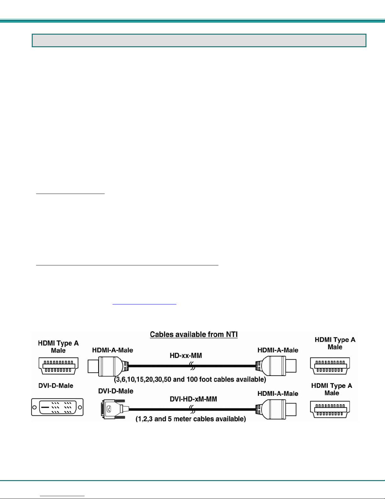
Material Not Supplied, but may need to be ordered
CAT5/5e/6 unshielded twisted-pair cable(s) terminated with RJ45 connectors wired straight thru- pin 1 to pin 1, etc. for Ethernet
connection
Cables can be purchased from Network Technologies Inc by calling 800-RGB-TECH (800-742-8324) or 330-562-7070
or by visiting our website at www.networktechinc.com
.
1
Page 6
NTI RACKMUX-D17HR-N-SUSBHD4 RACKMOUNT DRAWER WITH QUAD SCREEN MULTIVIEWER
RACKMUX SINGLE-PERSON INSTALLATION
Your NTI RACKMUX Drawer was designed for easy installation by one person with a minimum of tools and effort. Follow the
simple steps below to quickly install your RACKMUX Drawer.
If you would like to see a video of this installation, see the “single-person-installation
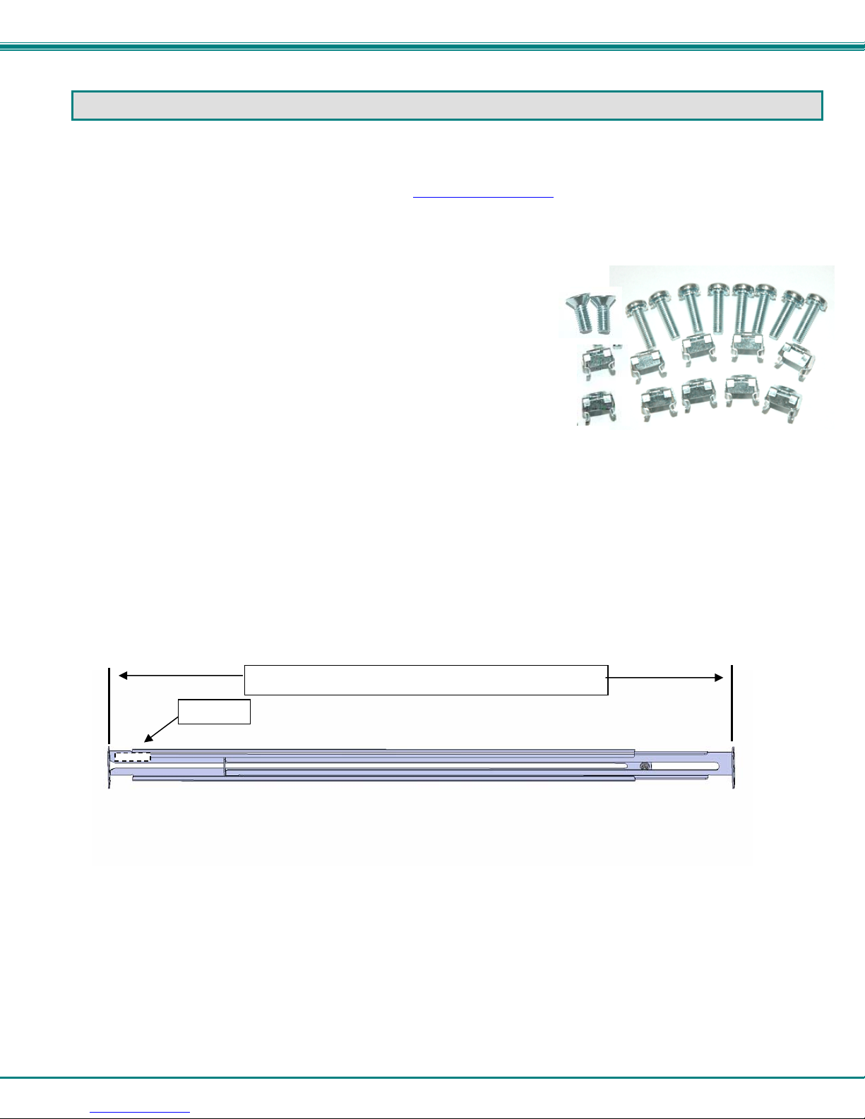
1. Locate and unpack the hardware bag. Your hardware bag will include all items n e cessary to install the specific RACKMUX
model (see the manual that accompanied your RACKMUX drawer), including the following hardware unique to the Single-Person
hardware installation:
10- #10-32 cage nut
2- #10-32 x 1/2” flat-head ma chine screw
8- #10-32 x 3/4” pan-h ead machine screw
T
install the rails you will need only a tape measure and Phillips screwdriver.
o
2. Unpack the left and right rail assemblies. Each are labeled “Right Front” and “Left Front” to indicate their intended position and
orientation. Extend each rail assembly to the dimension required for your rack. Rail assemblies are adjustable to fit within a rack
between 24” and 40” in depth.
Labeled
Rail assemblies are adjustable in length from 24” to 40”.
” video .
Figure 1- Adjustable rail assemblies
2
Page 7
NTI RACKMUX-D17HR-N-SUSBHD4 RACKMOUNT DRAWER WITH QUAD SCREEN MULTIVIEWER
R
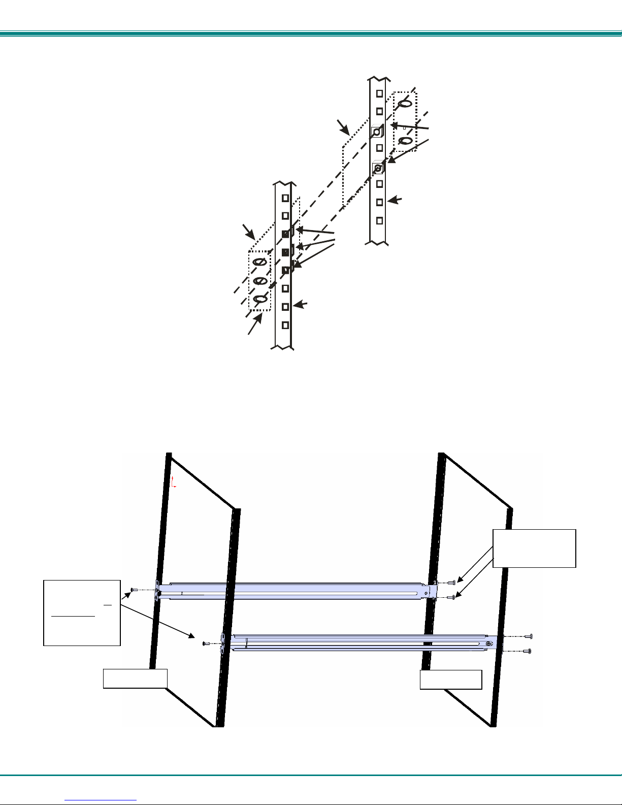
3. Install six #10-32 cage nuts at the front of the rack in positions where the RACKMUX will be mounted (three in each side).
Install four more cage nuts at the rear of the rack in positions straight across from the upper and lower cage nuts installed in front.
Ext ender Rail
Rail Flange
Extender Rail
Cage
Nuts
Rear Rack
Support
Cage
Nuts
Front Rack
Support
Figure 2- Install the cage nuts
4. Install the right rail assembly. The end with the label “Right Front” mounts to the front rack support. Install only the center
screw through the rail flange to the rack support and cage nut using the #10-32 x 1/2” flat head machine screw provided. (See
image below.) Do not tighten at this time. Install the left rail assembly in the same fashion. The end with the label “Left Front”
mounts to the front rack support.
5. Install two #10-32 x 3/4” pan-head screws in the rear of each rail assembly as shown below. Do not tighten at the time.
Install one flat
head screw in
the center in
each side at
the front
Rack Front
ack Rear
Install two
screws in each
Figure 3- Install the rail assemblies
3
Page 8
NTI RACKMUX-D17HR-N-SUSBHD4 RACKMOUNT DRAWER WITH QUAD SCREEN MULTIVIEWER
u
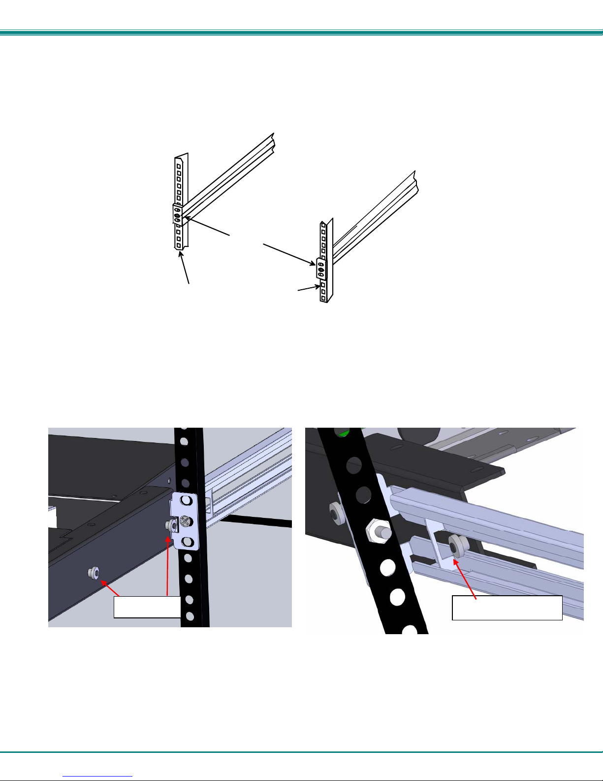
6. Measure the distance between the inside of the rails at the front of the rack. Adjust the distance to 17-1/4” and tighten the flathead screws to the rail flanges securely.
Left Rail
Right Rail
17-1/4"
Front Rack Supports
Figure 4- Check spacing of the rails
7. Lineup the rail guides on the RACKMUX drawer with the slots in the front of the left and right rails and slide the drawer into the
rack. The rail guides should be positioned such that the wide lip of the guide is on the backside of the rail. Slide the drawer in
completely.
View of rail guide from the
Rail guides
front of the rack support View of rail guide from the backside of the rail
Wide lip of rail g
ide
Figure 5- Rail guides
4
Page 9

NTI RACKMUX-D17HR-N-SUSBHD4 RACKMOUNT DRAWER WITH QUAD SCREEN MULTIVIEWER
8. Apply four more #10-32 x 3/4" pan-head machine screws (two for each) through the holes in the drawer flanges, through the
holes in the left and right rails, into the cage nuts in the rack supports. Tighten each securely.
Apply two
more screws
on each side
There should
be a total of
six screws
the front now.
at
Figure 6- Apply remaining screws to complete installation
9. Tighten securely the four screws applied to the rear rail flanges in step 4.
10. Make your cable connections according to your RACKMUX Drawer instructions.
Your NTI RACKMUX Drawer is now installed and ready for cable connections.
5
Page 10

NTI RACKMUX-D17HR-N-SUSBHD4 RACKMOUNT DRAWER WITH QUAD SCREEN MULTIVIEWER
CABLE CONNECTIONS
Connect Video Sources
1. Connect each of the HDMI or DVI video sources to the ports on the multiviewer (SPLITMUX) marked “HDMI Inx” (x = 1-4).
2. Connect the power cord to the AC input and plug it in.
3. Press the switch to power the RACKMUX ON. In approximately 40 seconds the SPLITMUX will boot up and be ready to use.
4. The RACKMUX keyboard provides keyboard control of the OSD menu of the SPLITMUX. The RACKMUX supports transparent
USB device connection such that the keyboard and touchpad mouse will also control the keyboard and mouse functions on any
connected PC.
5. For each video source that is a PC, connect a USB2-AB-0-5M-5T cable (sold separately) between a USB type A female user
device port on a CPU and a USB Type B female port on the SPLITMUX.
Figure 7- Connect each CPU and video source
6. Power-ON the video sources and CPUs.
The CPUs can be po wered at any time although if a CPU needs a keyboard and/or mouse at power-ON it should be
powered after connecting to and powering-ON the RACKMUX.
Note: The order in which the CPUs and switch are powered up does not matter. A power strip can be used.
7. Power-ON the RACKMUX. (The RACKMUX can be powered at any time.)
6
Page 11

NTI RACKMUX-D17HR-N-SUSBHD4 RACKMOUNT DRAWER WITH QUAD SCREEN MULTIVIEWER
Terminal Connection for RS232
If control via serial connection is going to be used, serial control can be achieved by connecting a control terminal to the “RS232”
port .
To use the “RS232” port, connect one end of a CAT5 patch cable (supplied) to the port labeled “RS232” on the rear of the
SPLITMUX. Plug the other end of the CAT5 cable into an RJ45-to-DB9F adapter (supplied), and connect the adapter to the
RS232 port on the control terminal.
Figure 8- Ethernet and RS232 Terminal Connection
Ethernet Connection for Remote User Control
To make a remote connection, over the Ethernet, from anywhere on the local area network, connect a CAT5/5e/6 Ethernet
cable with RJ45 male connectors on the ends, wired straight through (pin 1 to pin 1, pin 2 to pin 2, etc.). Up to 8 users can
connect to the SPLITMUX using the Ethernet at a time.
Note: Alternatively, a direct connection from a computer’s Ethernet port to the SPLITMUX “ETHERNET” port may also
be made using the same cable.
Connect Extra Device
On the front of the RACKMUX is an additional USB Type A port to be used, if desired, for an extra accessory. Any low or full
speed USB device may be connected to this port to be used. This port is fully compliant with USB standard 1.1.
Note: In order for the optional USB device port to be usable, the USB port on the rear of the RACKMUX must be
connected to a USB enabled CPU (a 2 meter USB cable is supplied).
Note: If a USB keyboard or mouse is connected, operation of the RACKMUX keyboard or mouse may cause
unpredictable results. Do not try to use both mice or both keyboards at the same time.
Connect optional USB 1.1 or 2.0 device
PRINTER
CAMERA
FRONT VIEW OF RACKMUX-V17
SCANNER
FLASH DRIVE
Note: If a USB 2.0 device is
connected to the optional
USB device port, it will
operate at USB 1.1 speed.
Figure 9- Connect a USB 1.1 device to the front (optional)
7
Page 12

NTI RACKMUX-D17HR-N-SUSBHD4 RACKMOUNT DRAWER WITH QUAD SCREEN MULTIVIEWER
FEATURES AND FUNCTIONS
#
LABEL PHYSICAL DESCRIPTION
1 Power
--- Green/Red LED Indicates operation status
2
Menu
3
Up Arrow
4
Down Arrow
5
Select
6
NumLock
7
CapsLock
8
Scroll Lock
9
10 USB (Symbol)
--- 3-button mouse for controlling mouse movements on the monitor and controlling the computer
11
--- Keylock to prevent unauthorized use of the RACKMUX
12
--- Auto Shut-OFF switch automatically shuts OFF the LCD display when the monitor is folded down
13
--- Keyboard for manual data entry and computer control
14
--- USB Type A for connection of USB 2.0 device (flash drive, printer, CAC reader, etc)
15
--- LCD Display for viewing the video signal from the connected CPU
16
--- IEC Connector for attachment of the IEC power cord to power the RACKMUX drawer
17
--- Main Switch for powering ON and OFF the RACKMUX drawer
18
19 HDMI Inx
20 CPU INx
21 RS232
ETHERNET
22
Button press to turn only the LCD monitor ON and OFF
Green = Power-ON, Video Input Signal OK
Red = Suspend / Stand-by, or no Video Input Signal
Button press to turn ON the OSD menu
Button press to move the cursor in the OSD menu up
Button press to move the cursor in the OSD menu down
Button press to select a menu item (when OSD menu is ON) or press to auto adjust the
video quality (when OSD menu is OFF)
Green LED illuminates when the number lock is ON
Green LED illuminates when CapsLock is ON
Green LED illuminates when the Scroll Lock keyboard feature is ON.
Green LED illuminates to indicate drawer is in USB Mode (should be ON at all times)
HDMI female for connecting video sources
USB Type B female for connection of video cables from video sources supplying Hi-Definition video- to
provide control over the sources
RJ45 female for attaching RS232 interface cable from a CPU to control the functions of one or
more switches
RJ45 female for connection to an Ethernet for remote user control
8
Page 13

NTI RACKMUX-D17HR-N-SUSBHD4 RACKMOUNT DRAWER WITH QUAD SCREEN MULTIVIEWER
CONTROL METHODS
The SPLITMUX, when built into a RACKMUX, can be controlled using any of four methods;
Command Mode using the local keyboard, and touchpad mouse
Using the Command Line Interface either through RS232 or remote connection
Using a Text Menu either through RS232 or remote connection
Remotely through the Web Interface using an Ethernet connection.
Command Mode
The attached keyboard and mouse will, by default, control the PC supplying the active video. The keyboard and mouse can also
be used for controlling Standard Mode functions as well as OSD Mode (see OSD menus on page 57 of the SPLITMUX-USBHD4RT Quad Screen Video Splitter manual.).
To control the SPLITMUX using the keyboard, press <Ctrl> + <`> (accent/tilde key) on the keyboard (press at the same time) to
enter Command Mode. While in Command Mode, all 3 status lights on the keyboard will illuminate to indicate that Command
Mode is enabled.
W
hen enter
Keypress Function
O (Letter “O”) Toggle OSD Menu (Open/ Close)
OSD Menu Navigation:
Down Arrow or Tab Move do wn thru OSD menu selections
Left/Right Arrow Change values of menu item
Press <Esc> to exit Command Mode.
ing Command Mode, the Standard Mode functions will be controlled as follows:
1 thru 4 Select Channels 1 thru 4
F switch to Full screen mode
Q switch to Quad mode
P switch to PIP mode
C switch to Custom mode
Enter Select the Menu item
L / R / U / D Move the OSD screen on the display
9
Page 14

NTI RACKMUX-D17HR-N-SUSBHD4 RACKMOUNT DRAWER WITH QUAD SCREEN MULTIVIEWER
To control the SPLITMUX using the touchpad mouse, move your finger on the pad from side-to-side rapidly. This motion will
place the SPLITMUX in Command Mode. While in Command Mode, all 3 status lights on the keyboard will illuminate to indicate
that Command Mode is enabled. The keyboard functions described on page 14 will be active while in Command Mode.
Figure 10- Shake mouse to enter Command Mode
While in Command Mode, Right-click the mouse to open the OSD menu. To exit the OSD menu, Right-click the mouse once
more.
To exit Command Mode after closing the OSD menu, either Left-click the mouse or press <Esc> on the keyboard.
For more on using the touchpad (mouse) to control the OSD menu, see page 57 of the SPLITMUX-USBHD-4RT Quad Screen
Video Splitter manual.
Figure 11- OSD Menu for the SPLITMUX
10
Page 15

NTI RACKMUX-D17HR-N-SUSBHD4 RACKMOUNT DRAWER WITH QUAD SCREEN MULTIVIEWER
In F
LL screen mode, only the active video source will be displayed. The image will be viewed at full size
U
and maximum resolution.
In QUAD screen mode, all four video sources share the
screen
equally. Each video source is displayed completely.
In PIP mode (right) , either 2, 3 or all 4 vide
displa
yed, with the active source being displayed in its
entirety on the full screen and the remaining selected
images at a reduced resolution for simultaneous viewing.
The position of the reduced images can be configured for
preferred viewing.
o sources can be
11
Page 16

NTI RACKMUX-D17HR-N-SUSBHD4 RACKMOUNT DRAWER WITH QUAD SCREEN MULTIVIEWER
In CUSTOM mode (below) the 4 video sources can be
placed where ever you want, at what ever size you want.
The amount of each source that is viewed is determined by
your configuration.
Much more i
multiviewer.html#tab-6 in man225.pdf entitled “SPLITMUX-USBHD-4RT Quad Screen Video Splitter Installation and Operation
Manual”
n
formation on the use of the SPLITMUX features can be found at
http://www.networktechinc.com/hdmi-
12
Page 17

NTI RACKMUX-D17HR-N-SUSBHD4 RACKMOUNT DRAWER WITH QUAD SCREEN MULTIVIEWER
DISPLAY FUNCTIONS
An NTI RACKMUX with a 17” monitor supports resolutions up to 1920 x 1200 with a refresh rate at between 55 and 76Hz. The
quality of the image on the LCD monitor is adjustable using an On Screen Display (OSD) menu using the control buttons on the
RACKMUX.
Standard Controls
The RACKMUX has 5 standard control buttons and a power LED. The 5 standard control buttons o perate as follows:
The Power button turns the RACKMUX LCD Monitor and backlight ON and OFF as desired.
The Power LED located immediately to the left of the Power button is a dual color LED. It will illuminate with a green color
when the RACKMUX is powered ON and has video sync. It will illuminate with a red color if the RACKMUX is powered ON
but there is no input signal detected.
The Menu/Select button is used to bring up the OSD menu where the various settings of the LCD display can be adjusted.
Once the OSD screen is displayed, the Menu/Select button is used to make selections within the menus. See "OSD
Control Menu" (below) for more on LCD display settings.
The Up and Down Arrow buttons are used to navigate through the menus. Move the cursor up or down as desired to
highlight an item for selection. Once an item is highlighted, pressing the Menu button will select it.
The Exit/Auto Adjust button will exit the OSD menu when visible. When the OSD menu is OFF, the button will act as an
Auto Adjust button to keep the user from having to use the menus to adjust the quality of the image on the monitor.
OSD Control Menu- 17 Inch Hi-Resolution Model (-HR)
The OSD (On Screen Display) Menu enables the user to select the desired characteristics of the LCD display. To activate the
OSD Menu, press the Menu button (below). To turn the Menu back OFF, either press the Exit button or just wait
approximately 10 seconds (timing is adjustable) and it will automatically be cleared from the screen. Any changes made before
exiting the menu will be saved.
Figure 12- OSD Controls
13
Page 18

NTI RACKMUX-D17HR-N-SUSBHD4 RACKMOUNT DRAWER WITH QUAD SCREEN MULTIVIEWER
OSD Main Menu
The Main Menu is broken into five sections, Color, Picture, Function, OSD Menu, and Misc. Press one of the arrow buttons to
move between them. The Picture and Function sections only apply when the RACKMUX is connected as VGA instead of DVI.
To select a menu and move to characteristics within them (i.e. CSM, Brightness, or Contrast under the Picture menu), press the
Select button while the desired menu is displayed.
Char
acteristics
Selection Purpose Range
Colour
Contrast
Brightness
Colour Temp.
Colour Adjust
Picture (VGA Only)
H Position
V Position
Phase
Clock
Sharpness
Function (Fx)
(VGA Only)
OSD Menu
Language
OSD H. Pos.
OSD V. Pos.
OSD Timer
Translucent
Misc.
Press the Exit button or select “Exit” to exit the OSD menu.
that can be adjusted are described in the chart below.
Increase/decrease panel contrast level
Increase/decrease panel brightness level
Set panel color temperature
Select RGB balance (goes to submenu)
Control Horizontal position of screen
Control Vertical position of screen
To manually force auto adjust of monitor settings Select Auto Adjust or Auto Color functions
Select the language of the OSD menu
Control Horizontal OSD Image position on screen
Control Vertical OSD Image position on screen
Control if OSD will time out
Adjusts how boldly the menu is displayed
Select Input
Reset monitor to default settings
0-100
0-100
5800K,9300K,6500K,User
0-100
0-100
0-100
0-100
0-100
1-5
English, Spanish, German, Italian, or French
0-100
0-100
On/Off If On, select 3-100 seconds.
-/+
VGA or DVI
Yes/No
14
Page 19

NTI RACKMUX-D17HR-N-SUSBHD4 RACKMOUNT DRAWER WITH QUAD SCREEN MULTIVIEWER
Colour Adjust submenu
Input submenu
15
Page 20

NTI RACKMUX-D17HR-N-SUSBHD4 RACKMOUNT DRAWER WITH QUAD SCREEN MULTIVIEWER
KEYBOARD FUNCTIONS
Numeric Keypad
This RACKMUX has a standard Windows keyboard with 17-key numeric keypad.
Figure 13- U.S. (English) keyboard with numeric keypad
Figure 14- Keyboard LED Indications
Note: If the PS/2 LED illuminates, the keyboard and mouse will quit functioning properly. To switch the RACKMUX back to USB
Keyboard/Mouse mode, press <Ctrl> + <T> keys at the same time for 8 seconds. The PS/2 LED will go OFF and the USB LED
will illuminate.
16
Page 21

NTI RACKMUX-D17HR-N-SUSBHD4 RACKMOUNT DRAWER WITH QUAD SCREEN MULTIVIEWER
SAFETY
This NTI product has been designed and fully tested with user safety of the utmost importance. As with all electronic devices, this
NTI product should be handled and operated with care. In order to avoid possible injury and to reduce any risk of damage to this
product, please read and follow each of these safety instructions.
Follow all instructions found in this manual
Follow all instructions found on the product
Do not attempt to perform any service on this product unless specifically instructed to in this manual
Do not remove covers or disassemble
Objects that can damage or be spilled on this product should be kept away from this product. Liquids, if spilled, could come
into contact with voltage points causing a risk of fire or electrical shock.
Always unplug this product before cleaning it
Do not use any liquid or aerosol cleaners to clean this product
Do not install or use this product near water
Be sure to mount this product on a solid, stable surface or in a rack (if applicable)
Route all cables and the power cord away from sharp edges or objects that could cause damage to them
Use only the power cord or AC adapter that came with this unit or one that meets the requirements specified in this manual
Use only a properly grounded 3-wire electrical outlet for power connection
Unplug this product and contact NTI should any of the following conditions occur:
The power cord or connection cables have been damaged
The product has come into contact with any liquids
The product does not operate properly despite having followed all of the ins t ructions
The product has been dropped or the case has been damaged in any way
The product performs distinctly different than it did when first put into service
17
Page 22

NTI RACKMUX-D17HR-N-SUSBHD4 RACKMOUNT DRAWER WITH QUAD SCREEN MULTIVIEWER
RACKMUX-KVM DRAWER STANDARD SPECIFICATIONS
General Specs
Case Material.................................................Electro-galvanized steel black powder coated
Dimensions WxDxH (in.)...............................19 x 23.9 x 1.75
Supported Rack Depths………………………..Adjustable 24” – 40”
Weight……………………………………………26 lbs.
Input Power....................................................AC 100-240V, 50 – 60 Hz
Operating Temperature..................................0-40˚C
Storage Temperature…………………………..-20-60˚C
Relative Humidity……………………………….. 20-90%, non-condensing
Approvals.......................................................All parts comply with RoHS
LCD – 17” Hi-Resolution
Display area…………………………………….379.3mm (W) x 244.6 (H) (17.1 inch diagonal)
Panel Type………………………………………TFT Active
Number of Pixels ...........................................1920 (H) x 1200 (V)
Color Depth....................................................6 bit,262,144 colors
Pixel Pitch......................................................0.191(H) x 0.191(V)
Brightness......................................................275cd/m2
Operating Lamp Life ......................................10,000 hrs
Display Controller: DVI
Connector………………………………………DVI-D, female
Video Format.................................................VGA,SVGA, XGA, SXGA
Signal Input (from Video Source)…………….Digital TMDS
Sync Range...................................................H: 31 ~ 80KHz, V: 55 ~ 76Hz
OSD Control…………………………………….Menu, Up, Down, Select, Power (5 keys)
Plug and Play.................................................VESA DDC 2B Ver1.3
OSD Control Board
OSD Control ..................................................5 Keys
Power Key .....................................................Power ON/OFF
Menu Key.......................................................Activates Menu
Up, Down Keys..............................................Navigation Control
Select Key......................................................Select (when in Menu); Auto Adjust (not in menu)
LED................................................................Indicates Operation Status
...............................................................Green = Power-ON, Video Input OK
...............................................................Red = Suspend / Stand-by, or Input Out of Range
Keyboard
No. Of Keys ...................................................104 Keys (US)
Key Switch Type............................................Membrane switch
Keytop Style...................................................Rectangular Cylindrical
Operating Force.............................................50gf +/- 25gf
Stroke ............................................................3.0mm +/- .5mm
Tactile............................................................20 gf typ.
Height ............................................................8.5 mm
Operating Life................................................10M operations, minimum
Interface ........................................................Row and column matrix
Key Switch Bounce........................................10 ms, maximum
Supported Platforms......................................USB, PS/2
CPU Connectors............................................USB Type B (USB);
18
Page 23

NTI RACKMUX-D17HR-N-SUSBHD4 RACKMOUNT DRAWER WITH QUAD SCREEN MULTIVIEWER
Touchpad
Motion Detection Method...............................capacitance sensing
X/Y Position Sensing Resolution ...................40 counts/mm
X/Y Position Reporting...................................Relative (Similar to mouse)
Tracking Speed..............................................Up to 1016 mm/sec
Touch Force...................................................No Contact pressure required
Lifetime (Plastic Overlay)............................... Minimum 10,000,000 strokes
Sample Rate..................................................Up to 100 samples/sec
19
Page 24

NTI RACKMUX-D17HR-N-SUSBHD4 RACKMOUNT DRAWER WITH QUAD SCREEN MULTIVIEWER
TROUBLESHOOTING FOR KVM DRAWER
Each and every piece of every product produced by Network Technologies Inc is 100% tested to exacting specifications. W e
make every effort to insure trouble-free installation and operation of our products. If problems are experienced w hile installing this
product, please look over the troubleshooting chart below to see if perhaps we can answer any questions that arise If the answ er
is not found in the chart, a solution may be found in the knowledgebase on our website at
http://information.networktechinc.com/jive/kbindex.jspa or please call us directly at (800) 742-8324 (800-RGB-TECH) or (330)
562-7070 and we will be happy to assist in any way we can.
Problem/Message Cause Solution
"OUT OF FREQUENCY"
"POWER SAVER MODE"
"NO SIGNAL"
"AUTO CONFIGURATION"
Keyboard/touchpad not
functioning
LCD is not displaying image
Input signal is outside the supported
range
The input signal is not present. This
message will disappear after 5 seconds.
The input signal is not present
immediately after power ON.
The LCD monitor is configuring itself for
proper communication with the CPU.
Keyboard is in the incorrect mode
Cables are not properly connected
Image out of range
LCD Auto-Shut OFF button is
depressed
LCD is powered OFF
Lower or raise video frequency to be within specified
range
Check all cable connections- verify that they are
secure and that video is available
Check all cable connections- verify that they are
secure
No action necessary
Toggle the keyboard mode from PS/2 to USB.
(Press <Ctrl> + <T> keys for 8 seconds)
Check all cable connections between the
RACKMUX and the computer.
Lower the resolution
Make sure nothing is resting on the button
Turn power to LCD ON
INDEX
accessory USB port, 7
Command Mode, 9
Display functions, 13
Drawer installation, 2
Ethernet, 7
features, 8
numeric keypad, 16
OSD Controls, 13
terminal, 7
USB port, 7
WARRANTY INFORMATION
The warranty period on this product (parts and labor) is two (2) years from the date of purchase. Please contact Network
Technologies Inc at (800) 742-8324 (800-RGB-TECH) or (330) 562-7070 or visit our website at http://www.networktechinc.com
for informatio
MAN264 Rev.8/10/18
regarding repairs and/or returns. A return authorization number is required for all repairs/returns.
n
20
 Loading...